Attach Policies to Interfaces
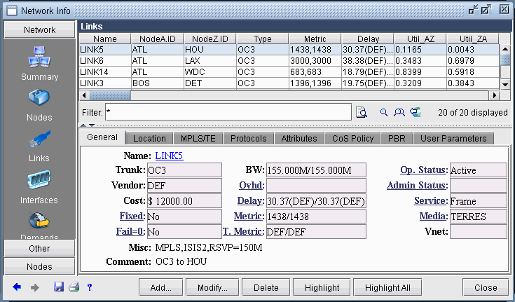
The last step is to attach policies to interfaces. A link between routers is composed of two interfaces so two policies can be attached per link. Click on the Modify > Elements > Links item menu to bring up the link listing.
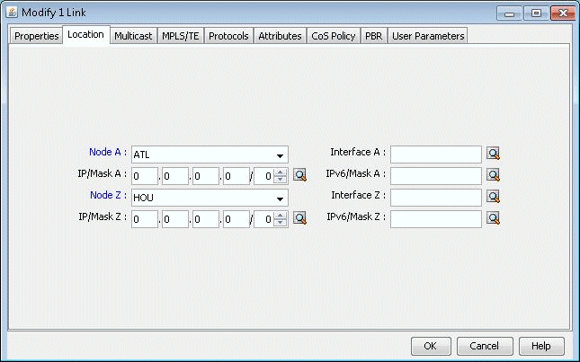
Click on the Modify button and select the Location tab to enter the IP addresses and interface names of the two end-points, if available.
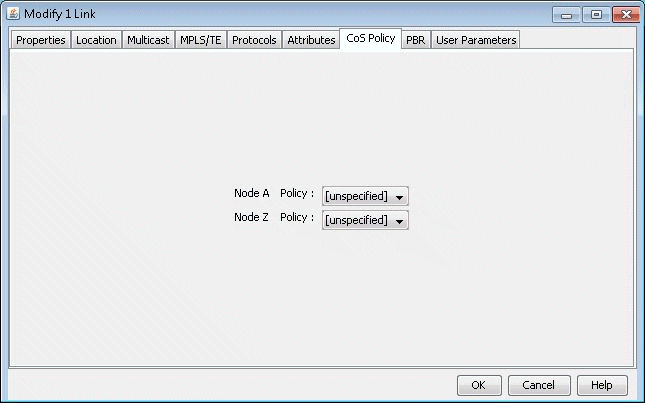
Finally, click on the CoS Policy tab to attach policies to interfaces. In <Link>Figure 207 below, you can specify policies on the Node A and Node Z endpoints of a link. Note that only the CoS Policies that are applicable to the Node A router will be listed under the Node A Policy drop-down menu, and likewise for Node Z. Recall that in Create Policies for Classes , the user can specify a particular router or “[Any Router]” for each newly created policy.
Related Cisco commands:
At the interface level (config-if) the command to attach a policy to an interface is:
Router(config-if) # service-policy {input| output} policy-mapwhere input is to indicate the input interface, output for output interface, and policy-map is the name of the policy-map defined somewhere else in the config file.
Example:
Router(config) # interface e1/1
Router(config-if) # service-policy output policy1