ON THIS PAGE
Subscribers and System Settings
You can access Subscribers and System Settings by selecting Administration from the More Options menu in the upper right corner of the NorthStar Controller UI. These options are visible to and accessible by the Admin user only.
Subscribers
The Admin can assign users to receive system messages by navigating to Administration > Subscribers. Click Add in the upper right corner of the Subscriber Management window to display the Add Subscriber window as shown in Figure 1.
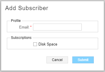
Enter the email address of the user to be subscribed (under Profile) and select the type of system messages to be received (under Subscriptions). Only disk space notifications are available at this time. Click Submit to complete the subscription. See General System Settings for information about customizing disk space notifications.
Once subscribed, the user receives system messages and can then take the appropriate action.
In addition to adding subscribers, the Admin must also navigate to Administration >System Settings and ensure that the SMTP Mail Server is enabled in the Outgoing Mail section. If the mail server is disabled, subscribers cannot receive system messages.
You can modify or delete existing subscribers by clicking Modify or Delete in the upper right corner of the Subscriber Management window.
System Settings
Navigate to Administration > System Settings from the More Options menu to access the general system settings shown in Figure 2:
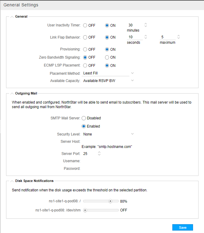
In the upper right corner of the General Settings window is an Advanced Settings button. This button allows you to toggle back and forth between general and advanced system settings. The advanced system settings are shown in Figure 3.
General System Settings
The general settings are described in Table 1.
|
Setting |
Description |
|---|---|
|
User Inactivity Timer |
When enabled, users are automatically logged out of the NorthStar Controller after the specified period of inactivity. The timer is disabled by default. To enable it, select On and enter the time in minutes. |
|
Link Flap Behavior |
Link flap can be enabled or disabled, and is disabled by default. There are two parameters involved:
|
|
Provisioning |
Provisioning can be globally enabled or disabled for all users, and is enabled by default. Disabling provisioning does not prevent users from accessing and using the provisioning functions in the UI, but it does prevent those actions from taking effect in the network. This allows you to respond to periods of network instability by preventing the additional strain on the system that might result from provisioning going on at the same time. |
|
Zero Bandwidth Signaling |
When set to On, NorthStar can optimize resource utilization more effectively and more aggressively. When set to Off (the default), some LSPs might not be routed due to bandwidth overbooking when a make-before-break (MBB) operation is performed. |
|
ECMP LSP Placement |
Off: NorthStar chooses the first shortest path it calculates when performing path computation. On: After considering link metrics, if there are multiple shortest paths available, NorthStar further considers link RSVP bandwidth utilization when performing path computation. This takes effect whenever path computation is required, such as when LSPs are provisioned, when a link goes down requiring LSP rerouting, when path optimization is initiated, and at the beginning and end of maintenance events. When you enable ECMP LSP Placement, you must select the placement method as either:
Limitation as of Release 5.1.0: When provisioning LSPs via NETCONF, the PCS does not allocate bandwidth until it receives a response from either the configServer or PCEP. This is a different behavior from provisioning LSPs via PCEP where the PCS allocates bandwidth immediately. When provisioning LSPs via NETCONF one at a time, there is the potential for a provisioning order to be sent before the response to a previous provisioning order is received—which means the second order might not have correct bandwidth allocation information and NorthStar might not be able to provide ECMP. We recommend provisioning multiple LSPs via NETCONF in one operation (bulk provisioning) in order to avoid this issue. |
|
SMTP Mail Server |
The SMTP mail server must be enabled for subscribers to receive system messages. |
|
Disk Space Notification Thresholds |
For each partition, you can set the disk usage threshold that triggers a system message to be sent out to subscribers as configured in Administration > Subscribers. Click on the slider and drag to adjust the threshold. |
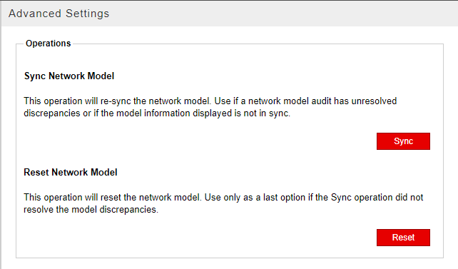
Advanced System Settings
In the Advanced System Settings window, there are two operations available to the administrator that help keep NorthStar’s view of the network (the network model) synchronized with the live network:
This is not the same thing as Sync with Live Network which is available by navigating to Administration > Device Profile. The Sync with Live Network button in the Device List window allows you to initialize device profiles with the live network. See Device Profile and Connectivity Testing for more information about that function.
-
Sync Network Model
The Sync Network Model operation refreshes the synchronization of the network model and is appropriate to use if, for example, the network model audit has unresolved discrepancies.
When you sync the network model, this is what happens behind the scenes:
-
Information associated with the network model (nodes, links, LSPs, interfaces, SRLGs, and user-defined parameters) remains intact. Nothing is purged from the database.
Note:Device profiles are not affected.
-
NorthStar processes, including the topology server and path computation server processes, are restarted.
-
The network model is repopulated with live data learned from topology acquisition.
-
-
Reset Network Model
Warning:This operation is typically more appropriate for a lab rather than a production environment. We highly recommend you use it only at the direction of JTAC.
The Reset Network Model operation should not be undertaken lightly, but there are two circumstances under which you must reset the network model in order to keep the model in sync with the actual network:
-
The node ISO network entity title (NET) address changes. This can happen when configuration changes are made to support IS-IS.
-
The routing device’s IP address (router ID) changes. The router ID is used by BGP and OSPF to identify the routing device from which a packet originated. The router ID is usually the IP address of the local routing device. If a router ID has not been configured, the IP address of the first interface to come online is used, usually the loopback interface. Otherwise, the first hardware interface with an IP address is used.
If either of these addresses changes, and you do not perform the Reset Network Model operation, the network model in the NorthStar Controller database becomes out of sync with the live network.
When you reset the network model, this is what happens behind the scenes:
-
Information associated with the network model (nodes, links, LSPs, interfaces, SRLGs, and user-defined parameters) is purged from the database (so you would not want to do this unless you have to).
Note:Device profiles are not affected.
-
NorthStar processes, including the topology server and path computation server processes, are restarted.
-
The network model is repopulated with live data learned from topology acquisition.
-
Table 2 describes the effects on various elements in the network when you reset or synchronize the model.
|
Is the element removed from the database? |
Is the item sent back to the controller by the live network? |
Could data be lost? |
||||
|---|---|---|---|---|---|---|
|
Reset |
Sync |
Reset |
Sync |
Reset |
Sync |
|
|
IP nodes |
Yes |
No |
Yes |
Yes |
Yes for some design attributes, such as user-defined node name |
No |
|
IP links |
Yes |
No |
Yes |
Yes |
Yes for design attributes such as Comment |
No |
|
PCC-controlled LSPs |
Yes |
No |
Yes |
Yes |
No |
No |
|
PCC-delegated LSPs |
Yes |
No |
Yes for PCEP attributes |
Yes |
Yes for non-PCEP attributes such as design flags |
No |
|
PCE-initiated LSPs |
Yes |
No |
Yes for PCEP attributes |
Yes |
Yes for non-PCEP attributes such as design flags |
No |
|
Multilayer nodes |
Yes |
No |
Yes |
No |
Yes for some designed attributes such as user-defined names |
No |
|
Multilayer links |
Yes |
No |
Yes |
No |
Yes for design attributes such as Comment |
No |
|
Interlayer links |
Yes |
No |
No |
Yes, links mapped to known nodes are re-sent. |
Yes |
Yes, access links to unknown nodes are lost and need to be recreated |
|
Multilayer-derived facilities |
Yes |
No |
Yes |
No |
No |
No |
|
Link-derived facilities |
Yes |
Yes |
Yes |
Yes |
Yes |
Yes |
|
Ongoing maintenance events |
No |
No |
N/A |
N/A |
No |
No |
|
Future maintenance events |
Yes |
No |
N/A |
N/A |
Yes |
No |
|
Ongoing scheduled LSPs |
No |
No |
N/A |
N/A |
Yes (scheduled LSP is never terminated) |
No |
|
Future scheduled LSPs |
Yes |
No |
N/A |
N/A |
Yes |
No |
|
Device profiles |
No |
No |
N/A |
N/A |
No |
No |
|
Router latitude and longitude |
No |
No |
N/A |
N/A |
No |
No |
|
Router grouping |
No |
No |
N/A |
N/A |
No |
No |
|
Users table |
No |
No |
N/A |
N/A |
No |
No |
|
Saved map layout |
No |
No |
N/A |
N/A |
No |
No |
|
Events |
No |
No |
N/A |
N/A |
No |
No |
|
Scheduled path optimization |
No |
No |
N/A |
N/A |
No |
No |
It’s worth stressing again that Reset Network Model is a drastic action that wipes out both the network data model and all the information you have manually provided through the Add/Modify functions in the network information table (user model data). We strongly recommend that you only perform this action if instructed to do so by JTAC.