ON THIS PAGE
Network Menu: Demands
From the main menu select Network > Elements > Demands to open the Demands window. “Demands” is a generic terminology used in NorthStar Planner. It is equivalent to “PVCs” in ATM networks or end to end “flows” in router networks.
Demands: Properties Tab
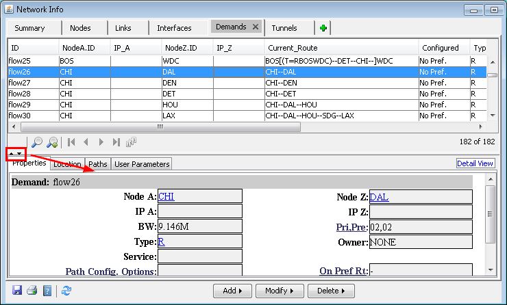
Figure 1 shows the Properties Tab under Demands. Table 1 describes the fields in the Properties tab.
Field |
Description |
|---|---|
Demand |
The demand name specified by you when the demand was added. |
Node A, Node Z IP A, IPZ IPv6 A, IPv6 Z |
Displays the source node (Node A) and termination node (Node Z) of the demand and their IP addresses (router model only). |
BW |
This is the bandwidth required by the demand. Demand overhead is automatically calculated by the program. |
pri,pre |
The priority and preempt fields of the demand specification consists of two numbers separated by a comma (,). The first number defines the priority of the demand, and the second number the preempt priority of the demand. The preempt priority should be at the same or lower priority as the priority of the demand. It is assumed that this demand can bump any of the demands with priority lower than the preempt priority. See Further Notes on Priority and Preemption. |
Type |
Indicates the type of the demand, whether it is a data demand or voice demand. |
Owner |
Displays the name of the owner of this demand. Owner groups can be defined using the Owners section in the Modify menu. |
Service |
Indicates the user-defined service type of the demand (for example, FTP, VOIP) as described in Network Menu: Service Type. |
Path Config Options |
For the optical transport model, this will indicate if the demand is a 1+1 demand |
On Pref Rt (On Preferred Route) |
Indicates whether or not the path is routed on the primary configured route. ‘yes’ means the path is routed on the primary configured route ‘no’ means the path is routed but not on the primary configured route ‘-’ means there is no configured route ‘not routed’ means the path failed to be placed |
Comment |
User-entered comments |
Demands: Paths Tab
Field |
Description |
|---|---|
Current Route |
This is the current route/path of the demand. This path is calculated by the program according to the metric, partitions, etc. as specified by you in the Design options.
|
Configured Paths |
This field displays the user-configured route/path for this demand. This route is specified by you in the Add/Modify Single Demand window.
|
Secondary |
Displays all secondary routes/paths of the demand. Secondary routes are also specified by you in the Add/Modify Single Demand window. |
Adding a Single Demand
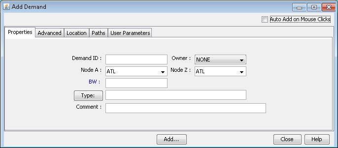
To add a single demand, click the Add > One demand button. Enter in the source (Node A), destination (Node Z), bandwidth (BW) and a demand identifier (Demand ID). For an explanation of the parameters in this window refer to the table below.
Properties
Field |
Description |
|---|---|
Demand ID |
The Demand identifier as specified by you. |
Owner/VPN |
Displays the name of the owner of this demand. Owner groups can be defined using the Owners section in the Modify menu. In router models, this shows the VPN in which the demand belongs. |
Node A |
Originating node of the demand. |
Node Z |
Destination node of the demand. |
BW |
The bandwidth required by the demand. Overhead is automatically calculated by the program. |
Type |
Indicates the type of the demand. (varies with different hardware types) |
comment |
Comments attached to the demand definition. You should note that comments are not used in any part of the modification, design, or simulation of the program and are merely provided as a convenience. |
Advanced
Field |
Description |
|---|---|
pri,pre |
The priority and preempt (or holding priority) fields of the demand specification consists of two numbers separated by a comma (,), or a forward-slash (/). The first number defines the call priority of the circuit, and the second number the preempt priority or holding priority of the circuit. The preempt priority or holding priority should be at the same or lower priority as the call priority of the circuit.
|
Service |
Indicates the service type of the demand. The available service types can be found in the Service Type window as detailed in Network Menu: Service Type. |
Path Config. Options |
Displays the path configuration options used to mark current routes as configured paths or to remove configured paths. Options available are: Config, Div. Sec. and Div. Stdby.
|
Location
An asterisk (*) denotes a hardware specific field.
Field |
Description |
|---|---|
Node A |
Displays the source node of the demand. |
IP A* |
Displays the IP address of node A. |
IPv6 A* |
Displays the IPv6 address of node A. |
Node Z |
Displays the destination node of the demand. |
IP B* |
Displays the IP address of node B. |
IPv6 B* |
Displays the IPv6 address of node B. |
Paths
Field |
Description |
|---|---|
Pathname |
This is the user-specified name of the route for this demand. This pathname is specified by you in the Add/Modify Single Demand window. |
Opt |
This field indicates the priority of this path/route in the “Opt” field. In the “Opt” field, the program will select the smallest number to be the primary route. For example, you may specify an Opt 2 for route “Backup1” and Opt 5 for “Backup2”. The program will sort these two routes and select Backup1 to be the primary route since its Opt is smaller. |
Configured Path |
This field displays the user-configured route/path for this demand. This route is specified by you in the Add/Modify Single Demand window.
|
Configuring the Demand Path
When adding a demand, you can configure a path or route for the demand.
This feature applies for connection-oriented networks like ATM where a path can be preferred or required. (For IP/MPLS networks, configuring the demand path applies only for tunnels, not for demands.)
To configure the path, underneath the “Demands / Paths associated with this demand” section, first double-click the Pathname field to change the pathname so that it is no longer “Dynamic”. There are multiple ways to configure the path through the graphical interface.
One way is to select Click links/nodes on map, then right-click in table next to where it says “To choose paths.” Then, <Ctrl>-click all the links along the path, right-click the relevant row entry in this table, and then select Use Map Sel’n.
Another way is to select Click consecutive nodes starting at node A next to where it says “To choose paths.” Then click the nodes from source to destination to automatically populate the Configured Route. Because this method is based on nodes only rather than including the links, this method cannot be used to select a particular link when there are parallel links between two nodes.
Finally, another method is to right-click an entry and select Edit Route to open a window where you are given options for each next hop until the destination is received.
Edit Route
Field |
Description |
|---|---|
Current Node |
Displays the current originating node from which the path of this demand is to be specified. |
Circuit ID / Flow ID |
Displays the name of the demand as specified by you. |
Next Available Hop(s) / Available Nodes |
Here, you can select three methods to choose the next hop or path for this demand. The Node ID/Name option allows you to select the next hop by choosing the next node of the path. The Link Name option allows you to select the path of the demand by choosing the links on which the demand will traverse. Lastly, with the Loose Route option, the program displays a list of routes calculated |
Add to Path |
Clicking on this button will add the highlighted hop or path to the path list. |
Delete from Path |
Deletes the highlighted path from the current path list. |
Show Path |
Selecting this button displays the path in the topology map. The path is displayed in a think yellow line. |
Clear Selections |
This will clear the list of chosen paths from the current paths section of this window. |
Hop Disp Opt |
Allows you to set the next available hop using the IP address or node ID/name. |
Defined Path |
As you defines and adds to the path for the demand, this field will progessively display the path as specified by you. |
User Parameters
User parameters allow you to define their own parameters for network elements such as nodes, links and demands, and then to associate values to these parameters for the individual network elements.
Demand Type Parameter Generation
Click the Type button in the Add or Modify Demands window to access additional demand settings. Clicking OK causes the Type field to be populated with the corresponding keywords. Note that different parameters will appear for different hardware device models.
Field |
Description |
File Format |
|---|---|---|
Max Delay |
Specify a maximum delay constraint (default in milliseconds). |
MAXDELAY=x (optional unit ‘s’ or ‘ms’ for seconds and milliseconds) |
Max Hop |
Specify a maximum hop constraint |
Hcnt |
Max Cost |
Specify a maximum end-to-end cost of the path ( for example, sum of the metrics/admin weights) |
MAXCOST=x |
Frame Size |
Used to calculate overhead. |
BFsize |
Diversity |
Specify the name of a group of demands this demand belongs to. When performing diverse path design, the program will try to design the paths of the demands in this group to be diverse. |
Ddivgroupname where divgroupname is the name of a group of paths |
Guaranteed BW |
Specifies that the demand should route over a Guaranteed Bandwidth (for example, subpool) tunnel |
GB, |
Full Duplex |
If this checkbox is selected, the flow is routed along the same route in both directions. |
DUPLEX, |
Policy Class |
CoS Policy |
COS=policyname, where policyname is substituted by the CoS policy name |
Multicast |
If this checkbox is selected, specify the destination IP in the adjacent select menu. |
MCip-address, where ip-address is substituted by the destination IP address |
PIM Mode |
The following Protocol Independent Multicast modes can be specified:
|
pim-mode, where pim-mode is substituted by the multicast mode (for example, PIM-DM) |
Admin Status |
These are labels for status classification that can be applied to a demand or tunnel.
|
LIVE is live MOD is modified NEW is new PLAN is planned SHUTDOWN is shutdown |
ECMP |
Specify that this demand can be load-balanced to Equal Cost Multiple Paths: specify a number in the adjacent textbox to specify the number of sub-flows that the flow can be broken down into |
ECMP= n, where n is substituted by an integer |
Adding Multiple Demands
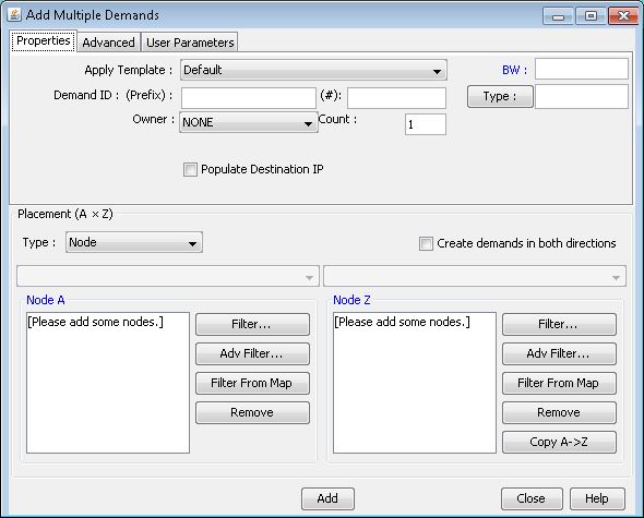
Select Add > Multiple Demands to add multiple demand definitions to the network at one time. A list box is used to indicate the origin (Node A) and destination (Node Z) locations. Meshed demands are created between all locations listed in Node A and Node Z.
Field |
Description |
|---|---|
Apply Template |
Specifies the circuit identifier assigned by you to the demand. |
Demand ID (Prefix and #) |
Specifies the demand suffix number assigned for multiple demands. This number will automatically increment. |
Owner |
Specify the name of the owner of this demand or the VPN in which this demand belongs. Owner groups can be defined using the Owners section in the Modify menu. VPN can be defined using the Add/Modify IP VPN window in the Modify menu. |
Count |
Specifies the number of demands to be added between node pairs. |
BW |
This is the bandwidth required by the demand. Demand overhead is automatically calculated by the program. |
Type |
Indicates the type of the demand, whether it is a data demand or voice demand. This field also indicates parameters for QoS networks. See Demand Type Parameter Generation. |
Pri,Pre |
The priority and preempt priority (or holding priority) fields of the demand specification consists of two numbers separated by a comma (,), or a forward-slash (/). The first number defines the call priority of the circuit, and the second number the preempt priority (or holding priority) of the circuit. The preempt priority should be at the same or lower priority as the call priority of the circuit. See Further Notes on Priority and Preemption |
Service |
Indicates the service type of the demand. The available service types can be found in the Service Type window. For more information on service types, see Network Menu: Service Type. |
Path Config. Options |
Specifies the path configuration option, which can be Config, Div.Stdby, or Div.Sec. |
Comment |
Displays any comments you may be inclined to enter. |
Populate Destination IP |
Specifies that the destination IP Address of each new demand should be automatically populated. |
Filter: Opens the Find Nodes window in order to add nodes to the Node A and Node Z lists.
Filter From Map: Adds nodes to the Node A and Node Z lists that are highlighted on the topology map.
Remove: Remove the selected node from the Node A or Node Z list.
Copy A-> Z: Copies the nodes that are on the Node A list to the Node Z list.
Adding One Hop
The Add > One Hop option allows you to create two demands per link, one in each direction. Because these demands have adjacent source and destination nodes, they are referred here as “one hop demands.” For example, for a link connecting ATL to DAL, the program can create two one-hop demands, one from ATL to DAL and one from DAL to ATL.
The purpose of this feature is to allow you to analyze the network to find out which demands are routed over the direct link and which are routed over a detour path. The detour path may be taken, for example, if the metric of the direct link is higher than that of the detour path. You can then check to see whether the detour path was intended or not.
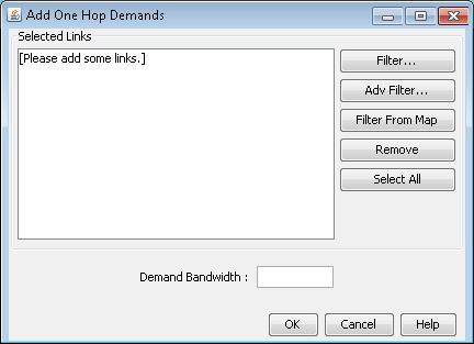
Upon opening the following window, you should perform a Filter... or Filter From Map to select the links for which to add one-hop demands. Then enter a bandwidth and bandwidth unit for the demands to be added, for example, 1M for 1Mbps, and click “OK”.
For information on the Add One Hop Tunnels feature, see the NorthStar Planner Feature Guide. Whereas for demands, the routing is left dynamic in order to allow discovery of multi-hop paths, for tunnels, an explicit tunnel path over the selected link is given to force the tunnel over the direct link. There are also additional options to label the added tunnels with a tunnel user parameter for the tunnel ID group.
Modifying a Single Demand
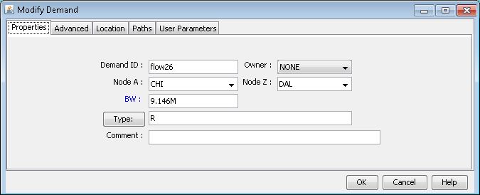
When you select Modify > Selected... for only one entry in the Network Info window Demands view pane, the following window is opened. You must first select a set of demands to modify in the table.
Paths Tab
Path Table: When selected, a table will appear displaying each configured or calculated path that originates at the source node of this demand. Note that these paths are not necessarily associated with the demand, and are not to be confused with the configured or current path taken by the demand.
Show Route: When selected, this button displays the highlighted path in the detailed demand information window.
Show All Paths: This option displays all paths listed in the detailed demand information window.
Modifying Multiple Demands
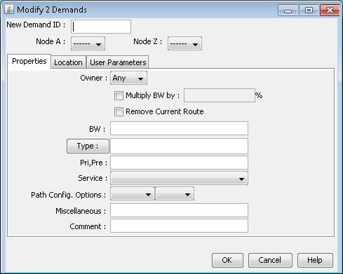
When you select Modify > Selected... for multiple entries in the Network Info window’s Demands view pane, the following window is displayed.
Field |
Description |
|---|---|
New Demand ID |
This option can be used to change multiple demands to have the same Demand ID. In most cases Demand IDs are unique and this option will not be needed. However, for certain features, the same demand ID may be used for different demands in order to group them together. These features include multicast demands (ATM or router hardware) and virtual concatenation groups (optical transport only). |
Multiply BW by |
When this checkbox is selected, the program will perform a bandwidth multiplication by the percentage specified here. The bandwidth of every demand selected for modification is multiplied by this percentage. |
Remove Current Route |
When this checkbox is selected, the program will remove the current route for the demands being modified. Accordingly, those demands are unplaced and the Current_Route column of the demand window is cleared for those demand entries.
|
Right-Click Menu Options
Show Path: Displays the path of the demand in the topology map, if it is routed. If multiple demands are selected, their paths are highlighted on the topology map, and the demand currently selected in the path window is highlighted with a slightly different color.
Highlight All: Displays on the Standard map the source to destination pairs of all demands listed in this window.
Bottlenecks: Displays the location of the bottleneck in the console when a demand is unplaced.
BW_Ovhd: Displays the bandwidth used by the demand and also the actual bandwidth allocated to the demand. This information is displayed in the console window.
All Configured Routes: This option displays on the map the configured routes for this demand. If the path is dynamic rather than configured, you should use the Show Path option instead.
Path Table: When selected, a table will appear displaying each configured or calculated path that originates at the source node of this demand. Note that these paths are not necessarily associated with the demand, and are not to be confused with the configured or current path taken by the demand.
End-to-End Delay: View a chart of the end-to-end delay per period as described in End-to-End Delay. Show Traffic Load: View a chart of the traffic load per period in the network as described in Traffic Load.
Show Site Demands: Display site-to-site demands on topology map, with a legend to indicate the load between each site pair. See Network Menu: Show Site Demands for more information.
Aggregate Demands: View the total bandwidth between each node pair in table format. See Network Menu: Aggregate Demands/Tunnels for more information.
Notes on Priority and Preemption
The Priority and Preempt Priority (or “pri,pre”) values of a demand (or MPLS LSP tunnel in Router models) influences routing order and placement. Note that although NorthStar Planner uses the term “preempt priority” throughout its graphical interface, for a majority of hardware types, if supported, this value actually maps to a demand’s Holding Priority. NorthStar Planner will mimic the behavior of the hardware device.
Note that Holding Priority and Preempt Priority differ subtly in meaning. A demand with a holding priority of some value x indicates that “any demand with a priority higher than x can preempt this demand.” A demand with a preempt priority of some value x indicates that “this demand can preempt any demand that has a lower priority.” Net.com Promina hardware, for example, uses “preempt priority”. The majority of supported ATM and router hardware, however, use a “holding priority” implementation (for the routers, this applies to MPLS LSP tunnels, as opposed to demands).
Also, for the majority of supported hardware models, a lower number indicates a higher priority. For a few hardware types, however, it is the reverse. Refer to your hardware’s documentation to check for the proper numbering scheme. NorthStar Planner will mimic the hardware’s behavior.
For example, suppose a demand has a pri,pre value of (7,0). Assume the lower value receives a higher priority. So, a “0” holding priority is already the highest priority and indicates that no demand is able to preempt this particular demand. The “7” priority value is used to determine routing order. If demands are placed with higher priority demands first (the default), then this demand will not be routed until after the demands of priorities 0 through 6 are routed.
The preempt priority, or holding priority, should always be set to a higher priority than the priority value. To illustrate, assume that we are dealing with holding priorities, as defined earlier, and that the lower value receives a higher priority. Then, a pri,pre value of (7,8) is invalid. To understand why, imagine if you had two such demands with pri,pre values of (7,8). One demand, of holding priority 8, could be preempted by the other demand, whose priority is 7. The preempting demand could then become preempted by the original demand, causing an oscillating scenario.
Demand Statistics View
The statistics view can be obtained by right-clicking a demand and selecting View > Statistics View. The tabs are explained below:
Field |
Description |
|---|---|
General |
The General demand information tab displays the total amount of placed and unplaced voice and data demands found in the network in terms of bandwidth. |
Pri Load |
The Priority Load tab sorts the demands found in the network by their defined priority and displays them in a table form in the demand information window. |
BW & Ovhd |
The BW & Ovhd tab provides summary information on the bandwidth and overhead of the demands shown in the Demands window. The program calculates the bandwidth of the demands including the overhead calculation and summarizes this data in this tab. Note: This tab is only activated when you are viewing demands on/thru a specific link. (Right-click on a link; select View > Demands On/Thru Link.) |
N Hop Path |
The NHop Path tab categorizes the demands found in a network by the total number of hops in each demand's route. |
Traffic Load
As a prerequisite, you should load in the trafficload file, which details the period by period bandwidth utilization.
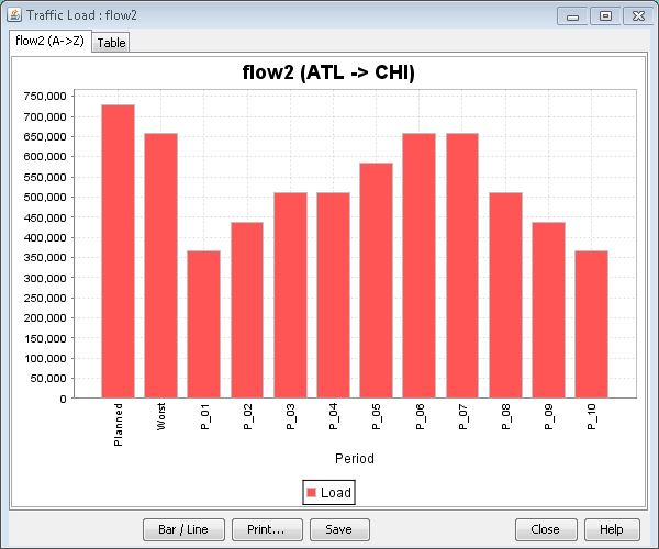
Right-click a demand from the Network Info window’s demand view pane and select Show Traffic Load to view the traffic load for a single demand or Show All Traffic Load to view the sum total traffic load for all demands. This displays the Traffic Load window, displaying the traffic load in either barchart or line form.
In the traffic load graph show below, the Y-axis displays the traffic load in megabits per second. One bar is displayed on the barchart for each of up to 24 time periods. The first two bars display the planned or normal bandwidth ("N") and the worst or peak traffic load ("W") which occurred during those periods.
End-to-End Delay
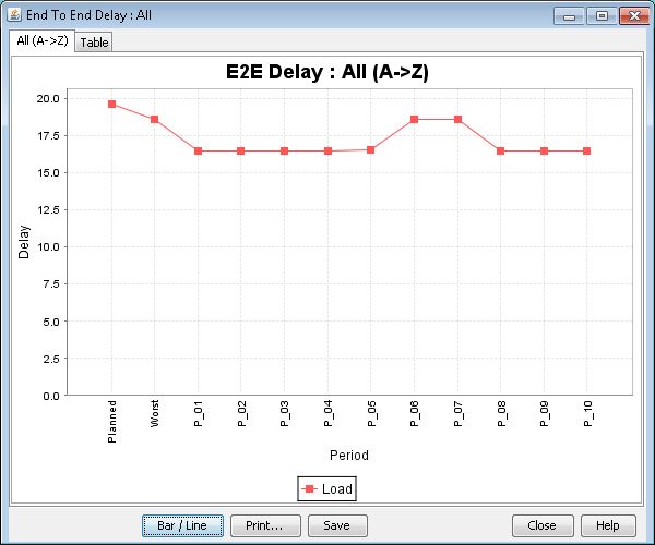
Right-click a demand from the Network Info window’s demand view pane and select End-to-End Delay to view the period to period end-to-end delay for a single demand or All End-to-End Delay to view the average of the end to end delays for all demands in the networks. This displays the Traffic Load window, displaying the traffic load in either bar chart or line form.
The End-to-End Delay graph displays the delay experienced by the demands in the network. In the graph, the end-to-end delay is shown in milliseconds. The delay found in the planned and peak bandwidths are shown as the first two bars in the graph.
Find Demands Filter
Click the Search by Property button in the Demands window to open the Find Demands window. The Find Demands window is a utility for filtering demands by matching the fields entered. Fields that are left blank are ignored.
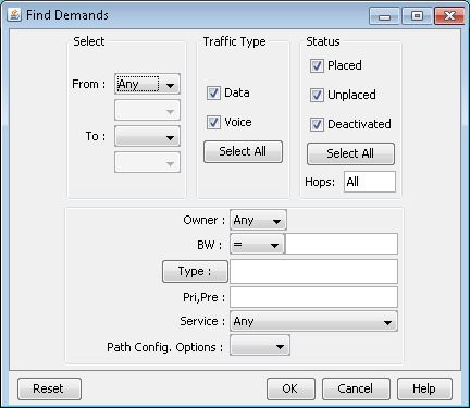
The From fields indicate the starting Node, Site, Lata, Group, or Area. For example, if you select Group this will find all the demands originating at a node in the selected topology group. Select Flow ID to indicate a specific demand.
The Status section can be used to narrow down on the demands of a particular status. For example, to view only the Unplaced demands, deselect the checkboxes for Placed and Deactivated.
The Type field is used to hold many specific demand type parameters, separated by commas. Pressing on the Type button will open the Demand Type Parameter Generation window, which can be used to help you automatically populate the Type field.
The Type field is used to hold many specific demand type parameters, separated by commas. Pressing on the Type button will open the Demand Type Parameter Generation window, which can be used to help you automatically populate the Type field.
After you have entered any demand properties in the Find Demands window, the program will match the properties entered and return a list of demands matching those properties. For example, if you want to search for all demands that have a bandwidth of 5 megabytes both way, you would enter an “5M” in the A->Z and Z->A fields. Then click on the OK button to retrieve the list of demands.
