ON THIS PAGE
NorthStar Egress Peer Engineering
Overview
Egress Peer Engineering (EPE) allows users to steer egress traffic to peers external to the local autonomous system, by way of egress ASBRs. NorthStar Controller uses BGP-LS and the SIDs to the external EPE peers to learn the topology. Segment Routing is used for the transport LSPs.
NorthStar uses netflowd to create the per-prefix aggregation of traffic demands. Netflowd processes the traffic data and periodically identifies the Top N prefixes for all demands for that prefix which, based on congestion, are the best candidates for steering. These demands are displayed in the network information table, Demand tab.
Traffic steering involves mapping traffic demands to colored SRTE LSPs via PRPD.
NorthStar EPE traffic steering functionality requires the following:
EPE has been qualified with JUNOS OS release 19.2R1.8 and is intended to work with that release or newer. EPE might also work with older JUNOS releases–contact JTAC support for more information.
Due to current Junos OS limitations, it is not possible to put multiple colors on a BGP static route and have the receiving routers select the tunnel with any of the colors. Therefore, you must create one BGP static route per tunnel color-prefix combination, which requires specific configuration on both the ASBR and PE sides. See NorthStar’s Approach to Steering Using Static BGP Routes for more information. The required configuration is explained in Configure add-path.
Netflow must be configured on routers where traffic enters and exits the network. See Netflow Collector for instructions.
On the NorthStar server, the following must be enabled:
NETCONF.
PRPD client (see Enable PRPD).
Netflow processes must be running on NorthStar.
Topology Setup
Figure 1 shows a simple EPE topology which we can use to visualize what NorthStar EPE does.
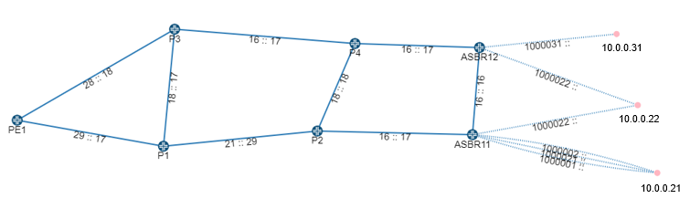
This example topology includes ten routers:
PE1 acts as the provider edge router
P1, P2, P3, and P4 act as core routers
ASBR11 and ASBR12 act as local ASBRs
10.0.0.31, 10.0.0.22 and 10.0.0.21 are BGP external peer routers
NorthStar has no information about the traffic past the ASBRs in this example, because the nodes are external to the local network; they belong to a different service provider. So it is also not possible for NorthStar to display congestion on the links past the ASBRs.
The goal is to be able to steer traffic to specific peer links. One of the paths is designated as “selected” by the routing protocol based on shortest path. Traffic engineering changes the selected path based on criteria other than shortest path. Use Junos OS show route commands to view the selected path and the advertised prefixes. Use NorthStar to override the selected path and reroute the traffic.
The remote ASBRs in ASs that are not managed by NorthStar are represented by red dots/IP addresses in Figure 1. NorthStar learns these ASBRs and the peer links connecting to them via BGP. The peer links connect a local ASBR (ASBR11, for example) to a remote ASBR (10.0.0.21, for example). An eBGP session runs across the peer links.
The NorthStar Route Reflector (in the Junos VM) learns of the remote ASBRs and peer links via BGP, and the NorthStar topology service instantiates the nodes and links and correlates them with other information it has, such as the interface on the local ASBR. NorthStar constructs one peer link when you configure an EPE node SID (egress-te-node-segment).
If you have more than one peer link between the same local-remote ASBR pair, you can configure an EPE link SID (egress-te-adj-segment) to differentiate between them. Each of these EPE link SIDs corresponds to a peer link in addition to the peer link for the EPE node SID. In this case, the EPE node SID represents load balancing across multiple peer links.
The following is an example BGP configuration, corresponding to ASBR11 in Figure 1.
    bgp {
        egress-te-sid-stats;
        group internal {
            type internal;
            local-address 10.0.0.11;
            family inet {
                segment-routing-te;
                unicast {
                    add-path {
                        send {
                            path-count 4;
                        }
                    }
                    extended-nexthop;
                    extended-nexthop-color;
                }
            }
            export next-hop-self;
            neighbor 10.0.0.10;
            neighbor 10.0.0.3;
            neighbor 10.0.0.12;
        }
        group NorthStar {
            type internal;
            family traffic-engineering {
                unicast;
            }
            export TE;
            neighbor 10.227.32.24 {
                local-address 10.227.34.144;
            }
        }
        group as1 {
            type external;
            multihop;
            local-address 10.227.34.144;
            family inet {
                segment-routing-te;
                unicast;
            }
            peer-as 2;
            neighbor 10.0.0.22 {
                multihop;
                local-address 10.0.0.11;
                export isis-to-bgp;
                egress-te-node-segment {
                    label 1000022;
                    egress-te-backup-segment {
                        label 1000021;
                    }
                }
            }
            neighbor 10.0.0.21 {
                multihop;
                local-address 10.0.0.11;
                export isis-to-bgp;
                egress-te-node-segment {
                    label 1000021;
                    egress-te-backup-segment {
                        label 1000022;
                    }
                }
                egress-te-adj-segment asbr11-asbr21 {
                    label 1000001;
                    next-hop 10.11.21.21;
                    egress-te-backup-segment {
                        label 1000002;
                    }
                }
                egress-te-adj-segment asbr11-asbr21-2 {
                    label 1000002;
                    next-hop 10.11.21.21;
                    egress-te-backup-segment {
                        label 1000001;
                    }
                }
            }
        }
The Junos OS show route advertising-protocol bgp neighbor-address command can be helpful for troubleshooting as the output shows the routing information being advertised to the neighboring router. Also, the netconfd.log is available for troubleshooting.
Configure add-path
To support the necessity of creating one BGP static route per tunnel color-prefix combination (due to a Junos OS limitation), you must configure add-path on the iBGP connection sending from the ASBR side and receiving on the PE side. This requires the following configuration:
On the ASBR side:
[edit protocols bgp group internal family inet unicast add-path]
         send {
             path-selection-mode {
                 all-paths;
             }
             path-count 64;
         }
[edit protocols bgp group internal]
      multipath;
On the PE side:
[edit protocols bgp group internal family inet unicast]
         add-path {
             receive;
         }
“Path-count 64” limits the number of PEs that a given prefix can be steered for to 64 minus the number of eBGP routes for the prefix. Currently, there is no notification if a requested demand-LSP binding would require creating more routes than would be exported. That kind of notification, as well as add-path support in the NorthStar REST API, are planned for a future NorthStar release.
The add-path configuration is also important for ensuring that static BGP steering routes do not affect unsteered traffic because without add-path, only the selected route is exported via BGP. In that case, the routes that are selected would be based on configured preference, and that could cause unsteered traffic to deviate from the IGP or BGP best path.
Enable PRPD
PRPD enables NorthStar to push the mapping using the PRPD client at the local ASBR. PRPD must be enabled, both in NorthStar and in the router configuration.
To enable PRPD in NorthStar, use the following procedure:
Navigate to Administration > Device Profile .
In the device list, click on a device that will be used for EPE and select Modify.
In the General tab of the Modify Device window, the login and password credentials must be correct for NorthStar to access the router.
In the Access tab of the Modify Device window, check Enable PRPD, and enter the port on the router that NorthStar will use to establish the PRPD session. Port 50051 is the default, but you can modify it. If you leave the PRPD IP field empty, the router ID (router’s loopback address) is used. The Access tab is shown in Figure 2.
Note:The PRPD IP address and the IP address in the
grpc
clear-text address
statement on the router (described shortly) should match.Figure 2: Modify Device Window for Enabling PRPD, Access Tab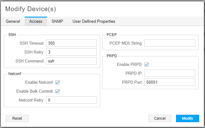
Click Modify to save your changes, and repeat for each device that will be used for EPE.
To enable the PRPD service on the router, use the following procedure:
Add the following configuration statements to the router configuration. The values are examples only:
set system services extension-service request-response grpc clear-text address 10.0.0.11
set system services extension-service request-response grpc clear-text port 50051
set system services extension-service request-response grpc max-connections 10
The IP address is typically the loopback address of the router; it should match the PRPD IP you configured in the device profile in NorthStar. The port number must match the one you entered in the device profile in NorthStar. The max-connections value is the total number of connections the router can receive from other clients. NorthStar will use one of those connections.
Make sure you have the BGP protocol enabled on the router.
For NorthStar to learn and display the BGP routes associated with each router, configure a policy with these statements (example policy is called “monitor”):
set policy-options policy-statement monitor then analyze
set policy-options policy-statement monitor then next policy
Then add
import monitorunder the BGP configuration.If configured successfully, you should be able to right-click on a node in the Node tab of the network information table and select View Routes to see the routing table for that node. Figure 3 shows an example. Only routing tables for nodes where PRPD is Up can be viewed in this way.
Figure 3: Routing Table Example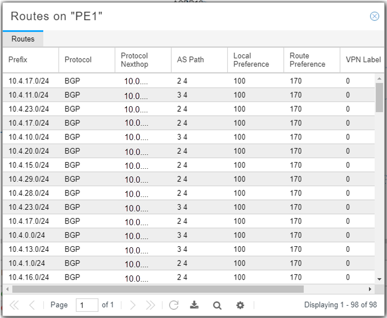
You can view the PRPD Status in the network information table (Node tab) as either Up or Down. If the PRPD Status is unexpectedly Down, check the device profile in NorthStar, and the router configuration, including whether BGP protocol is enabled.
Manual Rerouting Using SRTE Color Provisioning
In the sample topology shown in Figure 1, source node PE1 is sending traffic to destination prefix 10.4.3.0/24, which was advertised by nodes 10.0.0.21, 10.0.0.22, and 10.0.0.31. From PE1’s perspective, the preferred route is to ASBR11. From ASBR11’s perspective, the preferred destination node is 10.0.0.21. So before any rerouting, PE1 is sending traffic to node 10.0.0.21 via ASBR11.
To reroute the traffic from ASBR11 to destination node 10.0.0.22 (instead of 10.0.0.21), you would:
Provision a NETCONF or PCEP SRTE colored LSP
Map the demand using the PRPD client
Provisioning NETCONF SRTE or PCEP Colored LSPs
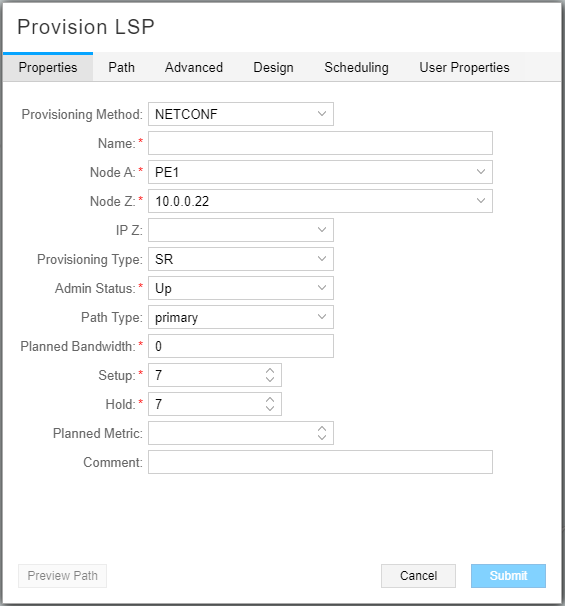
Select Network Management > Topology . From the network information table, Tunnel tab, click Add.
For this example, we provision an SR LSP using NETCONF from PE1 to 10.0.0.22. In Figure 4 the provisioning method is NETCONF and the provisioning type is SR.
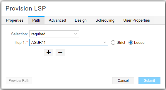
On the Path tab, select “required” in the Selection field, and specify that the traffic is to go through ASBR11. Figure 5 shows the Path tab of the Provision LSP window.
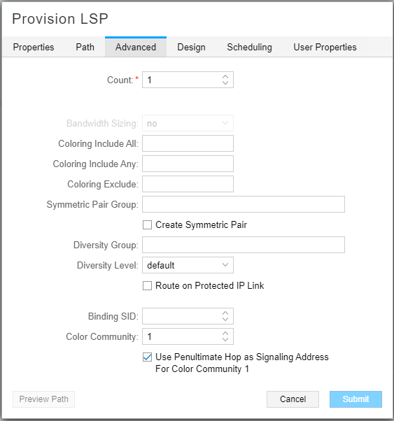
In the Advanced tab, specify the Color Community and check Use Penultimate Hop as Signaling Address for Color Community. In our example, the penultimate hop is ASBR11. Figure 6 shows the Advanced tab of the Provision LSP window.
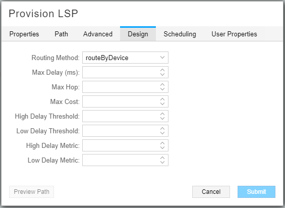
On the Design tab, select “routeByDevice” as the Routing Method to minimize the need for static SIDs in the path.Figure 7 shows the Design tab of the Provision LSP window.
Because the LSP is provisioned using NETCONF, NETCONF pushes the configuration to the router. The LSP entry in the Tunnel tab of the network information table shows the new destination address. NorthStar pushes the hop-by-hop route in the form of segment (SID) labels.
On the source node (node A), you can use the following Junos OS show commands:
To see the segment list:
show configuration protocols source-packet-routing.To see the final destination with the color designation, the state (Up/Down), and the LSP name:
show spring-traffic-engineering lsporshow configuration protocols source-packet-routing.
Mapping the Demand Using the PRPD Client
The following sections describe creating the demands and mapping them to SRTE colored LSPs.
Demands Created by Netflowd
The netflowd process analyzes traffic from the router and displays it in the Demands tab in the network information table. By default, Netflow aggregates traffic by PE, but for EPE, you want the traffic aggregated by prefix. To configure this, access the NorthStar CLI as described in Configuring NorthStar Settings Using the NorthStar CLI in the NorthStar Controller/Planner Getting Started Guide, and use the set northstar analytics netflowd aggregate-by-prefix always command.
Mapping the Demands
To map a demand, select it in the network information table (Demand tab) and click Modify to display the Modify Demand window. Select the LSP Mapping tab as shown in Figure 8.
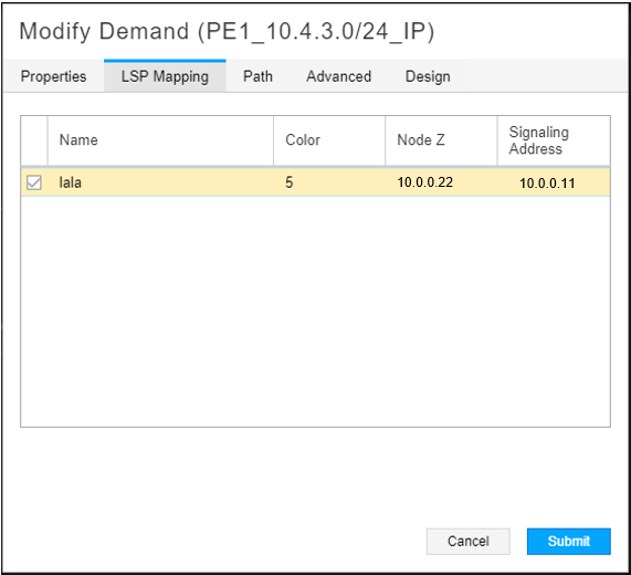
Click the check box beside the LSP to which you want the demand routed. In this release, you can only select one LSP. In our example, this would be the new SR LSP we created. Click Submit. NorthStar pushes the mapping via the PRPD client.
You can use the show route command
to confirm that the preferred path has changed as you specified.
To reverse the mapping, you can access the Modify Demand window again and deselect the check box for the LSP in the LSP Mapping tab. You can also delete the demand.
Mapping Admin Group Bits into User-Defined Names
(Admin only) NorthStar automatically discovers admin group bits associated with a link/LSP. Prior to NorthStar 6.2.0, this information was displayed in bits (i.e. bit0, bit1) in the web UI. Starting in NorthStar 6.2.0, you can assign a meaningful name to the admin group bits (0-31). For example, you might want to map an admin group to a network region such as San Francisco or New York, where each region is given its own bit name. Or, you can map each admin group to a color so that you can easily differentiate the different traffic routes in the display. Once defined, the link/LSP admin group is displayed in the topology map with its corresponding name.
To map an admin group bit into a user-defined name:
Select Administration > Admin Group.
Enter a name for the corresponding bit (0-31) and click Save. For example, in Figure 9, bit 0 is mapped to blue and bit 1 is mapped to green.
Figure 9: Mapping Admin Group Bits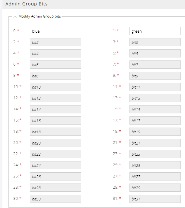
After you set the mapping, the admin group bit names that you specified appear in the network management table under the color columns. If you do not specify a name, NorthStar uses the default naming (bit0, bit1, etc).
To see the admin group names in the display, right-click the blank space in the topology map and click the Link Label > TE Color A::Z check boxes. The named/colored links then appear in the topology map as shown in Figure 10.
Note:Admin group names do not appear in the display appear for Tunnels.
Figure 10: Admin Group Topology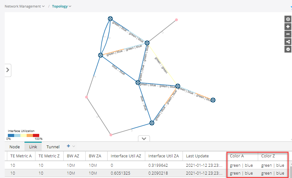
Filtering Admin Groups
In the network information table, you can filter admin groups in the Link and Tunnel tabs by activating a filter on any column (Figure 11).The filtering option allows you to filter the admin group bit names that show in the topology map. For example, to filter only links with admin group “blue”, hover over the Color A or Color Z column heading in the Link tab, click the down arrow that appears, and enter blue in the filter box. Only the links colored blue will show in the network information table.
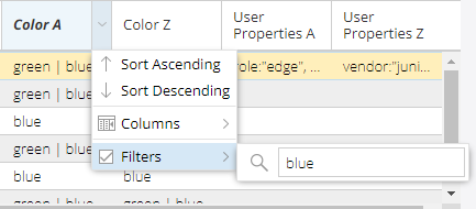
Admin groups in the link tab are filtered from the Color A and Color columns. Admin groups in the Tunnel tab are filtered from the Coloring Include All, Coloring Include Any, and Coloring Exclude columns.
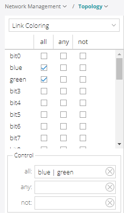
You can also filter links from the Link Coloring option in left pane drop-down menu (Figure 12). There are three conditions you can filter by (all, any, not). For example, if you check the "blue and green” boxes under the “all” condition, every link named those colors will appear in the map.
There is an Advanced Filter in the Network Information bottom tool bar (magnifying-glass icon). This filter allows you to enter your own filtering criteria and gives you more control as compared to using a regular filter. The advanced filter is not available for tunnels.
For more information about filtering, including descriptions about the various filtering options, see Sorting and Filtering Options in the Network Information Table.
NorthStar’s Approach to Steering Using Static BGP Routes
The NorthStar EPE steering capability installs static BGP routes with color communities to select tunnels and route target communities to select PEs originating those tunnels. These static routes are installed at the egress ASBR with the peer link that the prefix is to be steered include the route targets of the PEs that are to steer the traffic to a peer link of the ASBR. The color of the static route is the color of the tunnels on the PEs that guide the traffic to the peer link where the traffic is to be steered.
Currently, Junos only supports one color in a route for steering purposes, so NorthStar must install a static route for each prefix-color combination needed. NorthStar includes a configuration parameter to change its behavior to install a single static route for a steered prefix that collects together all the PE route targets and tunnel colors involved in steering a prefix to a peer link of the egress ASBR. This will allow NorthStar to be more efficient with static routes in the future if JUNOS later supports multiple colors in a single route for steering purposes.
The static routes installed by NorthStar have lower preference than routes learned from BGP, so unsteered traffic does not use those roues. Instead, it uses only the BGP routes, and takes the IGP shortest path. The static routes have an empty AS path however, so where they are imported when learned from BGP, they will be selected because their AS paths will be shorter than any route learned for eBGP. The static routes are only distributed internally in the AS by iBGP and must be filtered in the export policy of all eBGP sessions. Imagine the “trombones”, micro-loops, and route flapping that could result if the static routes were to be exported via eBGP!
The static routes are distributed by iBGP to all the ingress PEs. The PE uses an import policy to limit the import of static routes to those that include the PE’s route target. The color of the route indexes the SID list in inetcolor.0. The SID list is used on the route to steer the prefix to a peer link. The empty AS path ensures the route will be selected over all other BGP routes from different ASs, so the PE will select the imported static route for activation. This is the mechanism that allows you to steer traffic on PEs by injecting static routes on the ASBRs with the peer link to which the traffic is to be steered.
Reference Network
It might be helpful to examine the reference network used to test the EPE steering and planning functionality, and take a look at an example based on it. Figure 13 illustrates the network topology.
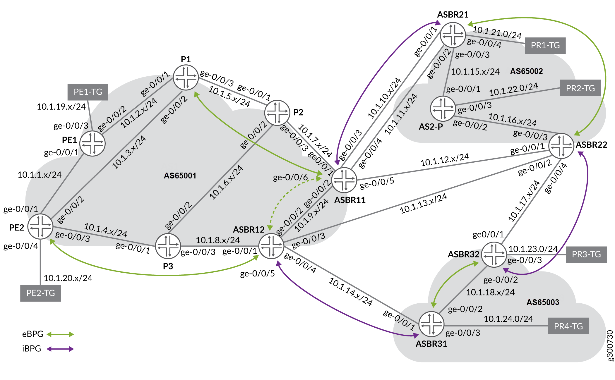
In this topology, the management subnet is 10.227.34.0/24.
The test setup has 3 ASs: AS1 managed by NorthStar, and AS2 and AS3 which are peer ASs. In a more realistic setup there would be a route reflector for iBGP sessions. If AS1 is a transit provider, there would be an iBGP session between ASBR11 and ASBR12, but for purposes of testing, we omit this iBGP session to more easily see the results of EPE steering.
There are two PEs (PE1 and PE2) with corresponding traffic generators (PE1-TG and PE2-TG). The traffic generators send traffic entering the respective PEs.
There are four prefixes with corresponding traffic generators that receive traffic for the corresponding prefixes:
10.1.21.0/24: PR1-TG
10.1.22.0/24: PR2-TG
10.1.23.0/24: PR3-TG
10.1.24.0/24: PR4-TG
The traffic generators for the prefixes are distributed among the peer ASs. Some are connected directly to an ASBR; others are connected to a non-ASBR.
With two PEs and four prefixes, there are eight possible traffic demands you could create in this network as shown in Table 1.
Demand Name |
Prefix |
Node A |
Node Z |
IP A |
IP Z |
Bandwidth |
|---|---|---|---|---|---|---|
epe3-PE1_10.1.21.0/24_IP |
10.1.21.0/24 |
epe3-PE1 |
epe3-ASBR11 |
10.0.0.10 |
10.0.0.11 |
987.6K |
epe3-PE2_10.1.21.0/24_IP |
10.1.21.0/24 |
epe3-PE2 |
epe3-ASBR11 |
10.0.0.20 |
10.0.0.11 |
946.9K |
epe3-PE1_10.1.22.0/24_IP |
10.1.22.0/24 |
epe3-PE1 |
epe3-ASBR11 |
10.0.0.10 |
10.0.0.11 |
2.9M |
epe3-PE2_10.1.22.0/24_IP |
10.1.22.0/24 |
epe3-PE2 |
epe3-ASBR12 |
10.0.0.20 |
10.0.0.12 |
3.0M |
epe3-PE2_10.1.23.0/24_IP |
10.1.23.0/24 |
epe3-PE2 |
epe3-ASBR12 |
10.0.0.20 |
10.0.0.12 |
4.9M |
epe3-PE1_10.1.23.0/24_IP |
10.1.23.0/24 |
epe3-PE1 |
epe3-ASBR12 |
10.0.0.10 |
10.0.0.12 |
4.9M |
epe3-PE1_10.1.24.0/24_IP |
10.1.24.0/24 |
epe3-PE1 |
epe3-ASBR12 |
10.0.0.10 |
10.0.0.12 |
7.2M |
epe3-PE2_10.1.24.0/24_IP |
10.1.24.0/24 |
epe3-PE2 |
epe3-ASBR12 |
10.0.0.20 |
10.0.0.12 |
6.9M |
You run iBGP between PEs and ASBRs in AS1, and eBGP across the peer links. There are five peer links visible to NorthStar for EPE:
ASBR11-ASBR21a
ASBR11-ASBR21b
ASBR11-ASBR22
ASBR12-ASBR22
ASBR12-ASBR31
This setup allows the ten EPE tunnels shown in Table 2:
Tunnel Name |
Node A |
Node Z |
IP A |
IP Z |
Color |
|---|---|---|---|---|---|
PE2-ASBR11-ASBR21a |
epe3-PE2 |
ASBR21 |
10.0.0.20 |
10.0.0.21 |
1 |
PE1-ASBR11-ASBR21a |
epe3-PE1 |
ASBR21 |
10.0.0.10 |
10.0.0.21 |
1 |
PE2-ASBR11-ASBR21b |
epe3-PE2 |
ASBR21 |
10.0.0.20 |
10.0.0.21 |
2 |
PE1-ASBR11-ASBR21b |
epe3-PE1 |
ASBR21 |
10.0.0.10 |
10.0.0.21 |
2 |
PE1-ASBR11-ASBR22 |
epe3-PE1 |
ASBR22 |
10.0.0.10 |
10.0.0.22 |
3 |
PE2-ASBR11-ASBR22 |
epe3-PE2 |
ASBR22 |
10.0.0.20 |
10.0.0.22 |
3 |
PE1-ASBR12-ASBR22 |
epe3-PE1 |
ASBR22 |
10.0.0.10 |
10.0.0.22 |
4 |
PE2-ASBR12-ASBR22 |
epe3-PE2 |
ASBR22 |
10.0.0.20 |
10.0.0.22 |
4 |
PE2-ASBR12-ASBR31 |
epe3-PE2 |
ASBR31 |
10.0.0.20 |
10.0.0.31 |
5 |
PE1-ASBR12-ASBR31 |
epe3-PE1 |
ASBR31 |
10.0.0.10 |
10.0.0.31 |
5 |
All remote ASBRs export one route for each prefix into the eBGP connections they have with ASBRs in AS1. Note that these routes have a variety of AS paths, including:
2
3
2 3
3 2
Tunnel Requirements
As of NorthStar 5.1, the only scenario available for EPE is SR tunnels provisioned via NETCONF because colored SR tunnel provisioning is not yet available via PCEP.
One issue with NETCONF provisioning of SR tunnels is that tunnel routes might depend on dynamic adjacency SIDs that will change when links bounce or routing protocols are restarted. This happens, for example, when route policy is changed. If SIDs change for NETCONF-provisioned SR tunnels, they are lost for use by NorthStar and must be deleted and reprovisioned. For this reason, it is required that NETCONF-provisioned colored SR tunnels depend on only statically provisioned SIDs.
The primary way to achieve this is to use a loose hop as the local ASBR and then a strict hop to the peer link. This works because SID compression done by NorthStar or the router will include only the ASBR node SID, and peer adjacency or node SID in the segment list. All of these are static.
In Figure 14, the Modify LSP window in the NorthStar Controller UI shows an example of a tunnel that meets the EPE requirements. The provisioning method for this tunnel is NETCONF. On the Properties tab shown, note that the Z node is the remote ASBR and the provisioning type is SR.
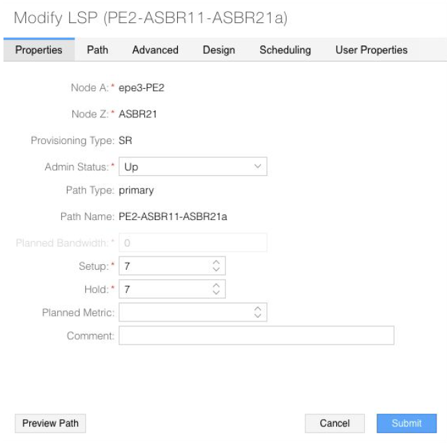
The following additional tunnel requirements for EPE are also adhered to:
The last hop must be a strict hop to a peer link (configured on the Path tab).
The tunnel must have a color community assigned and use the penultimate hop as the signalling address (configured on the Advanced tab). The color need only be unique among the tunnels for a given PE, but colors can be reused on different PEs.
The selection of routeByDevice as the routing method (Design tab) allows the Junos OS to do SID compression, eliminating the need for statically configured adjacency SIDs to just the adjacencies leaving the PEs.
NorthStar Steering Command Functionality
When a demand is mapped to an LSP, the NorthStar PCS sends a request to the PRPD client, which forwards it on to the ASBR where the binding tunnel exits the AS managed by NorthStar on a peer link. The steering command installs or updates a BGP static route with the following properties:
A path cookie unique among all route cookies for the ASBR.
The PRPD documented role of path cookies is to identify the owner of the route so different PRPD clients cannot interfere with each other’s routes.
The PCS allocates a path cookie to a static route by searching for an unused path cookie starting at the value specified by the target-tag-cookie-range-start setting. The default for this setting is 100. You can change the value by accessing the NorthStar CLI as described in Configuring NorthStar Settings Using the NorthStar CLI in the NorthStar Controller/Planner Getting Started Guide. Use the set northstar path-computation-server bgp-steering target-tag-cookie-range-start command.
The prefix of the traffic demand.
Communities:
The route target for the PE originating the tunnel in the form target:router-ip:42, configured by the PCServer_PRPDTargetTag parameter in the internal cache. The default is 42. .
The color of the tunnel in the form color:0:color.
The next hop, which is the IP address of the ASBR on the other end of the peer link.
The route preference, which is 171. This is less preferable than BGP routes which have a default preference of 170.
A local preference of 100.
asPath is empty/none.
MED (multi-exit discriminator) is none.
It is possible to allocate color tunnels so that a color is used repeatedly for tunnels on different PEs. For example, refer back to Table 2. For a given peer link, both PEs use the same color. Tunnels to ASBR11-ASBR21a use color 1, tunnels to ASBR12-ASBR31 use color 5, and so on. When this is the case, if there is more than one demand-LSP binding for the same prefix to the same egress ASBR, you can affect the required steering with a single static route for the prefix. The route would have the color, and collects all the route targets for the PEs that need to do the steering. The PCS will do this sort of aggregation of route targets in the static routes, adding and removing route targets from an existing compatible static route rather than creating a separate route for each route target.
Required PE Import Policy
Because you want only the PE where you are steering to import the steering route, you use the PE’s IP in the route target and require an iBGP import policy. In the example setup, PE n has IP address 10.0.0.n0:
[edit]
admin@PEn# show policy-options

policy-statement targeted-color {
    term accept-my-target {
        from community my-target;
        then accept;
    }
    term reject-other-targets {
        from community any-target;
        then reject;
    }
    term accept-all-else {
        then accept;
    }
}
community any-target members target:*:*;
community my-target members target: 10.0.0.n0 :42;

[edit]
admin@PEn# show protocols bgp group internal
type internal;
local-address 10.0.0.n0 ;
import targeted-color ;
Binding Example
Consider an example in which the traffic demand from 10.0.0.10 (PE1) to 10.1.21.0/24 is bound to tunnel PE1-ASBR11-ASBR21a. The tunnel has color 1. ASBR21’s IP address is 10.0.0.21.
ASBR11
On ASBR11, the route should look like this:
admin@epe3-ASBR11> show route 10.1.21

inet.0: 39 destinations, 55 routes (39 active, 0 holddown, 0 hidden)
+ = Active Route, - = Last Active, * = Both

10.1.21.0/24 *[BGP/170] 03:55:29, localpref 100, from 10.0.0.21
                AS path: 2 I, validation-state: unverified
                 to 10.1.10.2 via ge-0/0/3.0
               > to 10.1.11.2 via ge-0/0/4.0
               [BGP/170] 03:55:25, MED 30, localpref 100, from
10.0.0.22
                AS path: 2 I, validation-state: unverified
               > to 10.1.12.2 via ge-0/0/5.0
               [BGP-Static/171/-101] 00:00:07, metric2 0
                 to 10.1.10.2 via ge-0/0/3.0
               > to 10.1.11.2 via ge-0/0/4.0
The BGP static route has preference 171, so it would never be preferred over the BGP learned routes. This ensures that the BGP static route is used for steering only and won’t interfere with unsteered traffic that arrives on the ASBR. The route target and color communities are deeper in the extensive output.
admin@epe3-ASBR11> show route 10.1.21 extensive | match commun
     Communities:
     Communities:
     Communities: target:10.0.0.10:42 color:0:1
                Communities: target:10.0.0.10:42 color:0:1
PE1
On PE1, the route is imported and becomes the active route due to its shortest AS path. Because we set an empty AS path in the static route, it the PE sees it as an internal route, so it is activated above all others.
admin@epe3-PE1> show route 10.1.21

inet.0: 35 destinations, 53 routes (35 active, 0 holddown, 0 hidden)
+ = Active Route, - = Last Active, * = Both

10.1.21.0/24         *[BGP/170] 00:00:58, localpref 100, from 10.0.0.11
                        AS path: I, validation-state: unverified
                       > to 10.1.2.2 via ge-0/0/2.0, Push 1000001, Push 800011(top)

                      [BGP/170] 03:29:58, localpref 100, from 10.0.0.11
                        AS path: 2 I, validation-state: unverified
                       > to 10.1.2.2 via ge-0/0/2.0, Push 800011

                      [BGP/170] 03:29:58, MED 30, localpref 100, from 10.0.0.11
                        AS path: 2 I, validation-state: unverified
                       > to 10.1.2.2 via ge-0/0/2.0, Push 800011

                      [BGP/170] 03:30:13, MED 30, localpref 100, from 10.0.0.12
                        AS path: 2 I, validation-state: unverified
                       > to 10.1.1.2 via ge-0/0/1.0, Push 800012

                      [BGP/170] 03:30:13, localpref 100, from 10.0.0.12
                        AS path: 3 2 I, validation-state: unverified
                       > to 10.1.1.2 via ge-0/0/1.0, Push 800012
This route is imported because it has the router’s route target:
admin@epe3-PE1> show route 10.1.21 extensive |match commun

Communities: target:10.0.0.10:42 color:0:1
As specified in the policy:
[edit]
admin@epe3-PE1# show policy-options

policy-statement targeted-color {
    term accept-my-target {
        from community my-target;
        then accept;
    }
    term reject-other-targets {
        from community any-target;
        then reject;
    }
    term accept-all-else {
        then accept;
    }
}
community any-target members target:*:*;
community my-target members target:10.0.0.10:42 ;
Because the route has a color community, the SID list is pushed from the entry in inetcolor.0 with the matching color:
admin@epe3-PE1> show route table inetcolor.0

inetcolor.0: 5 destinations, 5 routes (5 active, 0 holddown, 0 hidden)
+ = Active Route, - = Last Active, * = Both

10.0.0.11-1c/64
        *[SPRING-TE/8] 03:33:35, metric 1, metric2 0
           > to 10.1.2.2 via ge-0/0/2.0, Push 1000001, Push 800011(top)
PE2
The route is also received on PE2, but it is hidden. The import policy rejects it due to its different route target. This ensures that steering routes do not interfere with unsteered traffic on the EPE side:
admin@epe3-PE2> show route 10.1.21 hidden

inet.0: 36 destinations, 54 routes (36 active, 0 holddown, 1 hidden )
+ = Active Route, - = Last Active, * = Both

10.1.21.0/24         [BGP ] 00:02:07, localpref 100, from 10.0.0.11
                       AS path: I, validation-state: unverified
                      > to 10.1.3.2 via ge-0/0/2.0, Push 1000001, Push 800011(top)

admin@epe3-PE2> show route 10.1.21 hidden extensive | match Comm

                Communities: target:10.0.0.10:42 color:0:1

admin@epe3-PE2> show route 10.1.21 hidden extensive | match Reason

                Inactive reason: Unusable path
                Hidden reason: rejected by import policy
For reference, this is the policy that rejects the route:
[edit]
admin@epe3-PE2# show policy-options

policy-statement targeted-color {
    term accept-my-target {
        from community my-target;
        then accept;
    }
    term reject-other-targets {
        from community any-target;
        then reject;
    }
    term accept-all-else {
        then accept;
    }
}
community any-target members target:*:*;
community my-target members target:10.0.0.20:42 ;
Monitoring Steering Commands
The PCS associates each steering route with the underlying BGP route, showing that the ASBR at the other end of the peer link can send the prefix on toward its final destination without creating a routing loop. Referring to the example in the previous section:
admin@epe3-ASBR11> show route 10.1.21

inet.0: 39 destinations, 55 routes (39 active, 0 holddown, 0 hidden)
+ = Active Route, - = Last Active, * = Both

10.1.21.0/24         *[BGP/170] 04:37:17, localpref 100, from 10.0.0.21
                        AS path: 2 I, validation-state: unverified
                         to 10.1.10.2 via ge-0/0/3.0
                       > to 10.1.11.2 via ge-0/0/4.0

                      [BGP/170] 04:37:13, MED 30, localpref 100, from 10.0.0.22
                        AS path: 2 I, validation-state: unverified
                       > to 10.1.12.2 via ge-0/0/5.0

                      [BGP-Static/171/-101] 00:00:03, metric2 0
                         to 10.1.10.2 via ge-0/0/3.0
                       > to 10.1.11.2 via ge-0/0/4.0
The steering route depends on the existence of the active route (a steering route can also depend on an inactive route). If the dependent route goes away, traffic on the tunnel could be routed back to ASBR11, or dropped.
The PCS monitors the route on which the steering route is dependent and automatically removes the steering route should the dependent route disappear.
If the dependent route re-appears, the PCS reinstalls the steering route as long as the demand LSP binding is still present. This operation is dampened to prevent thrashing if the network is flapping. A backoff is implemented, delaying up to 15 minutes between attempts to install a steering route. This is well established PCS behavior for network provisioning operations. When a steering route is in this process, the controller status for the demand with the LSP binding is a message that begins with “Provisioning Rescheduled”.