Viewing OSPF Areas
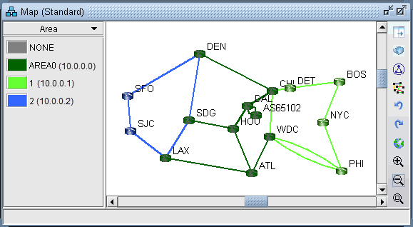
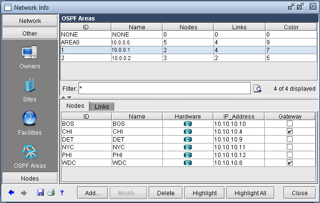
To illustrate one method of adding Inter-Area LSP tunnels to a network, we will use the network shown in Figure 309. There are three OSPF Areas in this network: AREA0, 1 and 2. This information can also be retrieved by going to Network > Protocols > OSPF Areas in View mode, or Modify > Protocols > OSPF Areas in Modify mode.
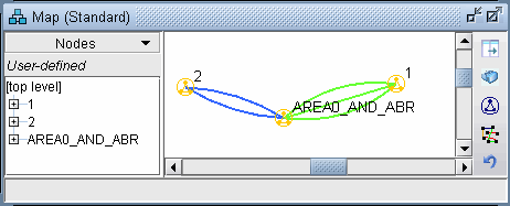
To facilitate the viewing of the OSPF areas, you can first group nodes by OSPF Area. Right-click on the Map window and choose Grouping > AutoGroup from the popup menu. In the AutoGroup window, first choose Area. Then, click Done.
The nodes are automatically grouped by Area and identified by Area ID. If you choose the Network Elements > Nodes legend from the top selection box to the left of the Map, you will see a tree-view structure of the newly created groups. Clicking on the groups in the tree view will expand the group and reveal the member nodes. Alternatively, they can be expanded by right-clicking the Map window and selecting Grouping>Expand All.