FRR Design
Once you have specified which tunnels (or links) require FRR backup tunnel protection, you can then proceed to run the FRR Design. The FRR Design feature is powerful and flexible. Not only does it automate the design, but it also allows you to specify a number of parameters to control various aspects of the design.
You should have already specified which LSP tunnels require FRR protection, or have enabled the FRR flags for the desired links as mentioned in the previous sections. As mentioned in the prerequisites, you should also have created any facilities and sites if you want site-diverse or facility-diverse paths.
Switch to Design mode by clicking on the Design mode button. This feature is only available in Tunnel layer mode. If you are not in Tunnel layer, you will automatically be switched into that layer first.
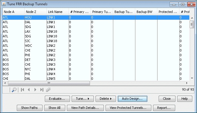
Then select Design > TE Tunnels > FRR Design to open up the Tune FRR Backup Tunnels window.

If there are no FRR backup tunnels, a popup window will be displayed providing the option to automatically generate the FRR backup tunnels. There are two options for design:
You can either allow the program to perform an automatic design for all the tunnels and links requesting FRR backup protection in this window by answering yes to the popup explained in the previous step. (If you answer no, you can still come back to this automatic design option by clicking the Auto Design button.)
Alternatively, you can selectively view or tune FRR Backup Paths from the Tuning window by selecting the entry or entries of interest and then selecting Tune>Selected. For example, you can choose to create an FRR link backup tunnel for an entry of type Link with a particular Link Name for the link to protect, or create an FRR node backup tunnel for an entry of type Node with a particular Protected Node.
Tune FRR Backup Tunnels Fields
Node A, Node Z: The source and destination node pair for a potential FRR Backup tunnel.
Link Name: For Link Protection tunnels, this is the name of the link being protected. For Node Protection tunnels, this is the name of the link between the Point of Local Repair (PLR) router and the node being protected.
# Primary Tunnels: Indicates the number of FRR-enabled primary tunnels traversing through the link between Node A and Node Z.
Primary Tunnel BW: Indicates the total bandwidth of all the FRR-enabled primary tunnels traversing through the link between Node A and Node Z.
Backup Tunnel: The name of the newly created backup tunnel. This is automatically assigned by NorthStar Planner. The backup tunnel name typically begins with “FRRLK” or “FRRND”.
Backup BW: The amount of bandwidth the newly created backup tunnel can protect.
Protected Pool: Indicates the type of primary tunnel that the newly created backup tunnel can protect: Sub-pool or Global-pool
# Prot Prim Tun: Indicates the number of FRR-enabled primary tunnels actually carried/protected by the backup tunnel.
Type: Indicates the type of backup tunnel: Link Protected or Node Protected.
Protected Node: For FRR Node Protection tunnels, this indicates the node whose failure is being protected against.
Prot Prim Tun BW: Indicates the total bandwidth of the FRR-enabled primary tunnels actually carried by the backup tunnel.
RSVP BW: The actual bandwidth reserved for the tunnel
Design BW: The bandwidth value that is used for constraint-based routing to determine the placement of the backup tunnel during a design. This can be different from the RSVP BW actually configured on the backup tunnel and the Backup BW.
Div Level: Indicates whether the backup tunnel has a route that is Link-Diverse, Site-Diverse or Facility-Diverse from the protected path. Use the Evaluate button to update the diversity level for a particular type of diversity (Facility, Link, or Site)
Path Violation: Indicates whether there is a path violation in the backup tunnel path
Backup Route: The route for the newly created backup tunnel, if one is found. If no route is found, then this field will say “Unplaced”.
Options
Evaluate: Updates the Div Level column to show the diversity level between the protected path and its backup tunnel. Available diversity evaluation options are Facility, Link, or Site. For example, if you want to see whether the protected path is on a facility-diverse path from its backup tunnel, select Facility.
Tune>Selected: Brings up a window with options for tuning the selected entries by creating or modifying the backup tunnel for that entry
Delete>Selected: Deletes the backup tunnel(s) listed in the selected entries
Auto Design: Brings up a window with options for creating backup tunnels for all entries
Show Paths: Displays paths of backup tunnel, protected segment, and protected tunnels. Select an entry with a Backup Tunnel and positive value for # Prot Prim Tun before clicking this button.
Show All: Displays node to node connections of all backup tunnels on the Map window.
View Path Details: Opens up a Tunnel window listing only the FRR backup tunnel
View Protected Tunnels: Opens up a Tunnel window listing only the primary FRR-enabled tunnels that the selected FRR backup tunnel protects.
Report: Saves the Tune FRR Backup Tunnels table into a comma separated report.
Note:The columns of the Tune FRR Backup Tunnels window can be customized. That is, you can choose just a subset of the many columns to appear. To access this feature, right click on a column header and choose Table Options from the popup menu.
Auto Design Parameters

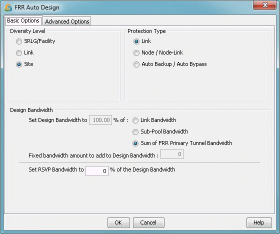
Diversity Level: Select Link, Site, or Facility diversity for the link being protected and its FRR backup tunnel to be routed on link-disjoint paths, site-disjoint paths, or facility-disjoint paths, respectively. For Site diversity, the FRR backup tunnel is to avoid, if possible, nodes that are in the same site as the link and its endpoints. Facility and Link diversity operate similarly. If Facility diversity level is selected, then the link and backup tunnel route should not intersect at any of the nodes or links defined in the facility. Recall that a facility is a user-defined group of nodes and links and is commonly used to represent Shared Risk Link Groups (SRLG). For more information, refer to Link, Link, Site and Facility Diverse Paths.
Protection Type: Specify Link or Node/Node-Link to indicate whether you wish to design FRR Link Protection or FRR Node Protection tunnels, respectively. Specify Auto Bypass to automate bypass creation for Juniper based on the configuration parameters on the interface.
Design Bandwidth (for Design/Placement): The Design Bandwidth is used for Design purposes only, to decide where to place the tunnel, and is not used to set the actual RSVP bandwidth. The backup tunnels will be placed by the program using constraint-based routing assuming that it would reserve a certain bandwidth along the tunnel route for the tunnel to be placed. However, once the placement is done, the actual tunnel’s RSVP bandwidth can be set to a different value, using the following Set RSVP Bandwidth option.
The Design Bandwidth is specified as a percentage of a Reference Bandwidth Source plus a fixed value. The Reference Bandwidth Source can be the (a) Link Bandwidth:the entire link bandwidth, (b) Sub-Pool Bandwidth: the subpool bandwidth allocated on the link (for Cisco only), or (c) Sum of FRR Primary Tunnel Bandwidth: the sum of the bandwidth of all primary FRR-enabled tunnels that the backup tunnel protects (for Juniper). By adjusting the % and fixed values (which default to the divpathbwpct and divpathbw in the dparam file), you can perform overbooking.
Note:Regarding option (b), if the Reference Bandwidth Source is set to Sub-Pool and if the protected link has no subpool partition, then a backup tunnel will not be designed.
Set RSVP Bandwidth to: Specifies the actual bandwidth for the backup tunnel, as a percentage of the Design bandwidth.
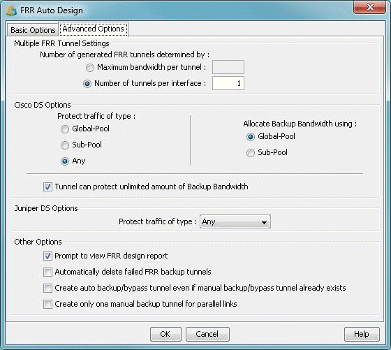
Multiple FRR Tunnel Settings: You can create multiple backup tunnels by specifying either:
Maximum bandwidth per tunnel: This is the maximum bandwidth allowed; tunnels will be split if the design bandwidth exceeds this value.
Number of tunnels per interface: You can specify directly how many backup tunnels to create on the interface with each tunnel equally sharing the design bandwidth.
Figure 3: FRR Design - Advanced Options Tab
Advanced Options for Cisco
Protect traffic of type: For the backup tunnels that are designed, you can specify the type of tunnel that they are to protect. If you specify Global-Pool, then the backup tunnels can only protect primary tunnels that are designated to carry Global-Pool traffic. If you specify Sub-Pool, then the backup tunnels designed can only protect primary tunnels designated to carry Sub-Pool traffic. If Any is specified, then the backup tunnels designed are allowed to carry either type of primary tunnel.
Note that if Global-Pool or Sub-Pool is specified, then the newly generated backup tunnel(s) will have “BKGP” or “BKSP”, respectively, listed in the tunnels’ Type field parameters. By looking at the tunnel type parameters, the Protected Tunnel Type can be identified. If there is no indication, then the default protected type is “Any”.
Allocate Backup Bandwidth using: This selection allows you to specify whether the backup bandwidth for the FRR backup tunnel should be allocated from the links’ Global-Pool or Sub-Pool at the time of failure.
If Sub-Pool is specified, then the newly generated backup tunnel(s) will have “GB” (Guaranteed Bandwidth) in their Type field. A backup tunnel that does not contain “GB” is by default using Global-Pool bandwidth.
Tunnel can protect unlimited amount of Backup Bandwidth: Indicates whether the amount of bandwidth the backup tunnel can protect is limited or unlimited. If checked, this option will allow all primary tunnels to be routed over the backup tunnel. This is the default. If unchecked, the backup bandwidth will be limited to the value set in the Design Bandwidth section of the Basic Options tab. This limit is effective at the time of failure when the backup tunnel is activated.
Note:Setting the Design Bandwidth to 0 is equivalent to allowing Unlimited backup bandwidth.
Advanced Options for Juniper
Protect traffic of type: For the backup tunnels that are designed, you can specify the type of tunnel that they are to protect. Values include Single-Class LSP, Multi-Class LSP, or Any. If Single-Class LSP is selected, you should then specify one of the resulting options: CT0, CT1, CT2, or CT3. If Multi-Class LSP is selected, enter in the percentage for each of the 4 classes. For more information about DiffServ-TE, seeDiffServ Traffic Engineering Tunnels Overview.
Other Options
Prompt to view FRR design report: Selecting this checkbox will cause the FRR Design report to be automatically displayed once an FRR Design or View/Tune Paths operation has completed. This report is saved to the Output Path in the File Manager under the name “FRRDSGNRPT.runcode”. To access it in the File Manager, right-click on the file and choose “Open in Report Viewer”. For more information on the FRR design report, see FRR Design Report.
