Cisco ISE Configuration for Third-Party Plug-in
Policy Enforcer's Cisco ISE Connector communicates with the Cisco Identity Services Engine server using the Cisco ISE API. As part of threat remediation, Policy Enforcer's Connector uses enforcement profiles. This section provides information for configuring Cisco ISE so that Policy Enforcer can invoke the appropriate enforcement profiles.
As part of the configuration, on Cisco ISE you will create two enforcement profiles, one for quarantine and one for terminate. Then you will use them in the Cisco ISE enforcement policy. Once Cisco ISE is configured, you will configure a Cisco ISE Connector on Policy Enforcer.
On Cisco ISE you will configure the following:
-
Change policy modes
-
Create an API client
-
Configure network profiles
-
Add a custom attribute
-
Configure authorization profiles
-
Set an authorization policy
On Cisco ISE, the Simple Mode policy model is selected by default. For creating an API client, Policy Sets should be enabled.
-
Navigate to Administration > System > Settings > Policy Sets and Enable Policy Sets mode.
You are prompted to login again after changing the mode.
Figure 1: Cisco ISE: Enable Policy Sets Mode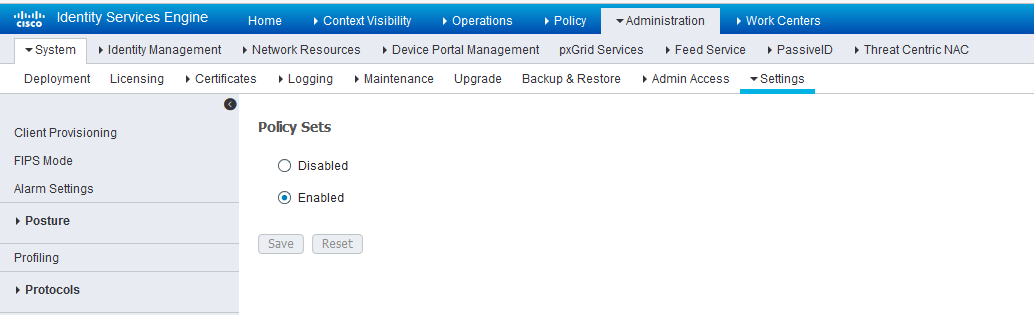
Create an API Client:
-
Create an Admin User and assign it to the following Admin
Groups: ERS Admin, MnT Admin.
Make note of the username and password. You will need them when you configure the connector portion in Policy Enforcer later on.
Figure 2: Cisco ISE: Create Admin User and Assign to Admin Groups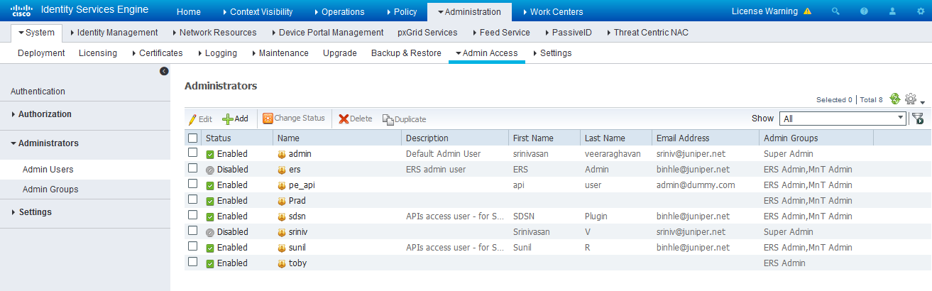
Enable the External RESTful Services API (ERS) for the Administration Node:
-
Navigate to Administration > System > Settings >ERS Settings and select Enable ERS for Read/Write.
-
Click Save.
Figure 3: Cisco ISE: Enable ERS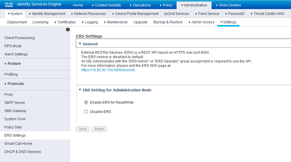
Configure network profiles:
Devices managed by ISE must support RADIUS CoA and have the proper network profiles assigned to handle the CoA commands sent by the ISE server:
-
Navigate to Administration > Network Resources > Network Device Profiles and verify the existing network device profile list.
If you are creating a new profile, proceed to the next step for information.
Figure 4: Cisco ISE: Network Device Profiles List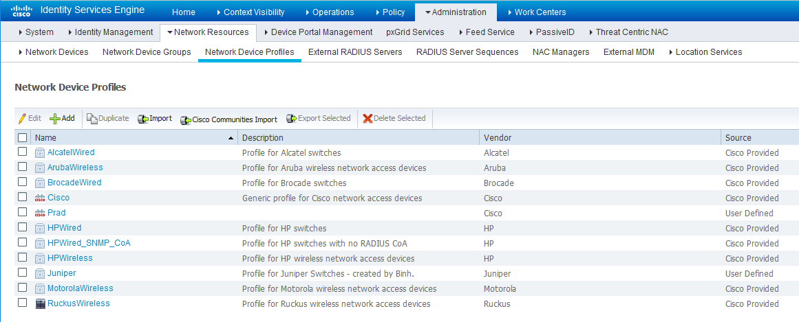
-
If you are configuring a new profile, you must minimally set the following:
-
Enable RADIUS and add a corresponding dictionary in the supported protocol list.
Figure 5: Cisco ISE: Network Device Profile, Enable RADIUS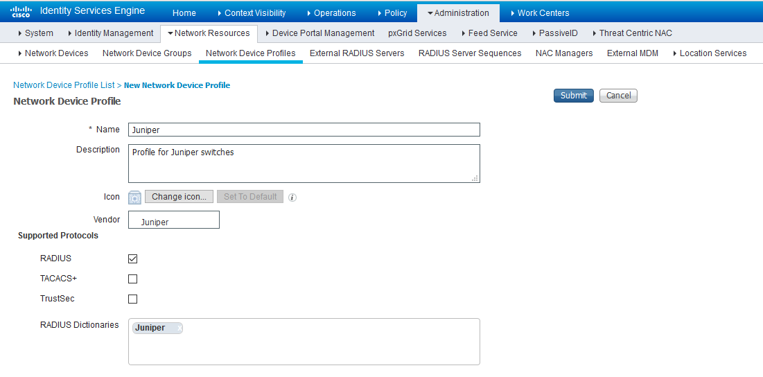
-
Enable and configure the Change of Authorization (CoA) according to the figure below.
Figure 6: Cisco ISE: Configure Change of Authorization (CoA)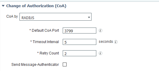
-
Configure the Disconnection and Re-authenticate operation with the proper RADIUS attributes and vendor specific VSA to handle the standard disconnect and reauthenticate operations. Below is the sample configuration for Juniper’s EX devices.
Figure 7: Sample Configuration for Juniper EX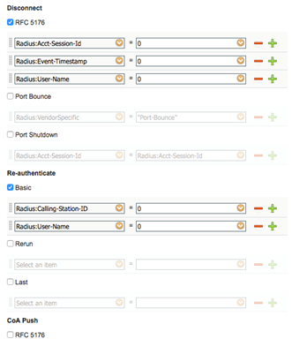
-
Configure a custom attribute.
-
Navigate to Administration > Identity Management > Settings > Endpoint Custom Attribute and add attribute sdsnEpStatus with type string.
Figure 8: Cisco ISE: Add Attribute sdsnEpStatus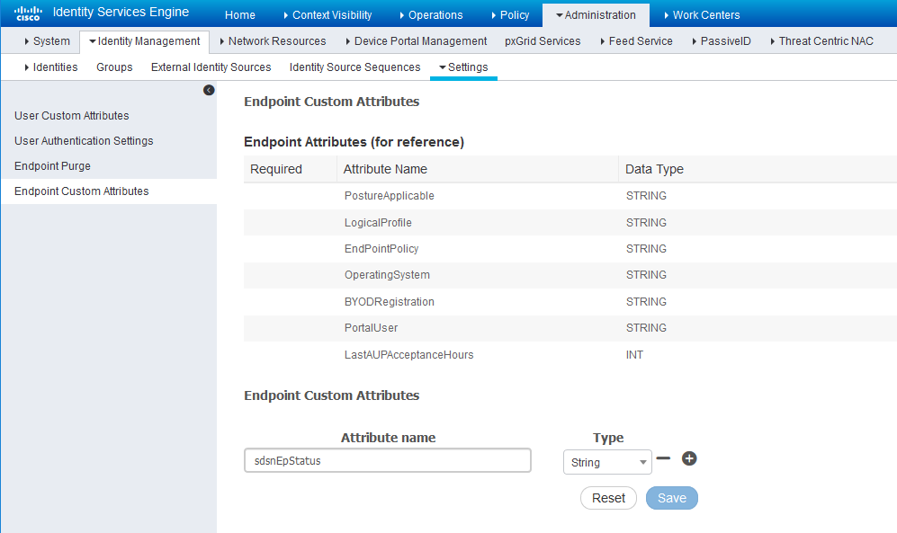
-
Verify the attribute under Policy > Policy Elements > Dictionaries > System > Endpoints.
Figure 9: Cisco ISE: Verify Attribute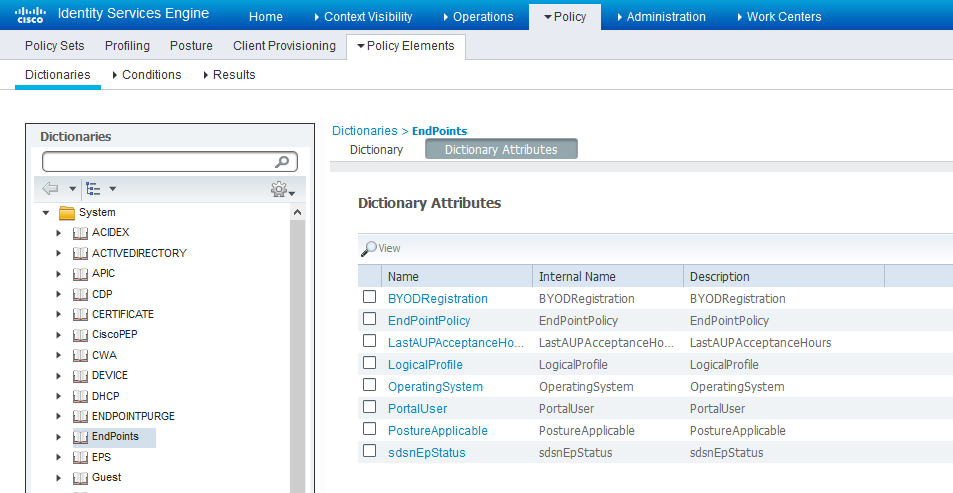
-
Navigate to Policy > Policy Elements > Conditions > Authorization > Simple Conditions. Add there authorization simple conditions using the sdsnEpStatus attribute you created.
In the screen below,, there are three conditions created using sdsnEpStatus attribute. The condition names do not need to be the same as in the screen here, but the expressions must be matched. These conditions will be used in Policy Sets to handle the threat remediation for managed endpoints as described later in the Policy Sets setting section. Only the sdsnEpStatus-blocked and sdsnEpStatus-quarantine conditions will be used there. sdsnEpStatus-healthy is created for fulfillment purpose and can be ignored for now.
Figure 10: Cisco ISE: Configure Simple Conditions, Match Expression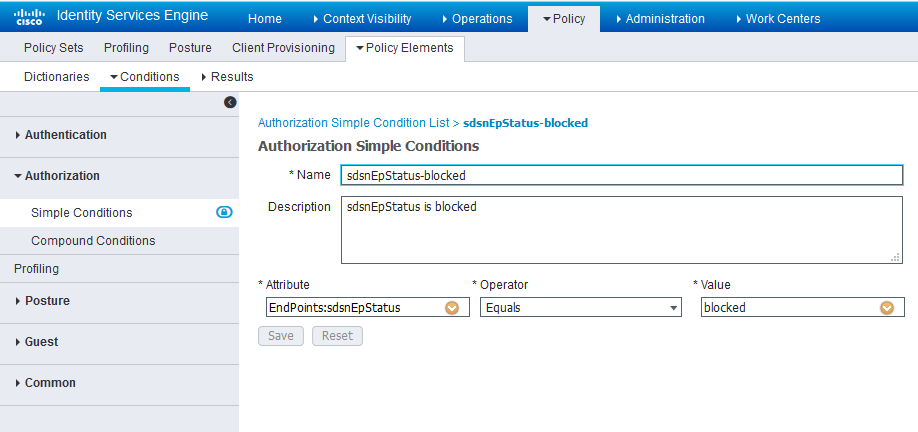 Figure 11: Cisco ISE: Configure Simple Conditions, Match Expression
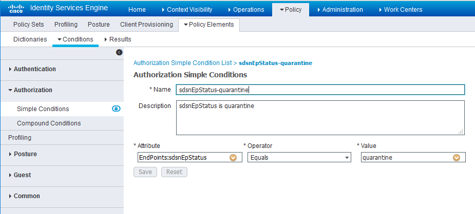
Configure permission/authorization profiles.
You can create the authorization profiles corresponding to “block” and “quarantine” actions as fits your needs. In the sample configuration provided here, the block action will result as total denial access to the network, and the quarantine profile will move the endpoint to another designated VLAN.
-
Navigate to From Policy > Policy Elements > Results > Authorization > Authorization Profiles.
Refer to the figures below for sample configurations.
Figure 12: Cisco ISE: Configure Authorization Profiles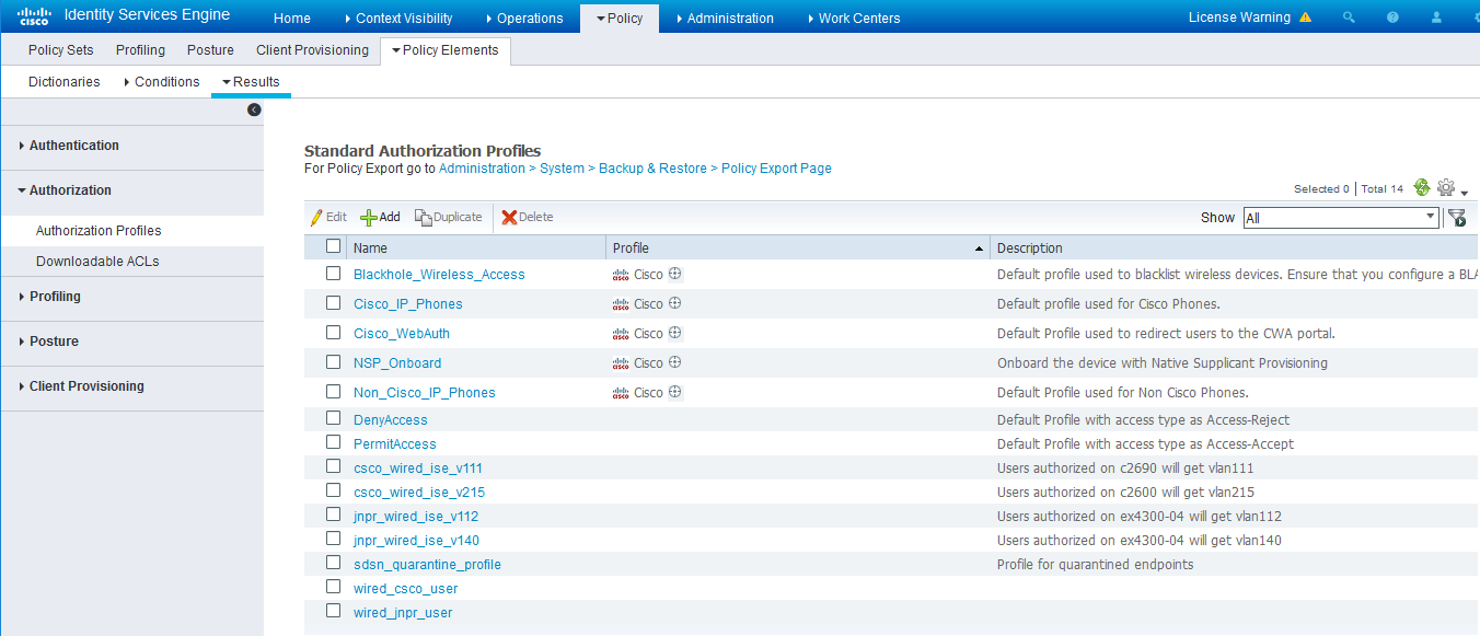 Figure 13: Cisco ISE: Configure Authorization Profiles
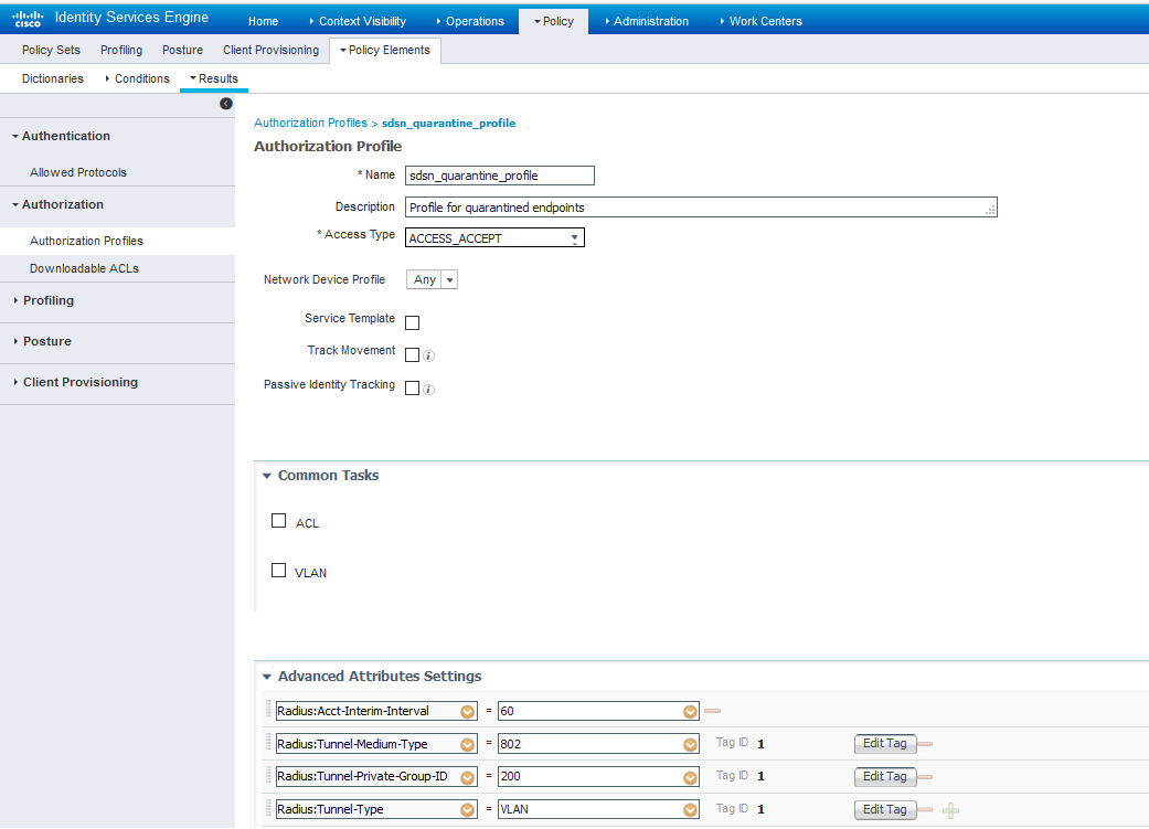 Note:
Note:For blocking a host, the default ‘DenyAccess’ profile is used.
Set the authorization policy:
-
Create two rules as Local Exceptions, applying the conditions and authorization/permission profiles we created in the previous step. Names may be different, but these two rules must be at the top of the Exception list.
Refer to the figure below for a sample configuration.
Figure 14: Cisco ISE: Local Exception Rules, Example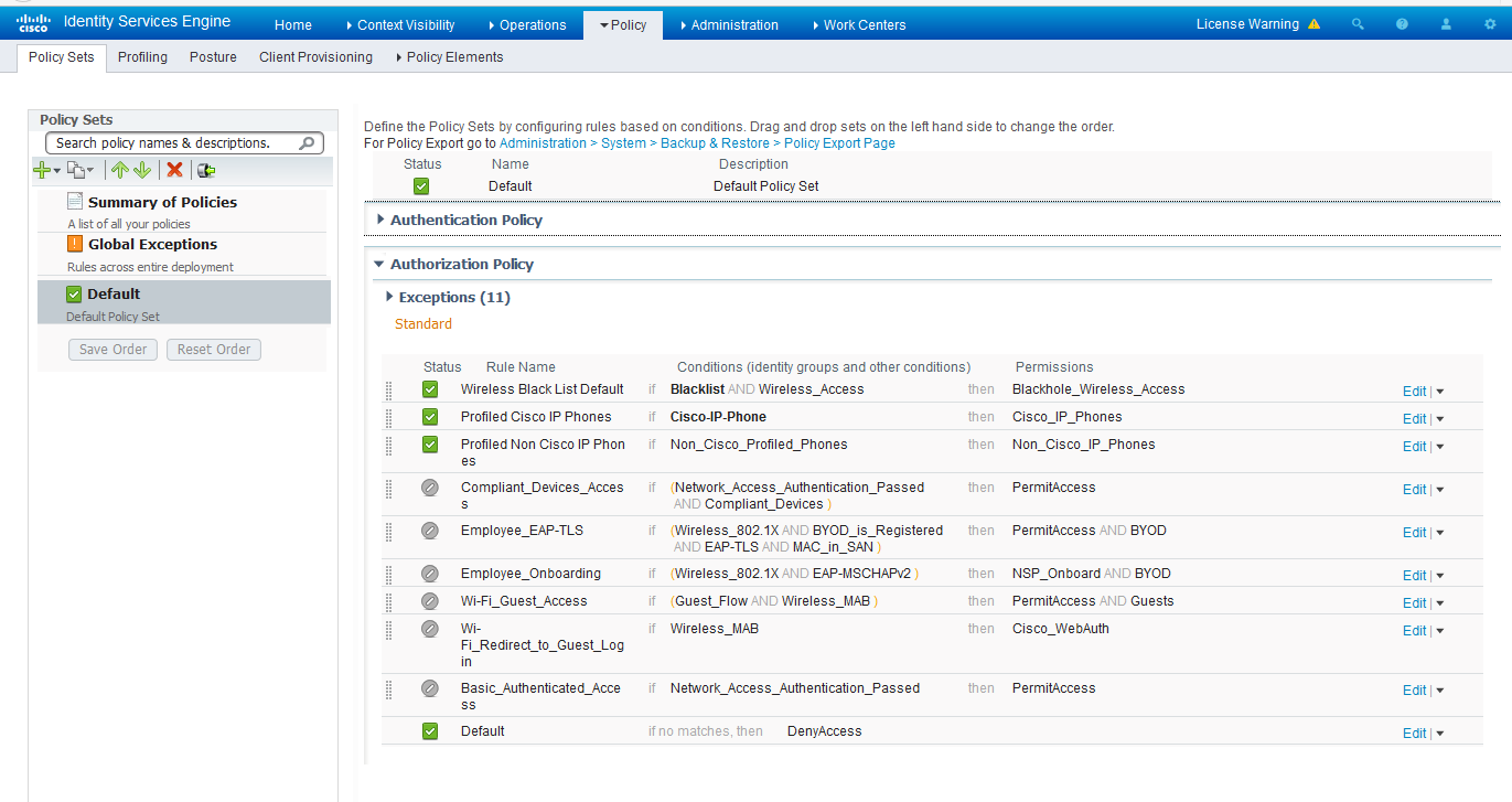 Note:
Note:Find this under Policy > Policy Sets > Authorization Policy.
-
Proceed to Creating a Policy Enforcer Connector for Third-Party Switches to finish the configuration with Policy Enforcer.