Understanding the Network Topology in Network Director
Junos Space Network Director provides features for monitoring and managing Juniper Networks EX Series Ethernet Switches, and QFX Series devices besides enabling connectivity visualization between discovered and managed devices such as routers and switches. Connectivity between devices and their association with their location provide the foundation for rendering topology in a complete manner.
As a network administrator, you must have a clear understanding of the various networking devices in your network, their physical locations, and how these devices are interconnected in your network. The network topology represents the interconnection between various devices in your network, which are managed by Network Director, based on their connectivity and association to their physical surroundings. The network topology provides a visual insight into the network, which is useful for debugging, troubleshooting, planning, and executing administrative actions.
Before you access the topological view of your network, you must:
Connect your Network Director system to the Internet before accessing Topology View in Network Director as this feature works only while the system is connected to the Internet.
Note:Ensure that Internet connection is available for both the Network Director and Network Director client systems.
Discover the devices managed by Network Director in your network. For details about discovering devices, see Discovering Devices in a Physical Network.
Note:You must specify the SNMP parameters during device discovery to have all the devices discovered and managed by Network Director available in Topology View. However, you can specify the SNMP parameters in the Refresh Topology task from the Topology View also.
Note:Ensure that you have enabled the LLDP, STP, or RSTP protocols on the devices as Network Director uses these protocols to determine the connectivity of devices with their neighbors in the network. LLDP and RSTP protocols are enabled by default on all EX Series switches and QFX Series devices.
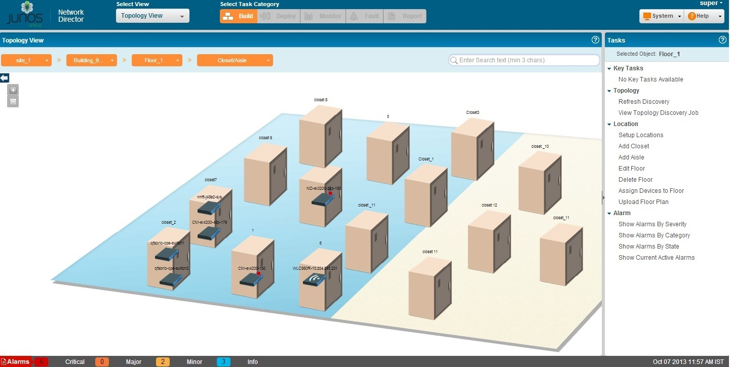
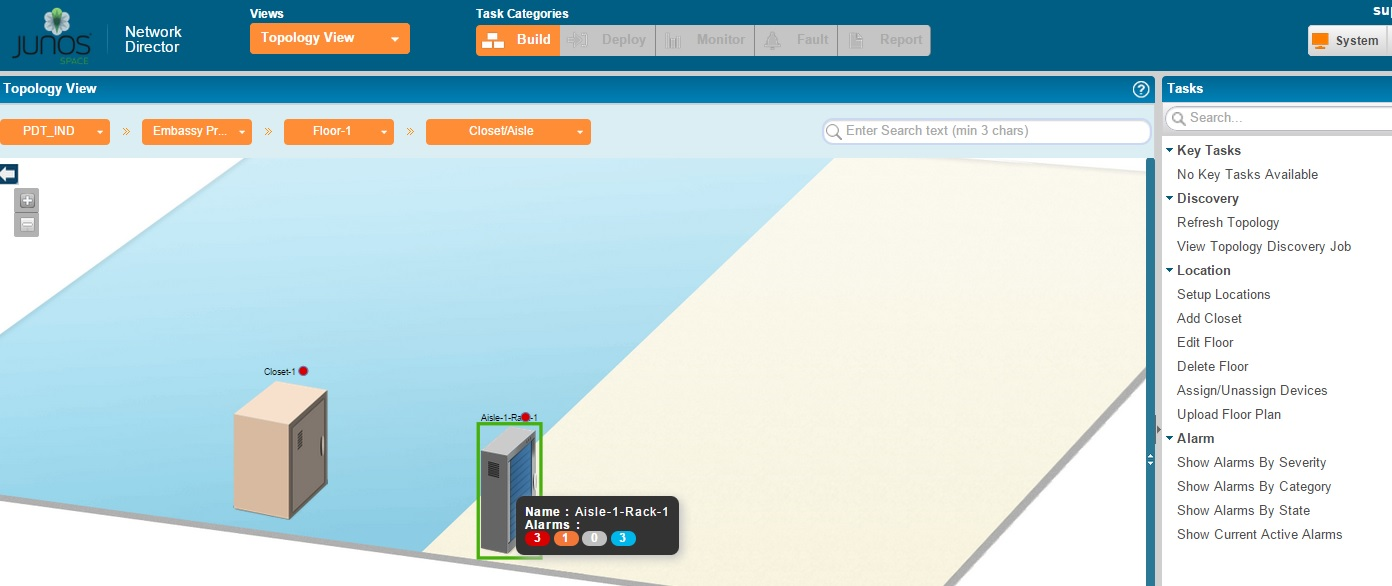
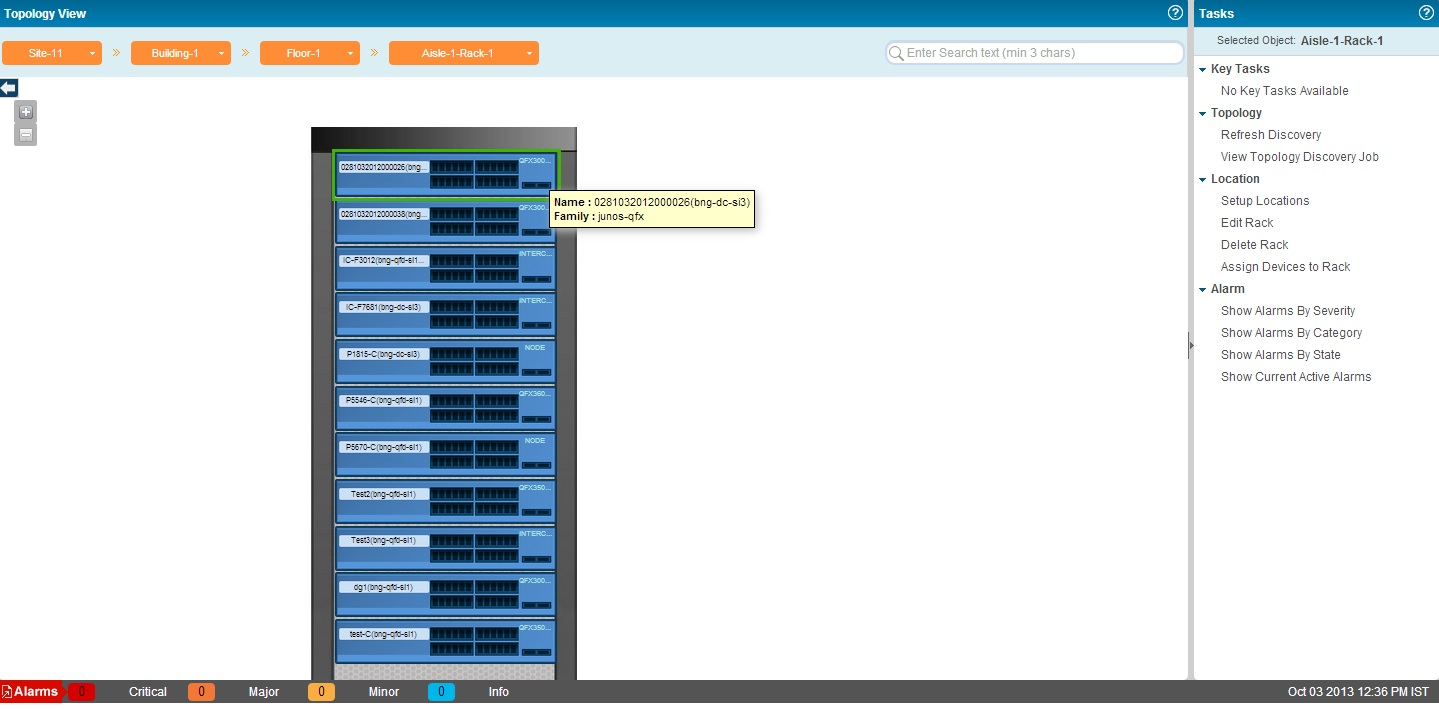
Set up the physical location of the devices in your network based on the geographical location of the devices. Some examples of location nodes are: sites, buildings, floors, closets, and aisles. You can set up one location node within another location node as in buildings within a site or floors within a building. You can then assign the network devices based on their location in buildings, floors, outdoor areas, closets, and racks. Apart from using the Location Management tasks in the Location View, you can set up the location details of the network devices managed by Network Director by using the Setup Locations task from the Task menu in the Topology View. For details, see Setting Up the Location View. The device-to-topology-group location relationship is established when a device is placed at a specific location on a topology map.
Network topology enables you to view all the discovered devices in your network, overlaid on a map where the devices are located across sites, buildings, floors, outdoor area, closets, and racks along with their physical interconnection with other devices in your network. Topology also provides visualization around physical connectivity between various discovered interconnected devices.
You can use the Topology View to zoom in or zoom out of a site to a building and a building to a site. In the Topology View, you can also double-click a node such site, buildings, and so on to navigate to the next node. You can also see the connectivity between a device and its immediate neighbors, alarms details, and so on. Network Director also enables you to assign devices to buildings, floors, closets, and outdoor areas on the map.
Network topology also provides visualization around physical connectivity between various discovered interconnected devices. You can upload a floor plan at the floor level or a map at the outdoor area if you already have the floor plan or map available. You can then move the nodes in the Topology View page based on the floor plan.
The topology display is created by layering the device images on top of the imported floor plan images as shown in Figure 1 and Figure 2.