ON THIS PAGE
Example: Small Branch Deployment Using NFX150 NextGen uCPE
This example shows how to configure 802.1X authentication on the LAN ports of the NFX150 device and how to onboard an Ubuntu-based VNF. The RADIUS server for authentication is based on FreeRADIUS.
The configuration of the FreeRADIUS server is beyond the scope of this document.
Requirements
One NFX150 device.
Note:This example is tested using a NFX150-S1 device. This example also supports the use of NFX150-C-S1, NFX150-C-S1-AE, NFX150-C-S1-AA, NFX150-C-S1E-AE, NFX150-C-S1E-AA, NFX150-S1, or NFX150-S1E devices.
Junos OS Release 20.1R1 or later.
Ubuntu 20.04 operating system.
FreeRADIUS version 3.
The workstation used in this example to generate the iso and the qcow2 files is based on Ubuntu 20.04
operating system. If you are using a workstation other than Ubuntu,
such as Windows, then the steps to generate the iso and
the qcow2 files might differ slightly.
Overview
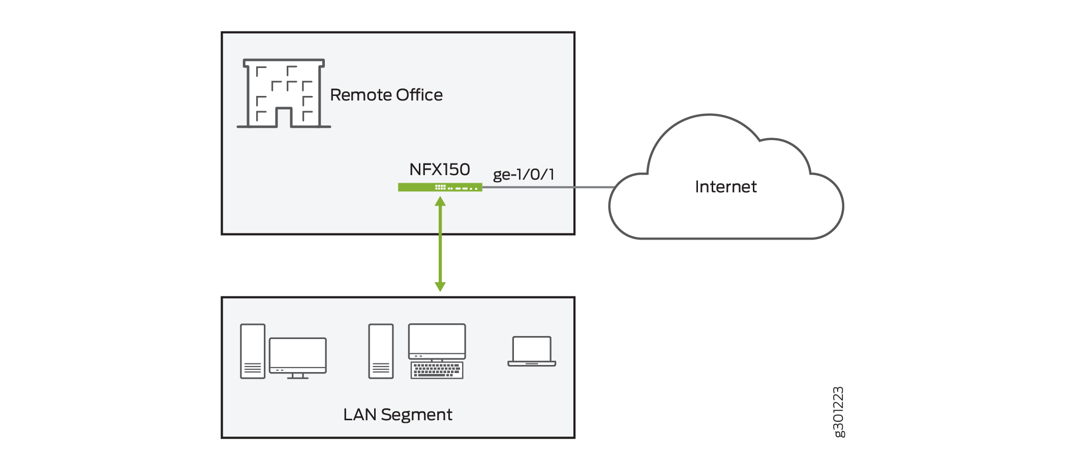
In this example, we set up a branch NFX150 uCPE to provide wired Internet and Intranet access to employees on site. The broadband Internet access is through an Ethernet link. An Ubuntu 20.04-based VNF is onboarded on the NFX150 device. FreeRADIUS RADIUS server provides 802.1X authentication to the LAN ports of the NFX150 device.
Topology
Figure 1 shows a remote branch office, which is connected to the Internet using NFX150. The 802.1X authentication is configured on the LAN ports of the NFX150 device to provide Internet and Intranet access.
The service chaining of the VNF, as well as the interface configuration details on the NFX150 are depicted in Figure 2:
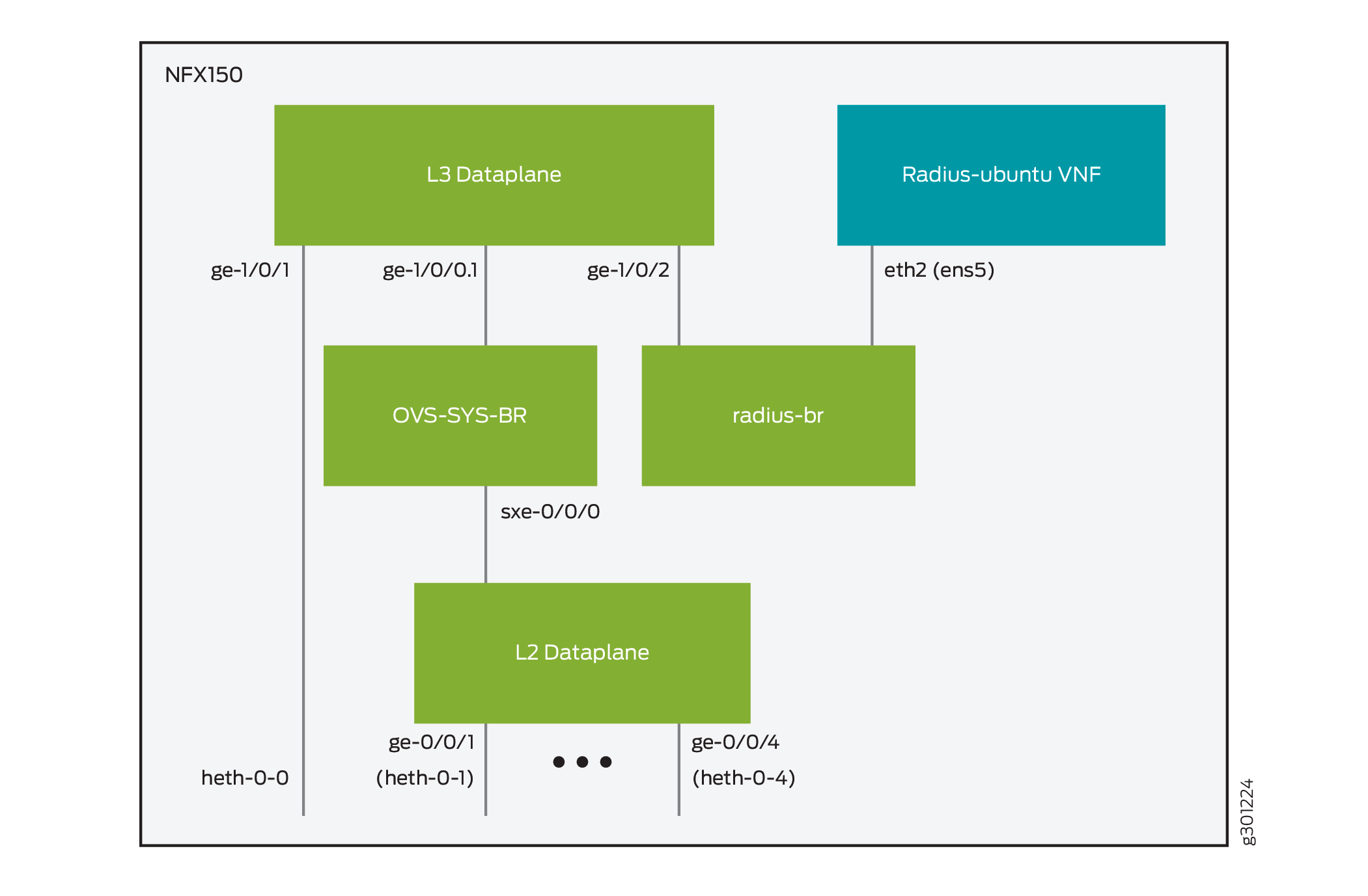
In the topology Figure 2:
Broadband Internet link is connected to interface ge-1/0/1. The interface is directly connected to the physical interface heth-0-0.
1 Gbps host Ethernet links (heth-0-1 through heth-0-4) of the NFX150 device are connected to the default VLAN 1.
Default VLAN 1 is propagated further to interface sxe-0/0/0 and is configured on the interface ge-1/0/0 as unit 1. The sub-interface is used for the DHCP server to provide network address configuration to the devices connected to the front ports of the NFX150 device. The Layer 2 interfaces of ports heth-0-1 through heth-0-4 are ge-0/0/1 through ge-0/0/4, respectively.
Interfaces ge-1/0/2 and eth2 are connected to the custom bridge radius-br. The interface eth2 of the VNF is recognized by the Ubuntu operating system as ens5.
In this example, there are two security zones (untrust and trust) configured on the NFX150. The separation of the interfaces into security zones enables the separation of traffic and mitigates the risks the corporate Intranet is exposed to. Security zones also serve as a vehicle to achieve clear and simplified implementation of security policies. The untrust zone hosts the interfaces that have access to the Internet. The internal interfaces in the corporate Intranet are in trust zone. Specifically, interface ge-1/0/1 is in untrust zone, while rest of the LAN interfaces are in trust zone. Figure 3 and the following table show the interfaces, security zones, and security policy configurations:

From Zone |
To Zone |
Security Policy Behavior to Allow Traffic |
|---|---|---|
trust |
trust |
No |
untrust |
untrust |
No |
trust |
untrust |
Yes |
untrust |
trust |
Trust-initiated only. Allow the traffic initiated in the trust zone and the return traffic. |
Table 2 summarizes the VLAN information and the IP address information for the interfaces.
Interface |
VLAN ID |
IP Address |
Network Mask |
|---|---|---|---|
ge-1/0/1 |
— |
DHCP |
— |
ge-1/0/0.1 |
default Note:
The default VLAN has VLAN ID value as 1. |
192.168.2.1 |
255.255.255.0 |
ge-1/0/2 |
radius-br |
10.10.10.2 |
255.255.255.0 |
Configuration
To deploy branch office with virtualized 802.1X authentication with NFX150 NextGen universal CPE device, perform these tasks:
- Stage Ubuntu 20.04-based VNF
- Fine-tune the NFX Operation Mode
- Configure VNF and Set Up Custom OVS Bridge
- Map Physical Ports to Layer 2 and Layer 3 Interfaces
- Configure Zone-based Firewall and NAT
- Configure DHCP Server for LAN Users
- Configure 802.1X Authentication
Stage Ubuntu 20.04-based VNF
Step-by-Step Procedure
The following steps describe how to stage Ubuntu 20.04-based VNF:
Download the cloud-based ubuntu-20.04-server-cloudimg-amd64.vmdk image file of Ubuntu 20.04 from the official Ubuntu website on the workstation.
user@workstation$wget -nc https://cloud-images.ubuntu.com/releases/focal/release/ubuntu-20.04-server-cloudimg-amd64.vmdk
Convert the ubuntu-20.04-server-cloudimg-amd64.vmdk image file to qcow2 file format.
user@workstation$qemu-img convert -f vmdk -O qcow2 ubuntu-20.04-server-cloudimg-amd64.vmdk ubuntu-20.04-server-cloudimg-amd64.qcow2
Create a copy of the qcow2 file for your VNF. The name of the VNF is radius-ubuntu and the name of the qcow2 file is radius-ubuntu.qcow2.
user@workstation$cp ubuntu-20.04-server-cloudimg-amd64.qcow2 radius-ubuntu.qcow2
Open your favorite text editor on the workstation and create the cloud-init configuration file for the VNF. The cloud-init configuration contains basic information such as the line #cloud-config, password for the default user (ubuntu), configuration stanzas that do not allow password expiration for the user, and the configuration to allow the password authentication to the VNF. By default, the cloud-based Ubuntu image allows only the SSH key-based authentication. The hostname for the VNF is also defined in the file. The VNF is named radius-ubuntu. In this example, the cloud-init configuration file for the VNF is named radius-ubuntu.txt.
#cloud-config
password: $ABC123
chpasswd: { expire: False }
ssh_pwauth: True
hostname: radius-ubuntu
Create an iso file from the radius-ubuntu.txt config-init file as radius-ubuntu.iso. The radius-ubuntu.iso file is stored in the same directory.
user@workstation$cloud-localds ./radius-ubuntu.iso radius-ubuntu.txt
Copy the radius-ubuntu.qcow2 and the radius-ubuntu.iso files to the
/var/publicdirectory on the NFX150 device. Make sure to use the correct credentials if you want to use the following method to copy the files to the NFX150 uCPE. For example, root user’s credentials are used here to copy the files to the NFX150 device.user@workstation$scp radius-ubuntu.iso root@nfx-150-s1:/var/public/ user@workstation$scp radius-ubuntu.qcow2 root@nfx-150-s1:/var/public/
Fine-tune the NFX Operation Mode
Step-by-Step Procedure
The following steps describe how to fine-tune the NFX mode of operation:
Set the NFX in compute mode. Compute mode provides maximum resources for third-party VNFs. The NFX150 device reboots after setting the NFX in compute mode.
user@host>request vmhost mode compute
Enable the usage of hugepages on the device. The hugepages are memory pages that do not get swapped out of memory. In this example, there are four hugepages created that will be used for the VNF.
[edit]
user@host>set system memory hugepages page-size 1024 count 4
user@host>commit and-quit
Reboot the NFX150 device for the hugepages to take effect.
user@host>request vmhost reboot
Configure VNF and Set Up Custom OVS Bridge
Step-by-Step Procedure
The following steps describe how to configure the VNF and set up the custom OVS bridge. The custom OVS bridge acts as the NFV backplane to which the VNFs and FPCs connect. Additionally, you can create custom OVS bridges to isolate connectivity between different VNFs.
Create the VNF and set the name radius-ubuntu. You need to set the path to the image (
/var/public/radius-ubuntu.qcow2) for the VNF.[edit] user@host#set virtual-network-functions radius-ubuntu image /var/public/radius-ubuntu.qcow2 user@host#set virtual-network-functions radius-ubuntu image image-type qcow2
Configure the VNF to have two CPUs, enable the hardware virtualization for the CPUs, and dedicate 4 GB of memory for the VNF. It is mandatory to configure CPUs and allocate memory for the VNF. For Ubuntu 20.04 cloud image, it is recommended to configure a minimum of 1 CPU and at least 1 GB of memory.
[edit]
user@host#set virtual-network-functions radius-ubuntu virtual-cpu count 2
user@host#set virtual-network-functions radius-ubuntu virtual-cpu features hardware-virtualization
user@host#set virtual-network-functions radius-ubuntu memory size 4194304
user@host#set virtual-network-functions radius-ubuntu memory features hugepages
Map the eth2 interface with the custom bridge radius-br.
[edit]
user@host#set virtual-network-functions radius-ubuntu interfaces eth2 mapping vlan mode access
user@host#set virtual-network-functions radius-ubuntu interfaces eth2 mapping vlan members radius-br
Mount the cloud-init image radius-ubuntu.iso file as CD-ROM drive.
[edit]
user@host#set virtual-network-functions radius-ubuntu storage vdb type cdrom source file /var/public/radius-ubuntu.iso
Create the custom OVS bridge radius-br and configure the interface ge-1/0/2 to it.
[edit]
user@host#set vmhost vlans radius-br vlan-id none
user@host#set vmhost virtualization-options interfaces ge-1/0/2 mapping vlan radius-br
Map Physical Ports to Layer 2 and Layer 3 Interfaces
Step-by-Step Procedure
The following steps describe how to map the physical ports to the Layer 2 and Layer 3 interfaces. The physical interfaces represent the physical ports on the NFX150 chassis and expansion module. The physical ports on the front panel of the NFX150 device can be mapped to Layer 2 or Layer 3 interfaces, or VNFs.
Map the physical port heth-0-0 to the Layer 3 (FPC1) interface.
[edit]
user@host#set vmhost virtualization-options interfaces ge-1/0/1 mapping interface heth-0-0
Map the physical ports heth-0-1 through heth-0-4 to the Layer 3 (FPC1) interfaces.
[edit]
user@host#set vmhost virtualization-options interfaces ge-0/0/1 mapping interface heth-0-1
user@host#set vmhost virtualization-options interfaces ge-0/0/2 mapping interface heth-0-2
user@host#set vmhost virtualization-options interfaces ge-0/0/3 mapping interface heth-0-3
user@host#set vmhost virtualization-options interfaces ge-0/0/4 mapping interface heth-0-4
Add the interfaces ge-0/0/1 through ge-0/0/4 and interface sxe-0/0/0 as members of the default VLAN.
[edit]
user@host#set interfaces ge-0/0/1 unit 0 family ethernet-switching vlan members default
user@host#set interfaces ge-0/0/2 unit 0 family ethernet-switching vlan members default
user@host#set interfaces ge-0/0/3 unit 0 family ethernet-switching vlan members default
user@host#set interfaces ge-0/0/4 unit 0 family ethernet-switching vlan members default
user@host#set interfaces sxe-0/0/0 unit 0 family ethernet-switching vlan members default
Configure Zone-based Firewall and NAT
Step-by-Step Procedure
The following steps describe how to configure zone-based firewall filters and NAT:
Create a security zone, trust, and assign Layer 3 interfaces (ge-1/0/0.0 and ge-1/0/2) to that zone. The ge-1/0/0.0 Layer 3 interface act as a DHCP server for the LAN connected device and the radius-br interface. The ge-1/0/0.0 interface is the default interface and it is part of the default configuration of the NFX150 device.
[edit]
user@host#set security zones security-zone trust host-inbound-traffic system-services all
user@host#set security zones security-zone trust host-inbound-traffic protocols all
user@host#set security zones security-zone trust interfaces ge-1/0/0.1
user@host#set security zones security-zone trust interfaces ge-1/0/2.0
Create a security zone, untrust, and assign the Layer 3 interface ge-1/0/1.0. You can configure the system services and protocols as per your setup.
[edit]
user@host#set security zones security-zone untrust host-inbound-traffic system-services all
user@host#set security zones security-zone untrust host-inbound-traffic protocols all
user@host#set security zones security-zone untrust interfaces ge-1/0/1.0
Note:In a production environment you should restrict the protocols and services that you only want to be allowed in the network.
Create security policies to allow the traffic within the security zone trust.
[edit]
user@host#set security policies from-zone trust to-zone trust policy default-permit match source-address any
user@host#set security policies from-zone trust to-zone trust policy default-permit match destination-address any
user@host#set security policies from-zone trust to-zone trust policy default-permit match application any
user@host#set security policies from-zone trust to-zone trust policy default-permit then permit
Create security policies to allow traffic from security zone trust to security zone untrust.
[edit]
user@host#set security policies from-zone trust to-zone untrust policy trust-to-untrust match source-address any
user@host#set security policies from-zone trust to-zone untrust policy trust-to-untrust match destination-address any
user@host#set security policies from-zone trust to-zone untrust policy trust-to-untrust match application any
user@host#set security policies from-zone trust to-zone untrust policy trust-to-untrust then permit
Create source NAT rule to NAT traffic from zone trust into zone untrust.
[edit]
user@host#set security nat source rule-set trust-to-untrust from zone trust
user@host#set security nat source rule-set trust-to-untrust to zone untrust
user@host#set security nat source rule-set trust-to-untrust rule source-nat-rule match source-address 0.0.0.0/0
user@host#set security nat source rule-set trust-to-untrust rule source-nat-rule then source-nat interface
Configure DHCP Server for LAN Users
Step-by-Step Procedure
The following steps describe how to configure the DHCP server:
Create a sub-interface for ge-1/0/0 in the default VLAN because an interface is required for the DHCP server.
[edit]
user@host#set interfaces ge-1/0/0 vlan-tagging
user@host#set interfaces ge-1/0/0 unit 0 vlan-id 1
user@host#set interfaces ge-1/0/0 unit 0 family inet address 192.168.2.1/24
Create the DHCP address pool and set the interface as ge-1/0/0.1. The following DHCP address pool parameters are used in this example:
Name of the DHCP address pool is jdhcp-group.
User-assigned IP addresses range from 192.168.2.2 to 192.168.2.254.
Gateway IP address is 192.168.2.1.
DNS server address is set to 8.8.8.8.
[edit]
user@host#set access address-assignment pool jdhcp-group family inet network 192.168.2.0/24
user@host#set access address-assignment pool jdhcp-group family inet range junosRange low 192.168.2.2
user@host#set access address-assignment pool jdhcp-group family inet range junosRange high 192.168.2.254
user@host#set access address-assignment pool jdhcp-group family inet dhcp-attributes router 192.168.2.1
user@host#set access address-assignment pool jdhcp-group family inet dhcp-attributes name-server 8.8.8.8
user@host#set access address-assignment pool jdhcp-group family inet dhcp-attributes propagate-settings ge-1/0/0.0
Configure 802.1X Authentication
Step-by-Step Procedure
The following steps describe how to configure 802.1X authentication.
The configuration of network interfaces and the RADIUS server on the Ubuntu VNF is beyond the scope of this document.
Configure the RADIUS server, which is running on the VNF. The following RADIUS server parameters are used in this example:
IP address of the RADIUS server is 10.10.10.2. This is the IP address of eth2 and ens5 of the radius-ubuntu VNF.
Secret password used by the NFX to communicate with the RADIUS server is
$ABC123.
[edit]
user@host#set access radius-server 10.10.10.2 port 1812
user@host#set access radius-server 10.10.10.2 secret $ABC123
Add the RADIUS server to a profile and allow RADIUS authentication using that profile. The profile name used in this example is vnf-radius.
[edit]
user@host#set access profile vnf-radius radius authentication-server 10.10.10.2
user@host#set access profile vnf-radius authentication-order radius
Configure the profile vnf-radius as the 802.1X authenticator. The 802.1X authenticator validates the user-entered credentials with the RADIUS server and acts accordingly.
[edit]
user@host#set protocols dot1x authenticator authentication-profile-name vnf-radius
Configure supplicants (users) to be authenticated on the interface ge-0/0/1.0 and request reauthentication every 90 minutes (5400 seconds). You can allow multiple supplicants to be authenticated as shown in this example.
[edit]
user@host#set protocols dot1x authenticator authentication-profile-name vnf-radius
user@host#set protocols dot1x authenticator interface ge-0/0/1.0 supplicant multiple
user@host#set protocols dot1x authenticator interface ge-0/0/1.0 reauthentication 5400
Set the timeout timers for both the supplicant authentication and the RADIUS server, for example 60 seconds.
[edit]
user@host#set protocols dot1x authenticator interface ge-0/0/1.0 supplicant-timeout 60
user@host#set protocols dot1x authenticator interface ge-0/0/1.0 server-timeout 60
Configure the behavior for the port. In case the RADIUS server is unreachable, you can configure the authentication behavior for the port to specifically use the available cache. In this case, the supplicants authenticated already can continue to use the port and other supplicants will not be allowed.
[edit]
user@host#set protocols dot1x authenticator interface ge-0/0/1.0 server-fail use-cache
Commit the configuration.
[edit]
user@host#commit and-quit
Repeat the steps 4 through 6 for configuring authentication on the interfaces ge-0/0/2.0 through ge-0/0/4.0.
Verification
To confirm that the configuration is working properly, perform the following tasks:
- Verifying the VNF is Up and Running
- Verifying the Resource Utilization for the VNF
- Verifying the Interfaces on the Custom Bridge
Verifying the VNF is Up and Running
Purpose
Verify that the VNF was spun successfully.
Action
From operational mode, enter the show virtual-network-functions
radius-ubuntu detail command.
user@host> show virtual-network-functions radius-ubuntu detail

Virtual Network Function Information
------------------------------------

Id:                 2
Name:               radius-ubuntu
UUID:               2686abc4-0f66-4574-a5de-18a3bbd09a94
State:              Running
Liveliness:         alive
IP Address:         192.0.2.100
VCPUs:              2
Maximum Memory:     4194304 KiB
Used Memory:        52172 KiB
Used 1G Hugepages:  4
Used 2M Hugepages:  0
Error:              None
Meaning
The output shows the details of radius-ubuntu VNF such as state, liveliness, errors, as well as memory usage.
Verifying the Resource Utilization for the VNF
Purpose
Verify what resources the VNF system is currently using such as CPU time, memory usage, and also the MAC address information of the interface.
Action
From operational mode, enter the show system visibility
vnf radius-ubuntu command.
user@host> show system visibility vnf radius-ubuntu

VNF Memory Usage
--------------------------------------------------------------------------------------------------------------------
Name                                   Maximum Memory (KiB)  Used Memory (KiB)  Used 1G Hugepages  Used 2M Hugepages
-------------------------------------- --------------------- ------------------ ------------------ -----------------
radius-ubuntu                          4194304               52172              4                  0

VNF CPU Statistics (Time in ms)
-----------------------------------------------------------------------------------
Name                                   CPU Time           System Time  User Time
-------------------------------------- ------------------ ------------ ------------
radius-ubuntu                          164985             59820        4480

VNF MAC Addresses
-----------------------------------------------------------
VNF                                       MAC
----------------------------------------- -----------------
radius-ubuntu_ethdef0                     58:00:BB:AC:BC:5B
radius-ubuntu_ethdef1                     58:00:BB:AC:BC:5C
radius-ubuntu_eth2                        58:00:BB:AC:BC:5D

VNF Internal IP Addresses
---------------------------------------------------------
VNF                                       IP
----------------------------------------- ---------------
radius-ubuntu                             192.0.2.100

VNF Interfaces
--------------------------------------------------------------------------------------------------------
VNF                  Interface Type      Source       Model      MAC               IPv4-address
-------------------- --------- --------- ------------ ---------- ----------------- ---------------------
radius-ubuntu        vnet4     network   default      virtio     58:00:bb:ac:bc:5b --
radius-ubuntu        vnet5     bridge    eth0br       virtio     58:00:bb:ac:bc:5c --
radius-ubuntu        radius-ubuntu_eth2 vhostuser --  virtio     58:00:bb:ac:bc:5d --

VNF Disk Information
---------------------------------------------------------------------------------------------------------
Meaning
The output shows the system details of radius-ubuntu VNF such as memory usage, CPU time, MAC addresses, and IP addresses.
Verifying the Interfaces on the Custom Bridge
Purpose
Verify the status of the interfaces on the custom bridge.
Action
From operational mode, enter the show vmhost network
nfv-back-plane command.
user@host> show vmhost network nfv-back-plane

Network Name : radius-br

   Interface : radius-br
   Type : internal, Link type : Full-Duplex, MAC : ce:74:aa:85:0f:4d
   MTU : [], Link State :down, Admin State : down
   Native Vlan ID : None, Vlan mode : Access, Vlan Members : None
   IPV4 : None, Netmask : None
   IPV6 : None, IPV6 netmask : None
       Rx-packets :       0
       Rx-drops   :       0
       Rx-errors  :       0
       Tx-packets :       43
       Tx-drops   :       43
       Tx-errors  :       0

   Interface : l3_h_ge_1_0_2
   Type : dpdkvhostuser, Link type : Full-Duplex, MAC : 00:00:00:00:00:00
   MTU : [], Link State :up, Admin State : up
   Native Vlan ID : None, Vlan mode : Access, Vlan Members : None
   IPV4 : None, Netmask : None
   IPV6 : None, IPV6 netmask : None
       Rx-packets :       32
       Rx-drops   :       0
       Rx-errors  :       0
       Tx-packets :       59
       Tx-drops   :       0
       Tx-errors  :       0

   Interface : radius-ubuntu_eth2
   Type : dpdkvhostuser, Link type : Full-Duplex, MAC : 00:00:00:00:00:00
   MTU : 1500, Link State :up, Admin State : up
   Native Vlan ID : None, Vlan mode : Access, Vlan Members : None
   IPV4 : None, Netmask : None
   IPV6 : None, IPV6 netmask : None
       Rx-packets :       59
       Rx-drops   :       0
       Rx-errors  :       0
       Tx-packets :       31
       Tx-drops   :       0
       Tx-errors  :       0
Meaning
In the output, you can see the interfaces l3_h_ge_1_0_2 and radius-ubuntu_eth2 are linked to ge-1/0/2 and eth2, respectively. The output also shows the link status details (admin and link state) of the interfaces and the number of packets received and the transmitted through the respective interfaces.