ZTIS Branch Designs
As previously mentioned, ZTIS removes traditional limitations and allows microsegmentation even in simple branch deployments without requiring an EVPN fabric. To get started, you only need a ZTIS-capable switch at the access layer. In the example below, a ZTIS-capable switch has also been added.
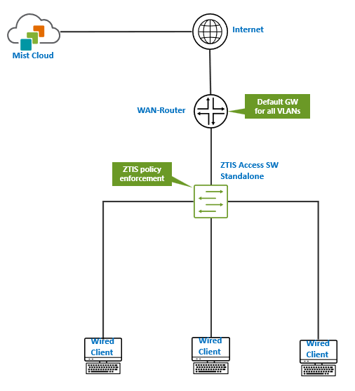
From a high-level perspective, the network topology remains unchanged in this scenario.
- The WAN router serves as the demarcation point between VLANs and acts as the default gateway for all of them.
- For a single SSID with an assigned VLAN for wireless clients, the network must ensure that this VLAN is available on every AP through the switch to support roaming.
- Wired clients may share the same VLAN as wireless clients, depending on design preference.
- If dynamic authentication using RADIUS is required, that service must be deployed somewhere in the network, though it is not shown here.
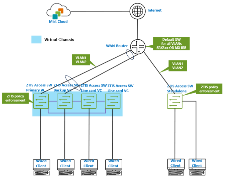
In the next scenario, a second access switch is added as a Virtual Chassis, and two or more VLANs are configured and shared via IRB interfaces on the WAN router.
In the next topology, we assume the deployment uses a Juniper Networks® SRX 1500 Series Firewall or above or a Juniper Networks® SSR Series Router. Since there are no IRB interfaces on the WAN router to interconnect the VLANs, a distribution/aggregation switch is placed between the WAN router and the access layer. This switch distributes the VLANs to the connected access switches or Virtual Chassis and provides a trunk uplink to the WAN router, allowing the VLANs to communicate upstream.
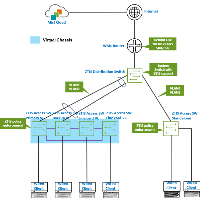
For ZTIS to function, the distribution switch does not need to support ZTIS. This capability is required only on access layer switches. If the upstream device is not detected as ZTIS-capable, which is determined through an additional LLDP extension, the access switches automatically use Layer 2 multicast to send ZTIS update and lookup messages. As a result, message flooding continues to work as expected.
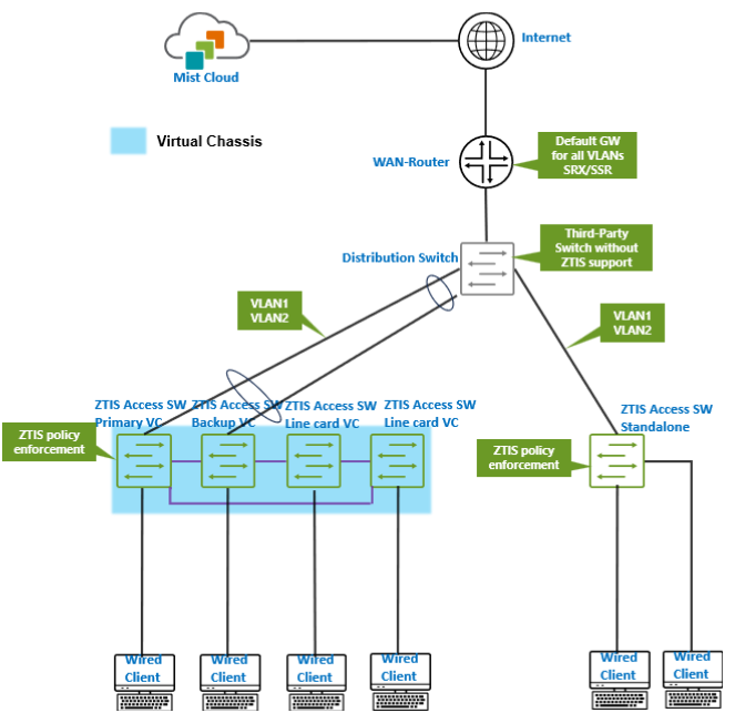
In this scenario, a third-party distribution switch requires no special configuration beyond the standard port setup and any optional LAG configuration.
In a branch deployment with only a few switches, it makes little difference whether the distribution switch supports ZTIS. However, LLDP-based detection of ZTIS-capable neighbors becomes important in campus fabric environments.
If you are low on physical devices, this allows you to build labs with virtual distribution switches (vJunos-switch) and WAN router VMs to explore branch scenarios like in the example below.
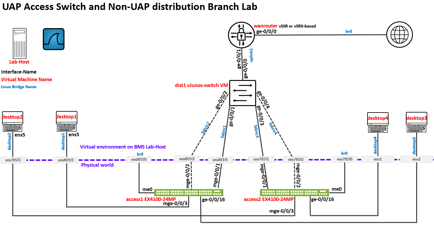
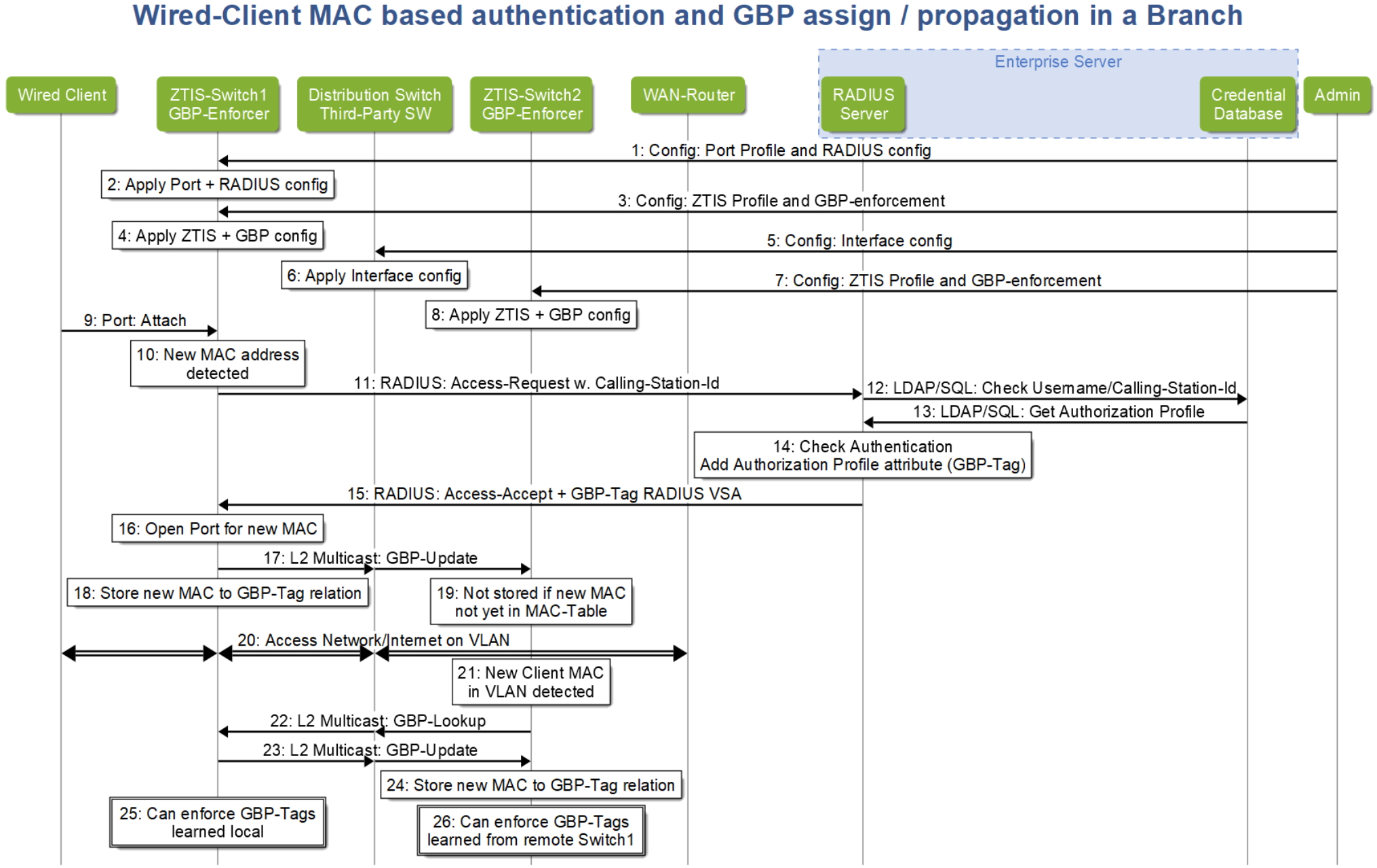
To better understand the last scenario, the following points outline the complete workflow for a wired client on the Access1 switch and a wired client (not shown) attached to the Access2 switch within the same VLAN:
- In Steps 3 through 8, the administrator, typically through the
Juniper Mist cloud, deploys the required configuration, including:
- ZTIS settings, such as the shared encryption key.
- GBP tag identification, whether assigned statically or dynamically.
- SGT enforcement on ZTIS-capable access switches.
- In Steps 9 through 16, a wired client authenticates using MAB. The process is very similar to the EAP authentication described earlier. When the final RADIUS access-accept message is received, it includes the dynamically assigned GBP tag, which is then learned by the ZTIS-capable access switch.
- In Steps 17 through 19, the access switch sends a Layer 2 multicast ZTIS update message to other devices in the network. At this stage, Access2 does not yet have the new MAC address in its table, so it does not act on the MAC-to-GBP mapping.
- In Steps 20 through 21, the wired client begins sending traffic and may attempt to communicate with devices in the same VLAN connected to Access2. As a result, Access2 learns the new MAC address but does not yet have an associated GBP tag for it.
- In Steps 22 through 24, Access2 sends a ZTIS lookup message into the network and receives the corresponding MAC-to-GBP mapping, which it stores in its local table.
- In Steps 25 through 26, both ZTIS-capable access switches now have the MAC-to-GBP mapping for the client and can enforce traffic policies as it enters the wired network.
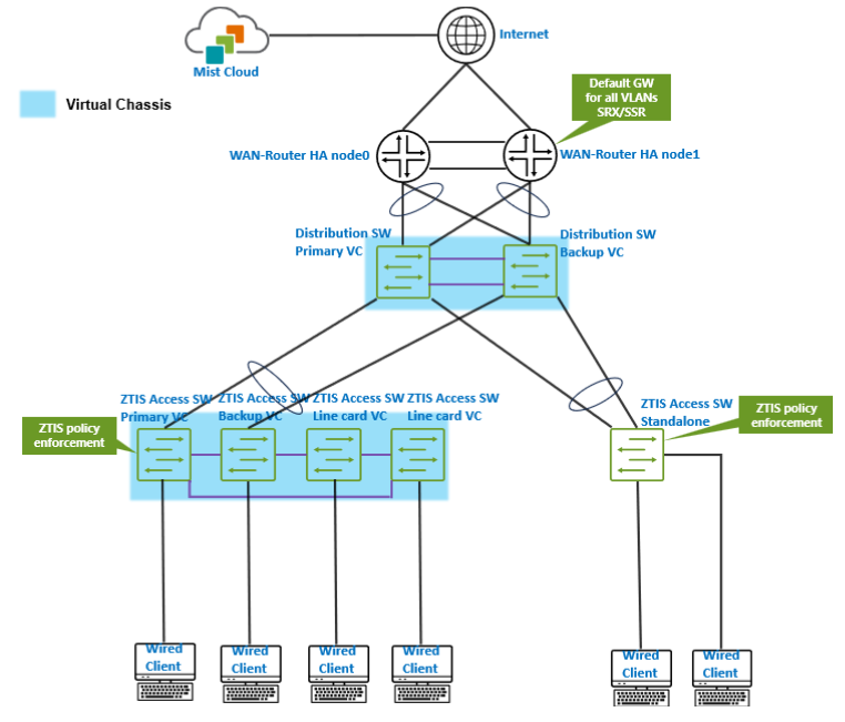
The branch topology shown in the previous scenario is designed to support larger scale and provide high availability on the WAN router side. When implementing high availability with a Juniper SSR or SRX-based WAN router using LAG for failover, the connected distribution switch must operate as a Juniper Virtual Chassis. This allows it to appear as a single logical switch to the WAN router across the LAG uplinks.
If standalone switches were used instead, forming a LAG toward the WAN router would not be possible because each switch would present a different chassis MAC address on the aggregated links. As noted earlier, the distribution Virtual Chassis does not need to support ZTIS, but it must support and operate using Juniper Virtual Chassis technology in this design.
We have not covered every possible variation of branch designs that support ZTIS here. However, you should now have a general sense of which devices are required to be ZTIS-capable, and which are not.
If your network design does not extend VLANs all the way to the WAN router as the default gateway, you can still use ZTIS and classify remote networks based on destination IP prefixes. Keep in mind, however, that these rules do not apply to traffic within the same network or VLAN.