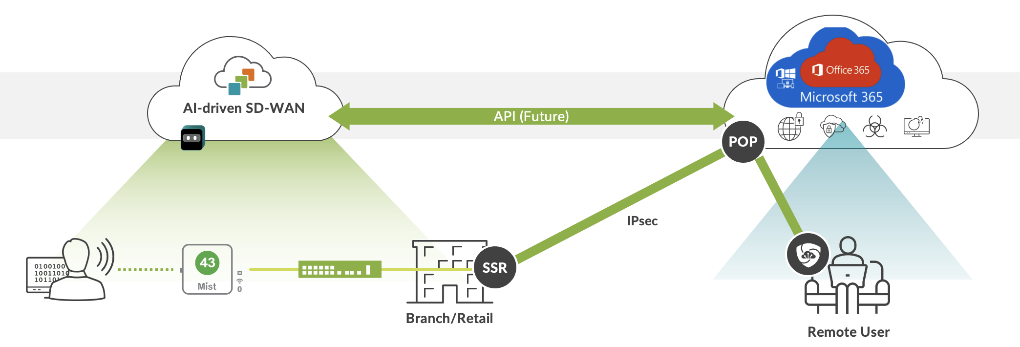
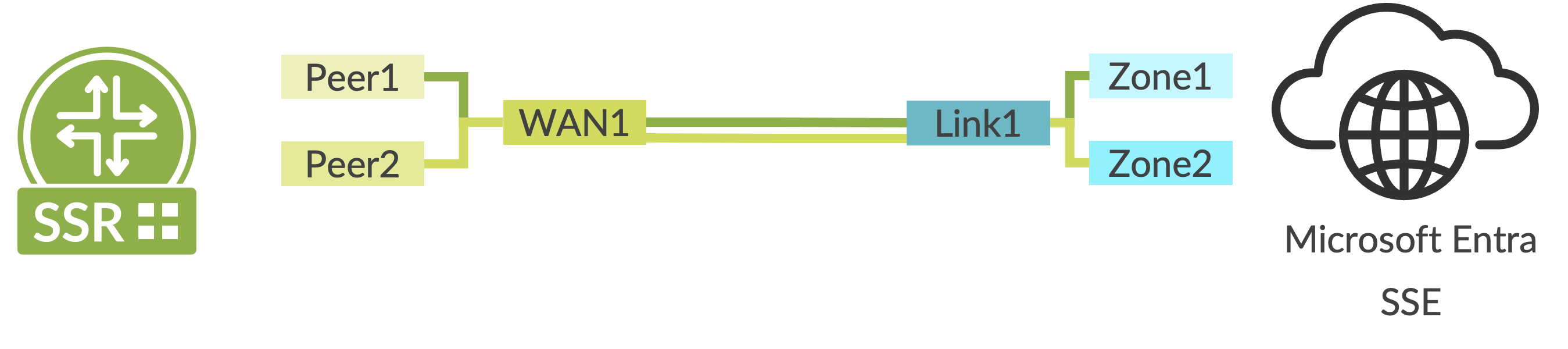
Use Case and Reference Architecture
This document enables the topology shown in Figure 1. An IPsec tunnel is configured between the Juniper AI-Driven SD-WAN device, also known as the Juniper Session Smart Router (SSR), and Microsoft’s SSE solution using the Secure Edge Connector within the WAN Edge template. Additionally, a BGP over IPsec connection is configured to dynamically learn routing destinations from Microsoft’s SSE solution. When used for Microsoft 365 access, Microsoft’s SSE solution-advertised addresses are used to determine the traffic sent to the service rather than the WAN Edge-based application dictionary.
Configuration Workflow
The sequence of tasks in this configuration example:
- Create and deploy a basic branch template for device connectivity. Creation of the basic template is out of scope of this guide, but the WAN Edge template might be stand-alone or SD-WAN with security enabled.
- Configure a remote network within the Microsoft Entra portal. This defines the IPsec tunnel characteristics and define routing endpoints for reachability.
- Configure a Secure Edge Connector in the device template. This creates a custom IPsec tunnel to Microsoft’s SSE solution and defines encryption parameters.
- Configure a BGP peer for Microsoft’s SSE solution service to learn Microsoft 365 destinations dynamically.
- Configure an application to allow traffic to be steered toward the IPsec tunnel. This application will be used in application policy to allow client networks to access the BGP learned routes.
- Configure an application policy with a network and application, but no traffic steering policy to indicate to the WAN Edge that the routing table should be used for learned destinations.
Configuration Planning
Prior to configuration, the following information must be available for each site:
- The public address of the WAN links that are used to reach Microsoft’s SSE solution service. At this time, only static WAN addresses might be used to reach the service.
- One or two /29 address ranges that are available for BGP peering between the WAN Edge loopback and Microsoft’s SSE solution. When zone redundancy is desired, two address ranges are required.
- A BGP AS for use by Microsoft’s SSE solution. This might be in the private AS range unused elsewhere in the enterprise network.
- Networks and users that are granted access to Microsoft’s SSE solution.
- Bandwidth desired for each site. This is used in remote network configuration within the Microsoft Entra portal.
- Desired redundancy model for each site. Options include single/dual WAN for the WAN Edge and single/dual Zone for Microsoft’s SSE solution. The single/dual WAN configuration might be used with either a single SSR or HA SSR.
Configuration Options and Workflows
Several configuration options are available with varying levels of redundancy. For the Juniper SSR WAN Edge, it is possible to configure a single node with either one or two WAN interfaces connected to Microsoft’s SSE solution. A dual node HA SSR router should be configured with two WAN interfaces connected to Microsoft’s SSE solution.
When zone redundancy is configured on the Microsoft’s SSE solution, then two BGP peers are configured as routing neighbors across a single tunnel.
Three configuration options are covered in this guide:
- Single WAN link and peer on the Microsoft’s SSE solution. This configuration might be used for small deployments and testing when redundancy is not required.
- Single WAN link with zone redundancy on the Microsoft’s SSE solution. This configuration does not provide redundancy on the SSR WAN Edge but does cover failure of an availability zone on the Microsoft’s SSE solution. This option is included to illustrate how two BGP peers might be configured across the same IPsec tunnel.
- Dual WAN link using an HA SSR with zone redundancy per tunnel on the Microsoft’s SSE solution. This provides the maximum level of redundancy for both the WAN Edge and Microsoft’s SSE solution. Failure of an SSR node, WAN link or Microsoft availability zone does not impact the flow of traffic in this configuration.
Additional redundancy and WAN link variations might be configured using the basic configuration building blocks described for each of these variations.
Single WAN Link and Peer on Microsoft’s SSE Solution
This configuration option is illustrated in the diagram below.

Configuration Basics
Sign into Microsoft Entra portal with this URL, https://entra.microsoft.com, using credentials with administrative permissions to configure Microsoft’s SSE solution.
- On the Microsoft Entra Portal, navigate to Global Secure Access > Devices > Remote network.
- Select Create remote network and provide
Name and Region details.
Region specifies the Azure region where the other end of your tunnel will be (one end being the WAN Edge SSR router at the branch).
- Click Next.


Configure IPsec Tunnel
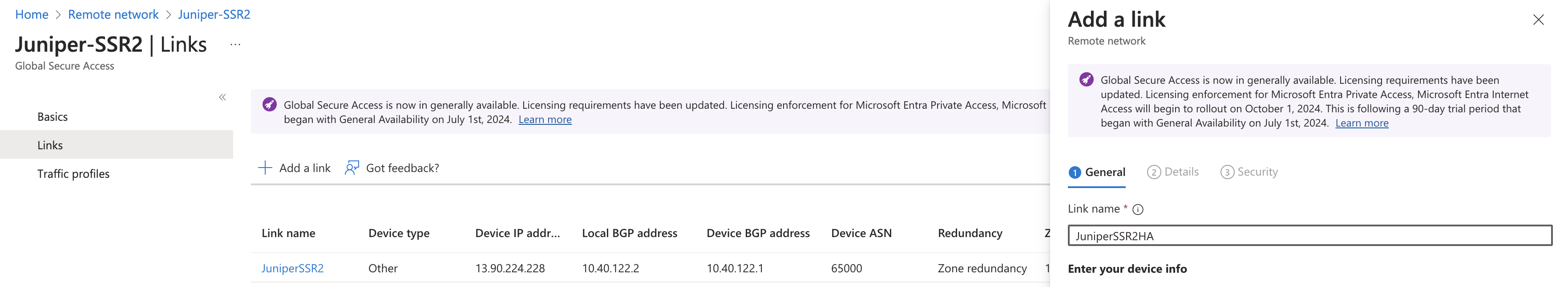
- Select the + Add a link button.
- Enter the following details:
- Link name: Name of your WAN Edge device.
- Device type: Choose one of the options from the drop-down list (Other or Juniper).
- Device IP address: Public IP address of the WAN link used to connect to Microsoft.
- Device BGP address: The border gateway protocol address of the WAN Edge. This will be the Local BGP address of the WAN Edge and will be within the /29 range selected for connectivity. The reverse peer configuration will be done in Entra portal.
-
Device ASN: Provide the autonomous system number of the WAN Edge network. By
default, this value is 65000 but might be modified using Mist APIs.Note:
Microsoft limits configuration to a list of valid ASNs.
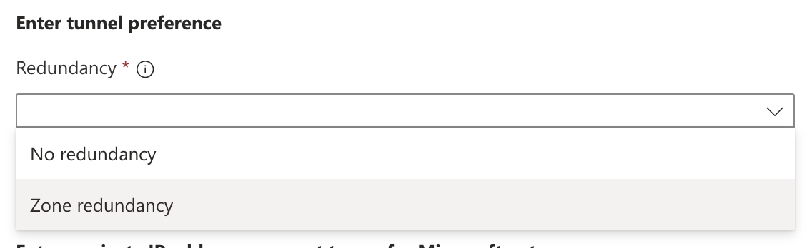
- Redundancy: Select either No redundancy or Zone redundancy for your IPsec tunnel. If you select Zone redundancy, then another unique zone redundant local BGP address is configured.
- Bandwidth capacity (Mbps): Choose the bandwidth for your IPsec tunnel.
- Local BGP address: This is a private IP address outside of the on-premises network within the /29 range selected for connectivity. For example, if the device BGP address selected for the WAN Edge peer above is 10.99.99.1, then use 10.99.99.2.

- Click Next.
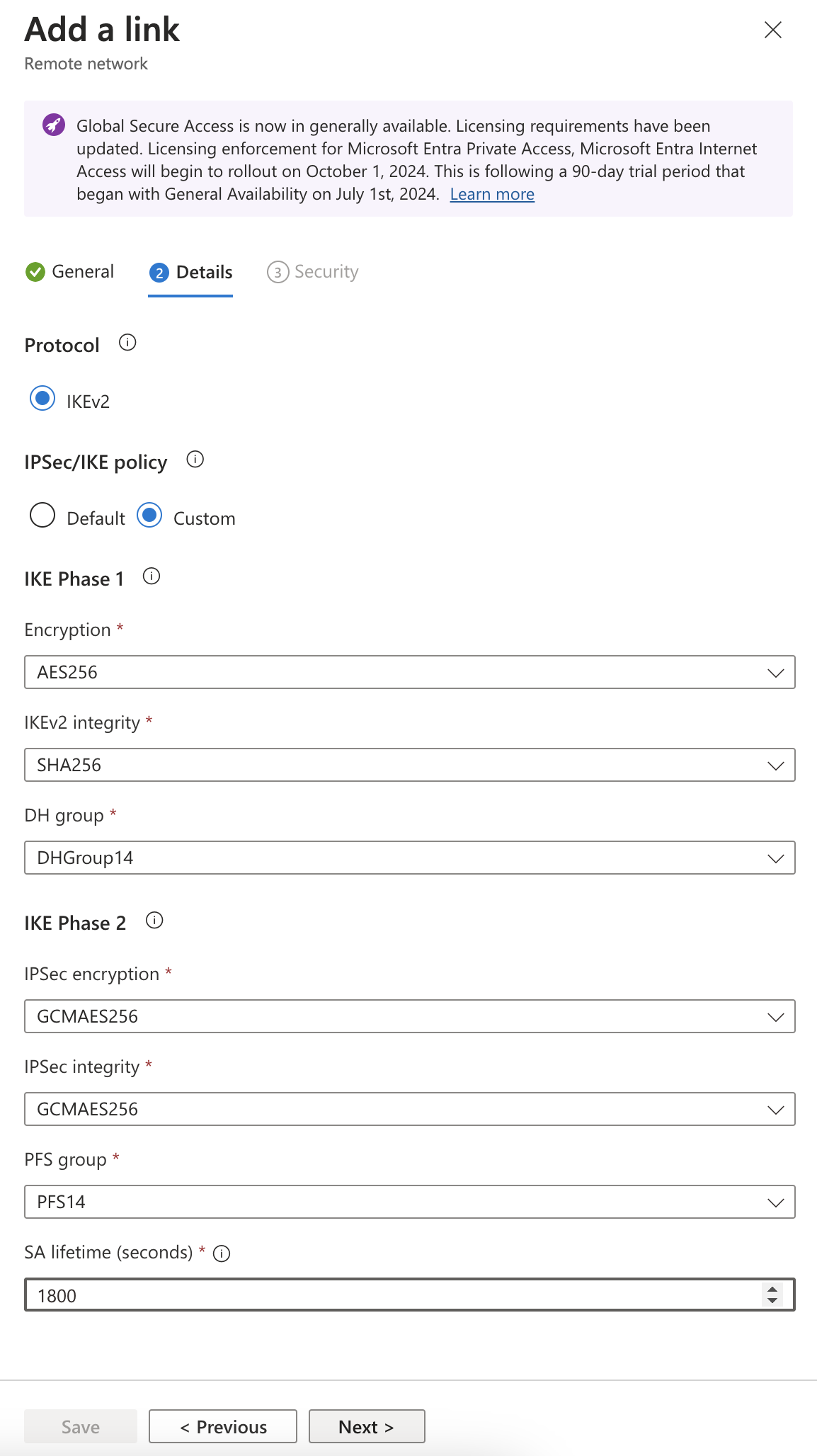
- The IPsec/IKE policy is set to Default but change it to Custom.
- After selecting Custom, select a combination of settings that match the WAN Edge.
In this example, the following settings are selected:
- Encryption
- IKEv2 integrity
- DH Group
- IPSec encryption
- IPSec integrity
- PFS Group
- SA lifetimeNote:
The IPsec/IKE policy specified must match the policy on the WAN Edge.
- Review the remote network valid configurations.
- Click Next.
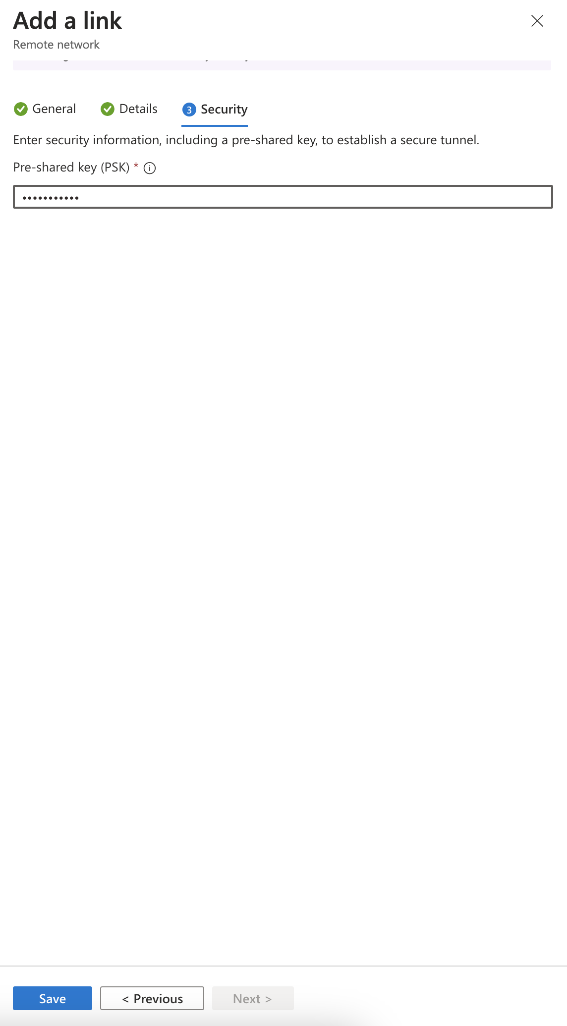
- Enter the pre-shared key (PSK). The same secret key must be used on your CPE.
- Select Add link.
Associate Traffic Profile
- Either click Next or select the Traffic profiles tab.
- Select the Microsoft 365 traffic profile.
This ensures that only Microsoft 365 traffic is forwarded to Microsoft’s SSE solution. The rest of the traffic will follow the configured Application Policy.
- Select Review + Create.
Select Create remote network to finalize the remote network configuration.

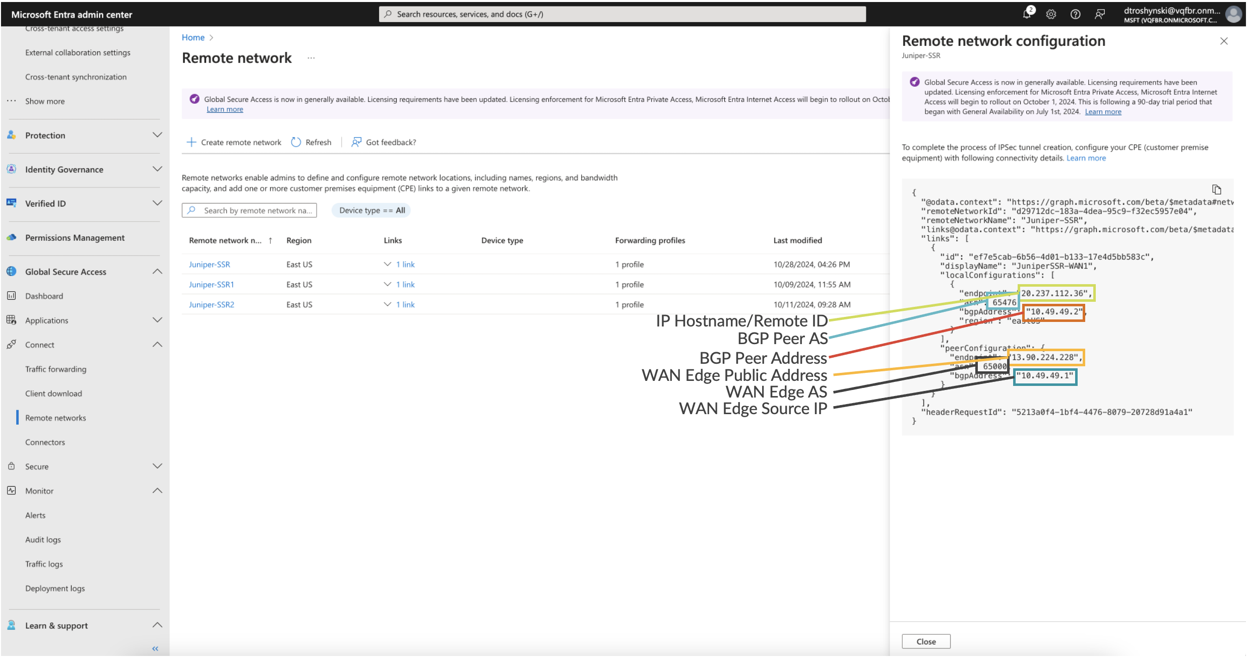
View the Network Profile
Once the remote network is created, go to the list of remote networks and select View configuration. This displays a task pane with connectivity details for the Microsoft gateway. The details include public endpoints of Microsoft’s SSE gateway that are added to the WAN, along with BGP and ASN values.
Create Application
One of the benefits of the Microsoft’s SSE solution is that Microsoft 365 applications are advertised dynamically to the WAN Edge. This means that, as protected destinations are updated and service addresses modified over time, the Microsoft’s SSE solution can dynamically advertise these routes to the WAN Edge for transport toward the service.
One of the benefits of Juniper’s AI-Driven SD-WAN is that routing policy is “Zero Trust.” This means that just because a route was learned, it does not mean a network can access the destinations reachable through the advertised route. An application policy must explicitly permit the Network to access the application.
A unique characteristic of the Session Smart Router (SSR) is that it might be configured to route unconditionally toward a destination using Steering Policy, or follow routes learned within the RIB (routing information base or route table). When a steering policy is defined for traffic to be forwarded locally toward a WAN or LAN link (for example, DIA), this policy overrides any learned routes. Therefore, an Internet service steered toward a local interface (not dynamically learned routes through the overlay), takes precedence over the learned routes if configured in the WAN Edge template.
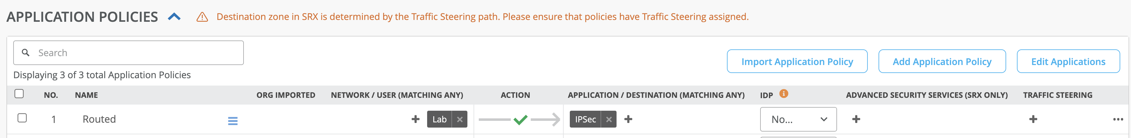
When the Microsoft’s SSE solution is used for all Internet traffic, then a simple Internet application with a prefix 0.0.0.0/0 might be used, and the user is granted access without a steering policy as shown below:
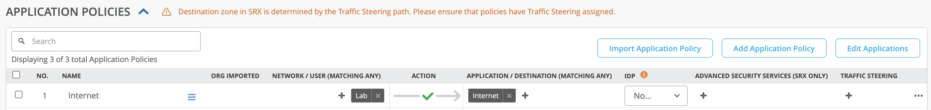
This will tell the WAN edge to allow the Network “Lab” to use any of the learned routes either through overlay or through IPsec to the Microsoft’s SSE solution.
However, if an Internet service is already created and uses DIA policies as shown in the example below, then a separate application must be created to allow the learned routes to be used first.
The way to do this is define a more specific “IPSec” application than the 0.0.0.0/0 Internet application. When the prefixes to be learned are not known (cannot be configured), then creating an IPsec application with a more specific prefix ensures the route table is imported from the IPsec BGP peer and used for the allowed networks.

- In the Mist portal, navigate to Organization > WAN > Applications.
- Click Add Applications.

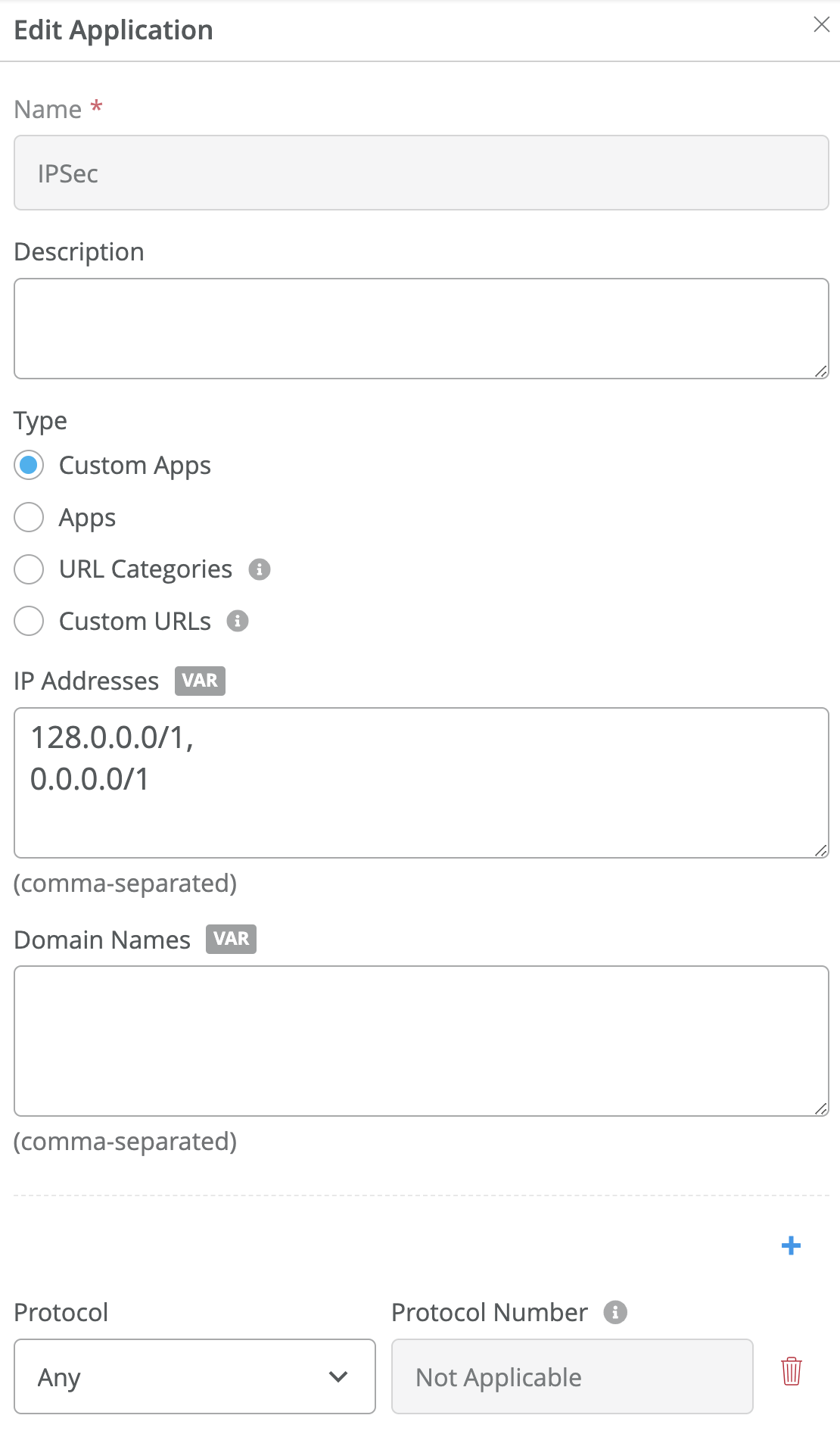
- Define an application name (for example, IPSec). See the image below.
- Select Custom Apps.
- Enter the prefixes 128.0.0.0/1 and 0.0.0.0/1 for the IP Addresses. These
prefixes are more specific than the default 0.0.0.0/0.
- Click Save and navigate to Organization > WAN > WAN Edge Templates.
Update WAN Edge Template
In the Mist portal, navigate to the WAN Edge Template for the Session Smart Router WAN Edge device.
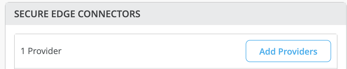
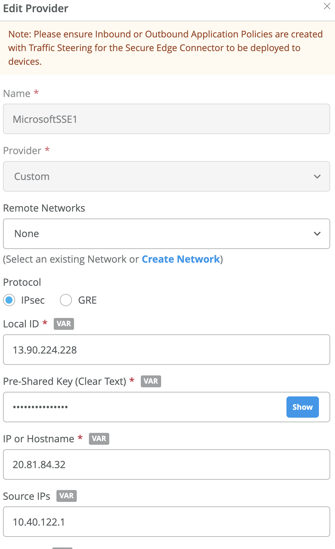
- Select Add Providers under Secure Edge Connectors to open a configuration
panel.
- Enter the following entries to match Microsoft’s SSE solution:
- Name: (for example, MicrosoftSSE)
- Provider: Custom
- Protocol: IPSec
- LocalID: <WAN Edge Public IP address>
- Pre-shared Key: <Same as MirosoftSSE>
- IP or Hostname: <Microsoft endpoint address>
- Source IP: <WAN Edge Source IP>
- Remote ID: <Microsoft endpoint address>
- WAN Interface: <Interface address with Public IP>
- IPSec Proposals:
- Encryption: aes256
- Authentication Algorithm: sha2
- DH Group: 14
- IPSec Proposals:
- Encryption Algorithm: aes_gcm256
- DH Group: 14
- SA Lifetime: 1800 seconds
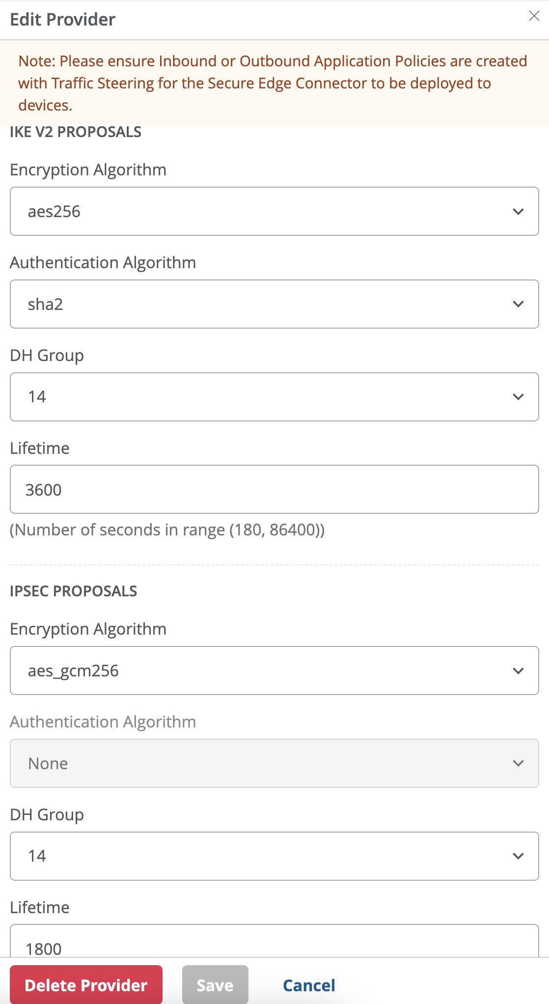
- Click Save at the bottom of the window.
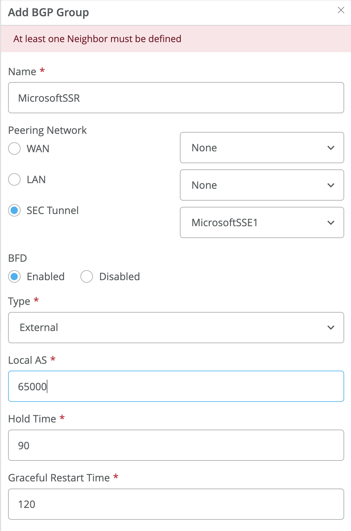
- Create a new BGP Group using the BGP dialog.
Use the values selected previously:
- Name: <name of SSE Connector>
- Type: External
- Local AS: <65000 or non-default AS for WAN Edge>
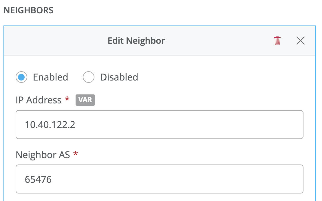
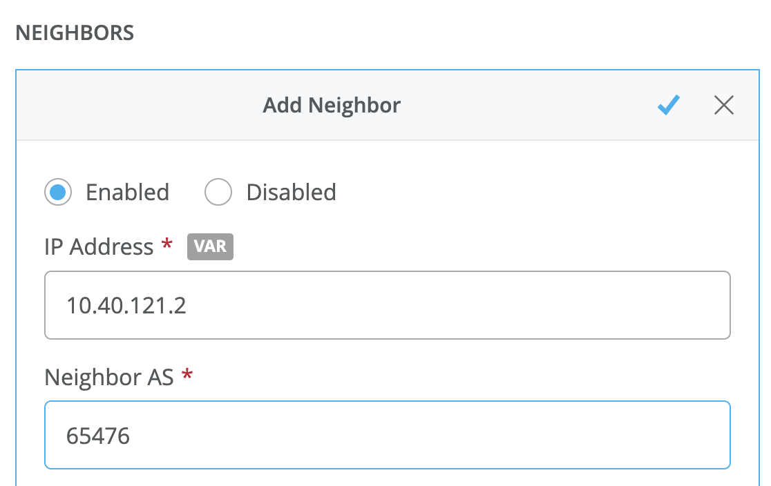
- Select Add Neighbor in the BGP dialog box.
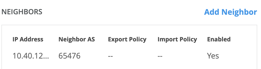
- Enter the following values for the BGP peer:
- IP Address: BGP peer address of Microsoft’s SSE solution
- Optional: Add BGP policy for import/export of routes
- Navigate to Application Policies and click Add Application Policy.

- Using the application name created in the steps above, add a policy to allow the
desired networks to reach the more specific “IPSec” application using the route table.
Leaving the Steering Policy blank instructs the SSR to use the routing table for prefixes
within the defined application range.
- Navigate to the top of the Template and click Save.
Verify Operation
Once the template is updated, an IPsec configuration will be pushed to the WAN Edge device. If this is the first time IPsec deployment, this will take some time to download the software/configuration.
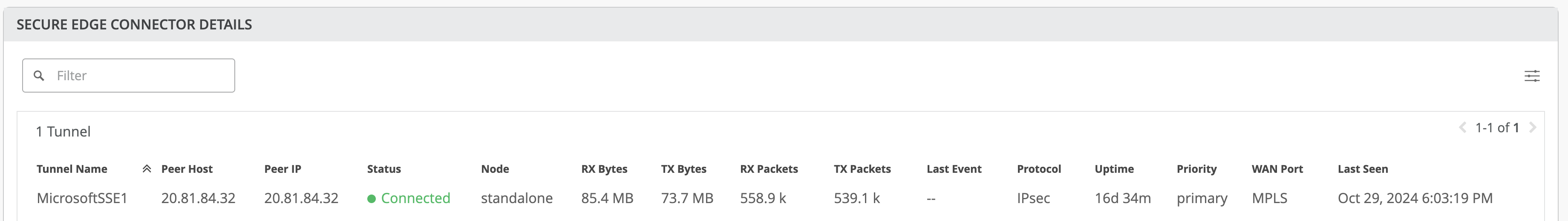
Once the IPsec configuration is deployed, you can view the IPsec status under WAN Edge > <WAN Edge Name> > Secure Edge Connector Details.
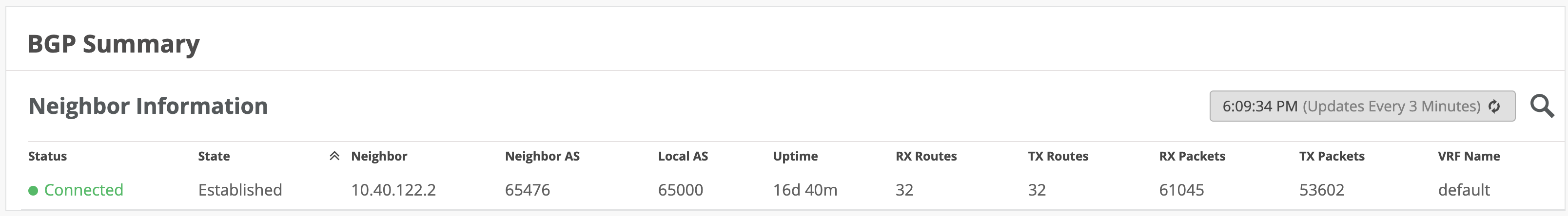
BGP neighbor status might be found under Monitor > Insights > WAN Edge.
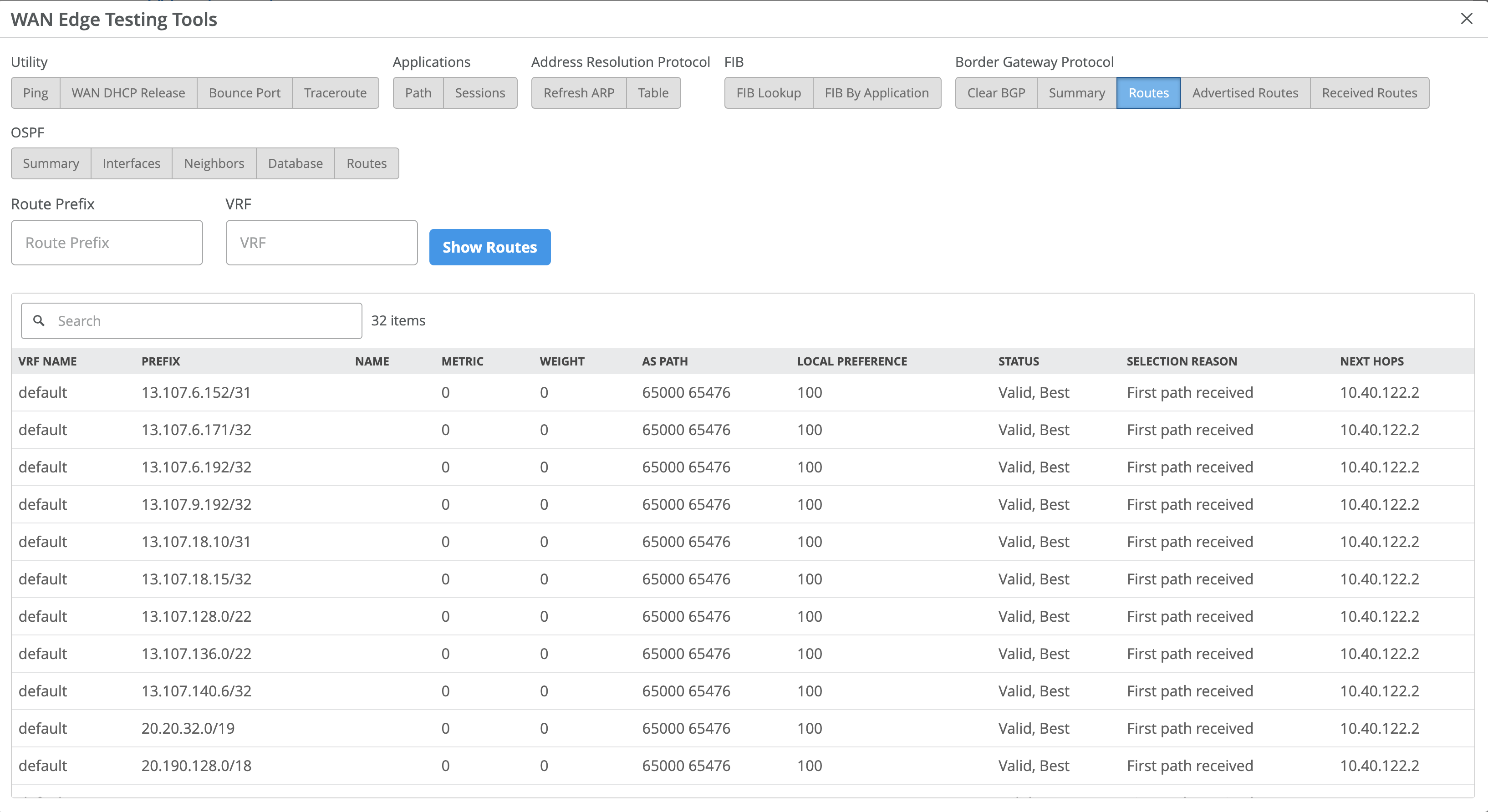
It might be useful to navigate to Testing tools to observe learned routes under WAN Edge > Utilities > Testing Tools > Routes > Show Routes. In the display below, routes learned through IPsec will be displayed with Microsoft’s SSE solution BGP peer as next hop.
Single WAN Link with Zone Redundancy on the Microsoft SSE Solution
This configuration option is illustrated in the diagram below.
In this configuration, a second BGP peer is created using zone redundancy within the Microsoft SSE solution. Follow the steps described above with the following additions:
- Ensure to select Zone redundancy when creating the link to the remote network
within the Microsoft SSE solution as shown below. This creates a second BGP peer which
might be reached through the same remote network link and IPsec tunnel from the SSR.
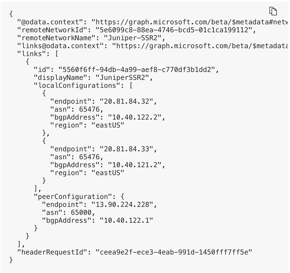
- Create a second BGP peer using the same BGP group within the device template in Mist.
The peer address might be found within the SSE configuration as shown.
Dual WAN Link Using an HA SSR with Zone Redundancy Per Tunnel on the Microsoft SSE Solution
This configuration option is illustrated in the diagram below.
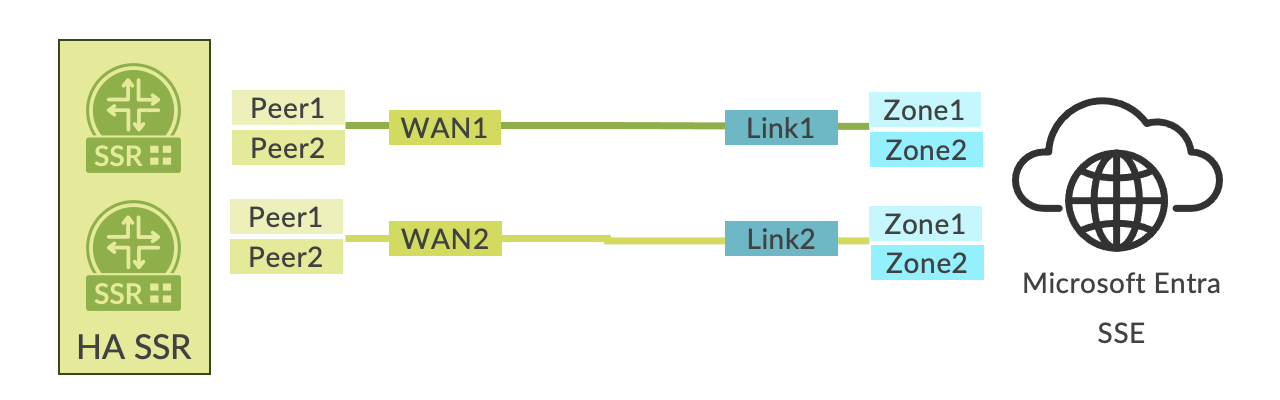
In this configuration, both a second link and a second BGP peer per link are created using zone redundancy within the Microsoft SSE solution. Follow the steps described above with the following additions:
- Ensure to select Zone redundancy when creating links as described above.
- Create the second BGP peer within the same BGP group configuration that is pointing toward the SEC Tunnel as the peering network.
- Create a second link within the Microsoft SSE solution for the same Remote network. This link might be added either during initial network configuration or added using the Remote network dialog box shown below. Select Remote network > Remote Network Name > Links > Add a link.
- Repeat the steps above for addition of another Secure Edge Connector within the device template in Mist. This provides the opportunity to steer the tunnel out a secondary interface in a high availability configuration.
- Create a second BGP Group that is assigned to the second Secure Edge Connector. This group is assigned to the second connector (SEC tunnel) as the outbound interface.
- Create a second pair of BGP peers within the BGP Group using the additional link and
BGP peering configuration within the Microsoft SSR solution.