ON THIS PAGE
Configure a DHCP Relay in EVPN-VXLAN Fabric Architecture
DHCP Relay is an essential feature in most data center deployments. This example shows how to configure DHCP Relay in an EVPN-VXLAN-based data center fabric. The document also covers other common deployment models for DHCP Relay depending on how the DHCP Server is connected to the network. See Technical Overview for details.
Requirements
This example uses the following hardware and software components:
QFX5120 switches or QFX10002 switches
Junos OS Release 18.4R2-S5
We’ve tested the configuration example using Junos OS Release 18.4R2-S5.
For details on supported platforms and Junos or Junos Evolved release support for DHCP relay, see Feature Explorer.
Overview
The DHCP Relay agent operates as the interface between DHCP Clients and the Server. DHCP Relay agent forwards incoming requests from DHCP Clients to a specified DHCP Server. In this example, we are using the Edge-routed bridging (ERB) topology as shown in Figure 1.
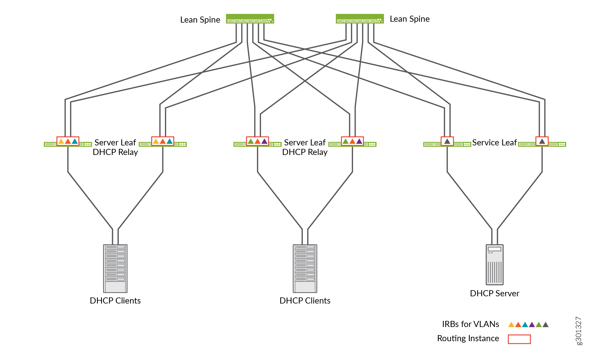
In the case of ERB, the inter-VLAN routing happens at the server leaf layer. The server leaf switches are configured to perform DHCP Relay function for the VLANs that have IRB interfaces configured on those switches.
You can apply the similar DHCP Relay configuration to a centrally-routed bridging (CRB) topology as well. In the case of CRB, Inter-VLAN routing happens at the spine switches level. So, the DHCP Relay must be configured on the spine switches.
Configuration
- DHCP Relay Configuration with Virtual Gateway Address (VGA)
- DHCP Relay Configuration with Anycast IRB
- DHCP Server Reachable only in a Service VRF
- DHCP Relay with a Single Loopback IP Address for the Entire Chassis
- DHCPv6 Relay
- Transit DHCP Relay
DHCP Relay Configuration with Virtual Gateway Address (VGA)
Step-by-Step Procedure
Do the steps that follow to configure DHCP relay for the IRB interface configured with VGA.
Enable DHCP Relay with
forward-onlyoption. The forward–only option ensures that DHCP packets are forwarded on the switch and that no DHCP Server Client bindings are created.set routing-instances TENANT_1_VRF forwarding-options dhcp-relay forward-only
Do not use any other DHCP Relay overrides.
Create and activate the DHCP Relay server group.
set routing-instances TENANT_1_VRF forwarding-options dhcp-relay server-group Server_Group1 10.101.10.31
set routing-instances TENANT_1_VRF forwarding-options dhcp-relay group Relay_Group1 active-server-group Server_Group1
The DHCP Relay server group include one or more DHCP Servers—individually identified by IP address—and a user-defined name for the servers. In this example, one DHCP server—10.101.10.31—is assigned into a DHCP server group named Server_Group1.
Associate the server group with the IRB interfaces on the leaf devices.
set routing-instances TENANT_1_VRF forwarding-options dhcp-relay group Relay_Group1 interface irb.110
set routing-instances TENANT_1_VRF forwarding-options dhcp-relay group Relay_Group1 interface irb.120
set routing-instances TENANT_1_VRF forwarding-options dhcp-relay group Relay_Group1 interface irb.130
DHCP Relay Configuration with Anycast IRB
Step-by-Step Procedure
Do the steps below to configure DHCP Relay for IRB interface configured with Anycast IP address.
Configure the DHCP Relay with the loopback address that will be used as relay source.
set routing-instances TENANT_1_VRF forwarding-options dhcp-relay group Relay_Group1 overrides relay-source lo0.101
Enable DHCP Relay option 82 with server-id-override option.
set routing-instances TENANT_1_VRF forwarding-options dhcp-relay group Relay_Group1 relay-option-82 server-id-override
Create the DHCP Relay server group and associate the server group with the IRB interfaces on the leaf devices. Same as in procedure DHCP Relay Configuration with Virtual Gateway Address (VGA).
set routing-instances TENANT_1_VRF forwarding-options dhcp-relay forward-only
set routing-instances TENANT_1_VRF forwarding-options dhcp-relay server-group Server_Group1 10.101.10.31
set routing-instances TENANT_1_VRF forwarding-options dhcp-relay group Relay_Group1 active-server-group Server_Group1
set routing-instances TENANT_1_VRF forwarding-options dhcp-relay group Relay_Group1 interface irb.110
set routing-instances TENANT_1_VRF forwarding-options dhcp-relay group Relay_Group1 interface irb.120
set routing-instances TENANT_1_VRF forwarding-options dhcp-relay group Relay_Group1 interface irb.130
Check packet capture on the DHCP Server to verify the contents of the relayed DHCP packet. Figure 2 shows the sample packet capture file.
Figure 2: Packet Capture on the DHCP Server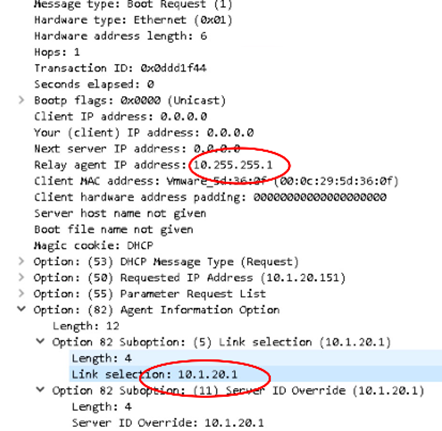
In the sample, you can notice that the relay agent IP address is the loopback IP address and the link selection attribute shows the IP address of the IRB interface.
DHCP Server Reachable only in a Service VRF
Step-by-Step Procedure
Do the steps below to configure the DHCP Server in a Service VRF.
Configure the loopback interfaces.
set interfaces lo0 unit 99 family inet address 1.1.6.2/32
set interfaces lo0 unit 100 family inet address 1.1.7.2/32
Apart from the lo0.0 interface used for VTEP, you must use a separate loopback interfaces for every routing instance. In this case, the loopback interface lo0.110 is associated with the DHCP Server VRF. The loopback interface lo0.120 is associated with the DHCP Client VRF.
Configure the routing instance where the DHCP Server is located. The DHCP Server is located in VLAN 99 with IRB.99. The IRB.99 is placed in TENANT_SERVICE_VRF.
Complete the following configurations in the Service VRF:
Configure the
dhcp-relay forward-only-repliesoption to enable DHCP response packets forwarded to the DHCP Clients in the other VRF.Configure the
auto-exportcommand along with vrf-target export and import policies that also import routes from the DHCP Client VRFs.
set routing-instances TENANT_SERVICE_VRF description VRF for DHCP server
set routing-instances TENANT_SERVICE_VRF instance-type vrf
set routing-instances TENANT_SERVICE_VRF interface irb.99
set routing-instances TENANT_SERVICE_VRF interface lo0.99
set routing-instances TENANT_SERVICE_VRF route-distinguisher 1.1.6.2:1099
set routing-instances TENANT_SERVICE_VRF vrf-import TENANT_SRV-IMPORT
set routing-instances TENANT_SERVICE_VRF vrf-export TENANT_SRV-EXPORT
set routing-instances TENANT_SERVICE_VRF vrf-target target:99:65001
set routing-instances TENANT_SERVICE_VRF vrf-table-label
set routing-instances TENANT_SERVICE_VRF routing-options auto-export
set routing-instances TENANT_SERVICE_VRF forwarding-options dhcp-relay forward-only-replies
set policy-options policy-statement TENANT_SRV-EXPORT term Direct-Routes from protocol direct
set policy-options policy-statement TENANT_SRV-EXPORT term Direct-Routes then community add com-vrf-Tenant_SRV
set policy-options policy-statement TENANT_SRV-EXPORT term Direct-Routes then accept
set policy-options policy-statement TENANT_SRV-IMPORT term vs-Tenant_SRV from community com-vrf-Tenant_SRV
set policy-options policy-statement TENANT_SRV-IMPORT term vs-Tenant_SRV then accept
set policy-options policy-statement TENANT_100-IMPORT term vs-Tenant_100 from community com-vrf-Tenant_100
set policy-options policy-statement TENANT_100-IMPORT term vs-Tenant_100 then accept
set community com-vrf-Tenant_SRV member target:99:65001
set community com-vrf-Tenant_100 member target:100:65001
Configure the routing instances where the DHCP Clients are located.
In this case, the DHCP Clients are located in VLAN 10 and VLAN 20 with corresponding IRB interfaces—IRB.10 and IRB.20. The IRB.10 and IRB.20 are part of the routing instance TENANT_CLIENT_VRF1.
Configure the following in the DHCP Client VRF:
Configure the
dhcp-relay forward-only routing-instance
<name>
option. This configuration specifies the routing instance where the DHCP Server is located. In this case, it is the "TENANT_SERVICE_VRF".Configure the
auto-exportcommand to enable the routes from the DHCP Client VRF exported into the DHCP Server VRF.
set routing-instances TENANT_CLIENT_VRF1 description "VRF for DHCP Clients in VRF1”
set routing-instances TENANT_CLIENT_VRF1 instance-type vrf
set routing-instances TENANT_CLIENT_VRF1 interface irb.10
set routing-instances TENANT_CLIENT_VRF1 interface irb.20
set routing-instances TENANT_CLIENT_VRF1 interface lo0.100
set routing-instances TENANT_CLIENT_VRF1 route-distinguisher 1.1.7.2:1100
set routing-instances TENANT_CLIENT_VRF1 vrf-target target:100:65001
set routing-instances TENANT_CLIENT_VRF1 vrf-table-label
set routing-instances TENANT_CLIENT_VRF1 routing-options auto-export
set routing-instances TENANT_CLIENT_VRF1 forwarding-options dhcp-relay forward-only routing-instance TENANT_SERVICE_VRF
set routing-instances TENANT_CLIENT_VRF1 forwarding-options dhcp-relay forward-only-replies
set routing-instances TENANT_CLIENT_VRF1 forwarding-options dhcp-relay server-group DHCP_SERVER_GROUP_1
set routing-instances TENANT_CLIENT_VRF1 forwarding-options dhcp-relay group Relay_Group1 active-server-group DHCP_SERVER_GROUP_1
set routing-instances TENANT_CLIENT_VRF1 forwarding-options dhcp-relay group Relay_Group1 overrides relay-source lo0.100
set routing-instances TENANT_CLIENT_VRF1 forwarding-options dhcp-relay group Relay_Group1 relay-option-82 server-id-override
set routing-instances TENANT_CLIENT_VRF1 forwarding-options dhcp-relay group Relay_Group1 interface irb.10
set routing-instances TENANT_CLIENT_VRF1 forwarding-options dhcp-relay  group  Relay_Group1  interface irb.20
DHCP Relay with a Single Loopback IP Address for the Entire Chassis
Step-by-Step Procedure
Do the steps that follow to configure DHCP Relay with a single loopback IP address for the entire chassis.
Configure the loopback interfaces.
set interfaces lo0 unit 0 family inet address 1.1.5.2/32 preferred
set interfaces lo0 unit 99 family inet address 1.1.5.2/32
set interfaces lo0 unit 100 family inet address 1.1.5.2/32
set interfaces lo0 unit 101 family inet address 1.1.5.2/32
Configure the routing instance where the DHCP Server is located.
set routing-instances TENANT_SERVICE_VRF description "VRF for DHCP server“
set routing-instances TENANT_SERVICE_VRF instance-type vrf
set routing-instances TENANT_SERVICE_VRF interface irb.99
set routing-instances TENANT_SERVICE_VRF interface lo0.99
set routing-instances TENANT_SERVICE_VRF route-distinguisher 1.1.5.2:1099
set routing-instances TENANT_SERVICE_VRF vrf-import TENANT_SRV-IMPORT
set routing-instances TENANT_SERVICE_VRF vrf-export TENANT_SRV-EXPORT
set routing-instances TENANT_SERVICE_VRF vrf-target target:99:65001
set routing-instances TENANT_SERVICE_VRF vrf-table-label
set routing-instances TENANT_SERVICE_VRF routing-options auto-export
set routing-instances TENANT_SERVICE_VRF forwarding-options dhcp-relay forward-only-replies
set policy-options policy-statement TENANT_SRV-EXPORT term Direct-Routes from protocol direct
set policy-options policy-statement TENANT_SRV-EXPORT term Direct-Routes then community add com-vrf-Tenant_SRV
set policy-options policy-statement TENANT_SRV-EXPORT term Direct-Routes then accept
set policy-options policy-statement TENANT_SRV-IMPORT term vs-Tenant_SRV from community com-vrf-Tenant_SRV
set policy-options policy-statement TENANT_SRV-IMPORT term vs-Tenant_SRV then accept
set policy-options policy-statement TENANT_100-IMPORT term vs-Tenant_100 from community com-vrf-Tenant_100
set policy-options policy-statement TENANT_100-IMPORT term vs-Tenant_100 then accept
set policy-options policy-statement TENANT_100-IMPORT term vs-Tenant_101 from community com-vrf-Tenant_101
set policy-options policy-statement TENANT_100-IMPORT term vs-Tenant_101 then accept
set community com-vrf-Tenant_SRV member target:99:65001
set community com-vrf-Tenant_100 member target:100:65001
set community com-vrf-Tenant_100 member target:101:65001
Configure the routing instances where the DHCP Clients are located.
set routing-instances TENANT_CLIENT_VRF1 description "VRF for DHCP Clients in VRF1”
set routing-instances TENANT_CLIENT_VRF1 instance-type vrf
set routing-instances TENANT_CLIENT_VRF1 interface irb.10
set routing-instances TENANT_CLIENT_VRF1 interface irb.20
set routing-instances TENANT_CLIENT_VRF1 interface lo0.100
set routing-instances TENANT_CLIENT_VRF1 route-distinguisher 1.1.5.2:1100
set routing-instances TENANT_CLIENT_VRF1 vrf-target target:100:65001
set routing-instances TENANT_CLIENT_VRF1 vrf-table-label
set routing-instances TENANT_CLIENT_VRF1 routing-options auto-export
set routing-instances TENANT_CLIENT_VRF1 forwarding-options  dhcp-relay  forward-only  routing-instance TENANT_SERVICE_VRF
set routing-instances TENANT_CLIENT_VRF1 forwarding-options dhcp-relay forward-only-replies
set routing-instances TENANT_CLIENT_VRF1 forwarding-options dhcp-relay server-group DHCP_SERVER_GROUP_1
set routing-instances TENANT_CLIENT_VRF1 forwarding-options dhcp-relay group Relay_Group1 active-server-group DHCP_SERVER_GROUP_1
set routing-instances TENANT_CLIENT_VRF1 forwarding-options dhcp-relay  group  Relay_Group1  overrides relay-source lo0.100
set routing-instances TENANT_CLIENT_VRF1 forwarding-options dhcp-relay group Relay_Group1 relay-option-82 server-id-override
set routing-instances TENANT_CLIENT_VRF1 forwarding-options dhcp-relay  group  Relay_Group1  interface irb.10
set routing-instances TENANT_CLIENT_VRF1 forwarding-options dhcp-relay  group  Relay_Group1  interface irb.20
set routing-instances TENANT_CLIENT_VRF2 description "VRF for DHCP Clients in VRF2”
set routing-instances TENANT_CLIENT_VRF2 instance-type vrf
set routing-instances TENANT_CLIENT_VRF2 interface irb.20
set routing-instances TENANT_CLIENT_VRF2 interface lo0.101
set routing-instances TENANT_CLIENT_VRF2 route-distinguisher 1.1.5.2:1101
set routing-instances TENANT_CLIENT_VRF2 vrf-target target:101:65001
set routing-instances TENANT_CLIENT_VRF2 vrf-table-label
set routing-instances TENANT_CLIENT_VRF2 routing-options auto-export
set routing-instances TENANT_CLIENT_VRF2 f orwarding-options  dhcp-relay  forward-only  routing-instance TENANT_SERVICE_VRF
set routing-instances TENANT_CLIENT_VRF2 forwarding-options dhcp-relay forward-only-replies
set routing-instances TENANT_CLIENT_VRF2 forwarding-options dhcp-relay server-group DHCP_SERVER_GROUP_1
set routing-instances TENANT_CLIENT_VRF2 forwarding-options dhcp-relay group Relay_Group1 active-server-group DHCP_SERVER_GROUP_1
set routing-instances TENANT_CLIENT_VRF2 forwarding-options dhcp-relay  group  Relay_Group1  overrides relay-source lo0.101
set routing-instances TENANT_CLIENT_VRF2 forwarding-options dhcp-relay group Relay_Group1 relay-option-82 server-id-override
set routing-instances TENANT_CLIENT_VRF2  forwarding-options dhcp-relay  group  Relay_Group1  interface irb.20
DHCPv6 Relay
Step-by-Step Procedure
Do the steps below to configure the DHCP6 Relay.
Configure the DHCPv6 Relay in the routing instance.
set interfaces irb unit 110 virtual-gateway-accept-data
set interfaces irb unit 110 family inet6 address 2001:db8::10:1:110:1/112
set interfaces lo0 unit 110 family inet address 192.168.110.1/32
set interfaces lo0 unit 110 family inet6 address 2001:db8::192:168:110:1/128
set routing-instances TENANT_CLIENT_VRF1 forwarding-options dhcp-relay dhcpv6 overrides relay-source lo0.110
set routing-instances TENANT_CLIENT_VRF1 forwarding-options dhcp-relay dhcpv6 forward-only
set routing-instances TENANT_CLIENT_VRF1 forwarding-options dhcp-relay dhcpv6 forward-only-replies
set routing-instances TENANT_CLIENT_VRF1 forwarding-options dhcp-relay dhcpv6 group all interface irb.110
set routing-instances TENANT_CLIENT_VRF1 forwarding-options dhcp-relay dhcpv6 group all interface irb.120
set routing-instances TENANT_CLIENT_VRF1 forwarding-options dhcp-relay dhcpv6 group all interface irb.130
Configure the IRB interfaces to send router advertisement messages with a default gateway address and the IPv6 prefix length information.
The configuration enables the DHCPv6 Clients to identify the prefix length and the default gateway because the DHCPv6 Server does not provide the information.
set protocols router-advertisement interface irb.110 preference high
set protocols router-advertisement interface irb.110 max-advertisement-interval 60
set protocols router-advertisement interface irb.110 managed-configuration
set protocols router-advertisement interface irb.110 other-stateful-configuration
set protocols router-advertisement interface irb.110 solicit-router-advertisement-unicast
set protocols router-advertisement interface irb.110 prefix 2001:db8:0:0:10:1:110::/112 no-autonomous
set protocols router-advertisement interface irb.110 prefix ::/0 no-autonomous
set protocols router-advertisement interface irb.120 preference high
set protocols router-advertisement interface irb.120 max-advertisement-interval 60
set protocols router-advertisement interface irb.120 managed-configuration
set protocols router-advertisement interface irb.120 other-stateful-configuration
set protocols router-advertisement interface irb.120 solicit-router-advertisement-unicast
set protocols router-advertisement interface irb.120 prefix 2001:db8:0:0:10:1:120::/112 no-autonomous
set protocols router-advertisement interface irb.120 prefix ::/0 no-autonomous
set protocols router-advertisement interface irb.130 preference high
set protocols router-advertisement interface irb.130 max-advertisement-interval 60
set protocols router-advertisement interface irb.130 managed-configuration
set protocols router-advertisement interface irb.130 other-stateful-configuration
set protocols router-advertisement interface irb.130 solicit-router-advertisement-unicast
set protocols router-advertisement interface irb.130 prefix 2001:db8:0:0:10:1:130::/112 no-autonomous
set protocols router-advertisement interface irb.130 prefix ::/0 no-autonomous
Step-by-Step Procedure
Verification for DHCPv6 Relay
Verify DHCPv6 Solicit Message
Use the packet capture details of the DHCPv6 solicit message, see Figure 3.
Figure 3: Packet Capture of the DHCPv6 Solicit Message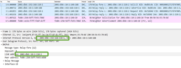
In the packet capture file, you can see information of the DHCPv6 solicit message on the DHCPv6 Server. The output indicates that the source address of the DHCPv6 relay packet is the loopback IPv6 address of the VRF on the leaf device. The link address field indicates the prefix pool that needs to be selected by the DHCPv6 Server for address assignment.
Verify DHCPv6 Reply Message Details
Use the packet capture details of the DHCPv6 reply message, see Figure 4
Figure 4: Packet Capture of the DHCPv6 Reply Message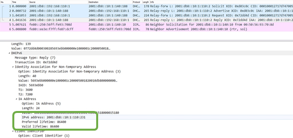
In the packet capture file, you can see information of the DHCPv6 reply message sent by the DHCPv6 Server. The DHCPv6 reply is sent to the loopback address in the VRF on the leaf device. The fields indicate that the DHCPv6 Server is sending the assigned IP prefix for the endpoint and lifetime information. The reply message does not include prefix length and the default gateway address.
Verify DHCPv6 Client Details
Verify router advertisement messages on the DHCPv6 Client.
Use the packet capture details of the DHCPv6 solicit message, see Figure 5
Figure 5: Packet Capture of the DHCPv6 Solicit Message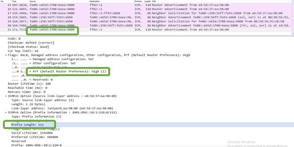
In the packet capture file, you can see information of the DHCPv6 Client. Here, you can see that the router advertisement message is providing the prefix length information along with the default gateway IP address as the link local IP address of the IRB interface.
Transit DHCP Relay
Validation
To confirm that the configuration is working properly, perform the following tasks:
Check DHCP Relay Statistics
Purpose
Verify that the DHCP relay is functioning.
Action
From operational mode:
user@host>show dhcp relay statistics
show dhcp relay statistics routing-instance Tenant1_VRF
Packets dropped:
    Total                      0

Messages received:
    BOOTREQUEST                1
    DHCPDECLINE                0
    DHCPDISCOVER               0
    DHCPINFORM                 0
    DHCPRELEASE                0
    DHCPREQUEST                1
    DHCPLEASEACTIVE            0
    DHCPLEASEUNASSIGNED        0
    DHCPLEASEUNKNOWN           0
    DHCPLEASEQUERYDONE         0

Messages sent:
    BOOTREPLY                  1
    DHCPOFFER                  0
    DHCPACK                    1
    DHCPNAK                    0
    DHCPFORCERENEW             0
    DHCPLEASEQUERY             0
    DHCPBULKLEASEQUERY         0

Packets forwarded:
    Total                      2
    BOOTREQUEST                1
    BOOTREPLY                  1
Enable Tracing Options for DHCP
Purpose
Enable tracing options for the DHCP Relay agent.
Action
Use the following commands from edit mode:
user@host> set system processes dhcp-service traceoptions file jdhcpd
user@host> set system processes dhcp-service traceoptions file size 1g
user@host> set system processes dhcp-service traceoptions level all
DHCP Log Files
Purpose
View DHCP log files to get DHCP services details.
Action
From operational mode:
user@host>show log jdhcpd

Nov 19 00:43:00.972038 [MSTR][DEBUG][default:Tenant1_VRF][RLY][INET][irb.110] jdhcpd_io_process_ip_packet: LOCAL: recv pkt; sa 0.0.0.0; da 255.255.255.255; src_port 68; dst_port 67; len 300
Nov 19 00:43:00.972074 [MSTR][DEBUG][default:Tenant1_VRF][RLY][INET][irb.110] --[ DHCP/BOOTP   from == 0.0.0.0, port == 68 ]--
Nnt1_VRF][RLY][INET][irb.110] --[ OPTION code  50, len   4, data 0a 01 6e c9 ]--


..........output truncated.............]


19 00:43:00.972320 [MSTR][DEBUG][default:Tenant1_VRF][RLY][INET][irb.110] --[ OPTION code  12, len  12, data 6b 72 69 73 68 6e 61 6e 2d 76 6d 31 ]--
Nov 19 00:43:00.972345 [MSTR][DEBUG][default:Tenant1_VRF][RLY][INET][irb.110] --[ OPTION code  55, len  19, data 01 1c 02 79 0f 06 0c 28 29 2a 1a 77 03 79 f9 21 fc 2a 11 ]--
Nov 19 00:43:00.972361 [MSTR][INFO] [default:Tenant1_VRF][RLY][INET][irb.110] --[ OPTION code 255, len   0 ]--
Nov 19 00:43:00.972386 [MSTR][DEBUG] sus_name_get: Extracted ifd_name = lo0
Nov 19 00:43:00.972407 [MSTR][DEBUG] client_key_compose: Composing key (0xa74e2c0) for cid_l 0, cid NULL, mac 00 50 56 93 eb b0, htype 1, subnet 192.168.110.1, ifindx 0, opt82_l 0, opt82 NULL
Nov 19 00:43:00.972424 [MSTR][DEBUG] client_key_compose: Successfully composed CK_TYPE_HW_ADDR_ON_SUBNET (2) client key object.

Nov 19 00:43:00.991497 [MSTR][DEBUG] jdhcpd_hex_dump: 00 00 01 8b 00 00 02 2d 00 00 02 42 00 00 00 00
Nov 19 00:43:00.991509 [MSTR][DEBUG] jdhcpd_hex_dump: ab ad d0 0d 00 00 00 00 00 00 45 00 01 55 61 c6
Nov 19 00:43:00.991521 [MSTR][DEBUG] jdhcpd_hex_dump: 00 00 00 00 00 00 00 00 45 00 01 55 61 c6 40 00
Nov 19 00:43:00.991533 [MSTR][DEBUG] jdhcpd_hex_dump: 3f 11 2f 6b 0a 01 70 bc c0 a8 6e 01 00 43 00 43
Nov 19 00:43:00.991546 [MSTR][DEBUG] jdhcpd_hex_dump: 01 41 55 d4
Nov 19 00:43:00.991560 [MSTR][INFO] [irb.110] jdhcpd_io_get_ifs: The L3 interface is 557 and L2 interface is 578, using the L3 interface
Nov 19 00:43:00.992565 [MSTR][INFO] [default:Tenant1_VRF][RLY][INET][irb.110] jdhcpd_io_send_packet_legacy: Set the outgoing if to 557
Nov 19 00:43:00.992640 [MSTR][INFO] [default:Tenant1_VRF][RLY][INET][irb.110] jdhcpd_io_send_packet_legacy: DHCP PDU from 192.168.110.1 to 10.1.110.201 port 68 out interface 557 len 329


.........output truncated.............]
Meaning
The sample output shows the DHCP log messages in the messages file. The output command shown in the document is truncated for easy readability.