How to Configure OTT DCI in an EVPN Network
Requirements
This configuration example uses the following devices and software versions:
Spine devices consisting of QFX5120-32C switches running Junos OS Release 19.1R3-S2 in both DCs.
Leaf devices consisting of QFX5110-48S switches running Junos OS Release 18.4R2-S5 in DC1.
Leaf devices consisting of QFX5120-48Y switches running Junos OS Release 18.4R2-S5 in DC2.
Overview
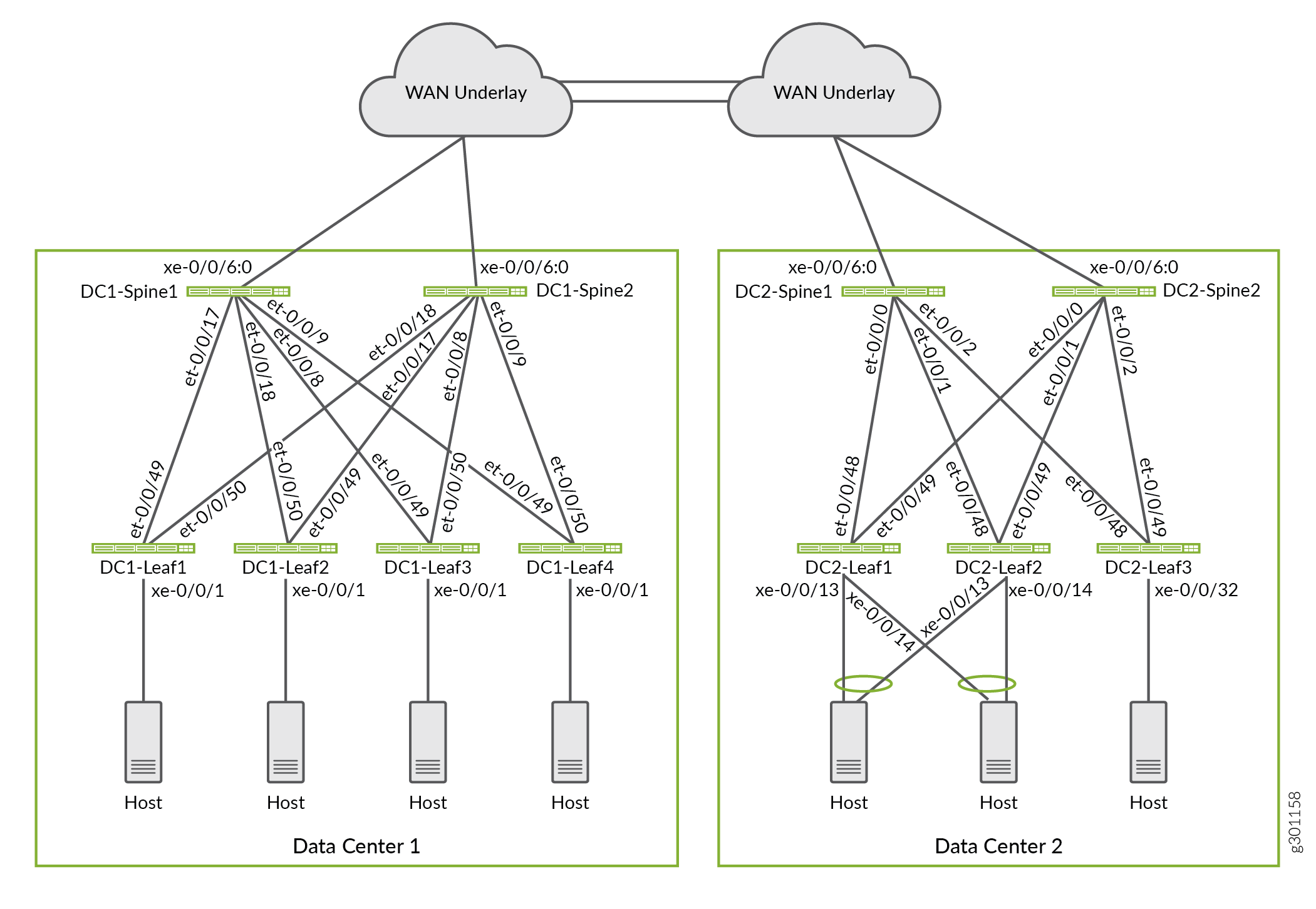
In this deployment, we use an architecture with two data center fabric networks that have been configured in an edge-routed bridging (ERB) overlay model. The data centers are interconnected with a Layer 3 IP underlay network. Figure 1 shows the WAN connectivity that provides the underlay transport between the two data centers. We use an over-the-top EVPN-VXLAN DCI architecture to provide both Layer 2 and Layer 3 connectivity for endpoints and virtual machines in the two data centers.
For this example, some VLANs are configured to exist only within a specific data center while other VLANs span across the two data centers. Figure 2 shows the VLANs that are configured in the two data centers. We configure the VLANs as follows:
VLANs 10, 11, and 12 are local to Data Center 1. The endpoints on these VLANs use Layer 3 routing to reach other VLANs in Data Center 2.
VLANs 170, 171, and 172 are local to Data Center 2. The endpoints on these VLANs use Layer 3 routing to reach other VLANs in Data Center 1.
VLANs 202 and 203 are common to Data Center 1 and Data Center 2. These VLANs stretch across all leaf devices in both data centers. The endpoints on these VLANs use Layer 2 bridging to reach the endpoints in the other data center.
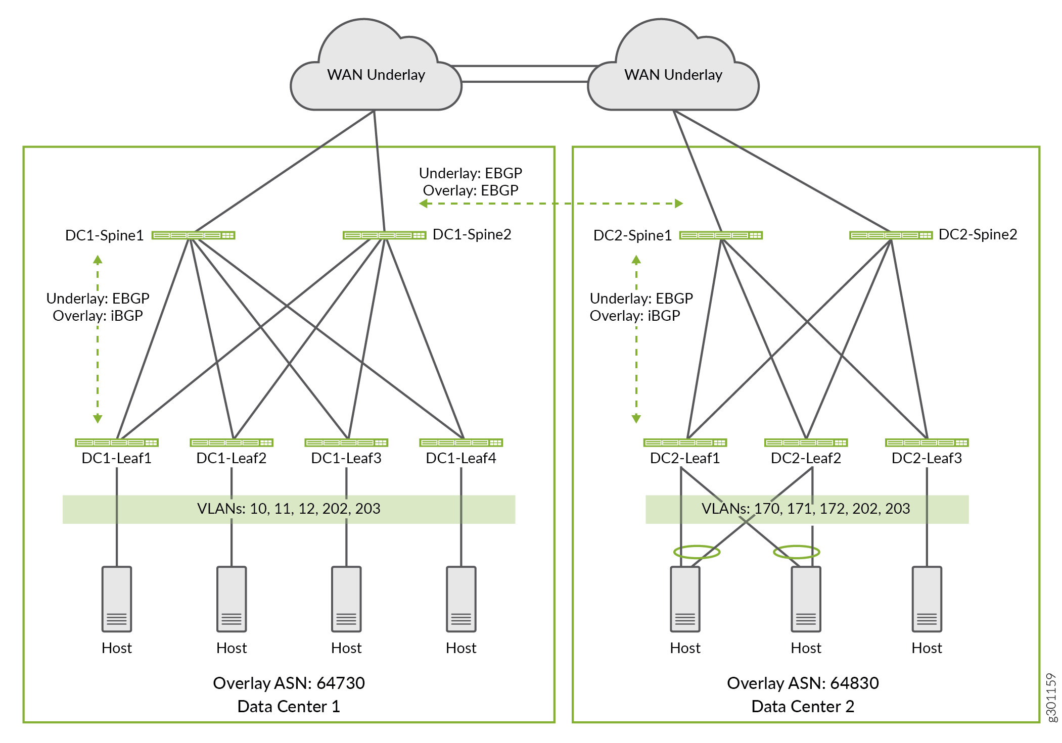
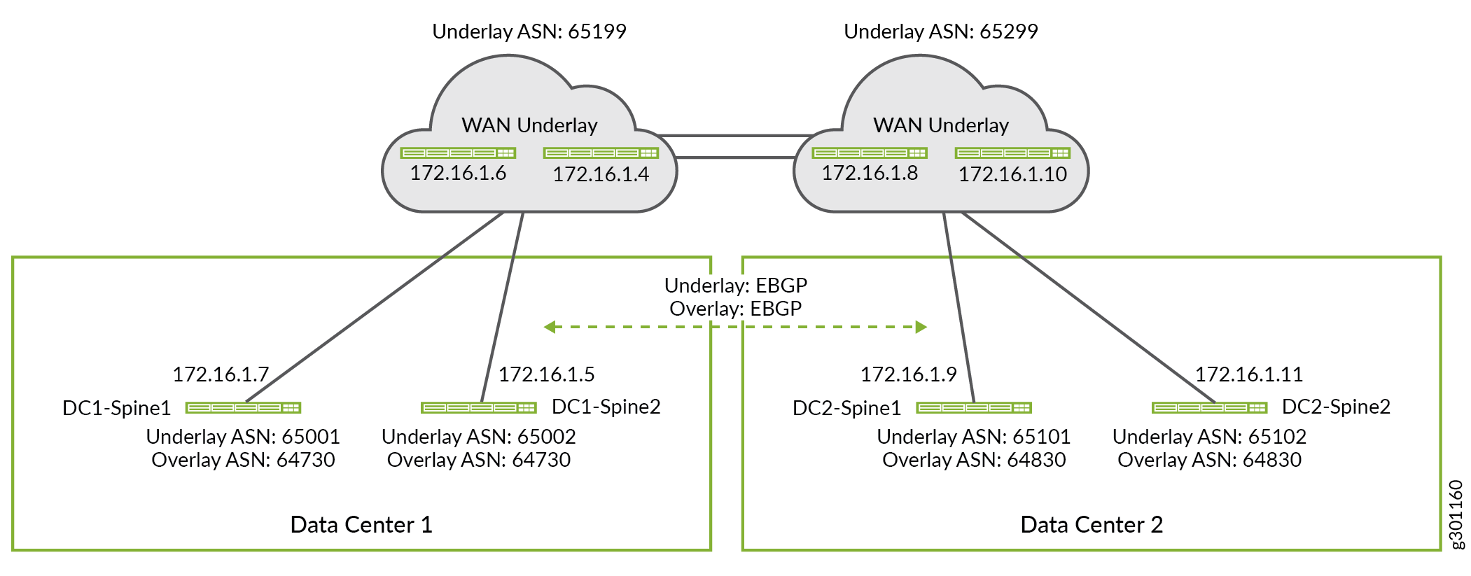
You can use any routing protocol in the underlay network. The underlay routing protocol enables devices to exchange loopback IP addresses with each other. In this example eBGP is used as the underlay routing protocol within each data center fabric. The eBGP protocol is also used to extend the underlay network across the WAN connection between the two data centers. You can use either iBGP or eBGP as the overlay routing protocol between the DCs. The choice depends on whether you use the same or different autonomous system numbers for your data centers. In this example, we will use iBGP for the overlay protocol within a fabric and eBGP between the two data centers. Figure 3 shows the autonomous system numbers and IP addresses used in this example.
Configure the Border Spine Devices for WAN Connectivity
Requirements
Border Spine WAN Underlay configuration
The configurations shown on this page are established on a pre-existing EVPN fabric with an operational underlay and overlay network. In other words, this section shows only the additional configurations that are needed to extend the DC underlay to a WAN cloud. In contrast, the detailed configurations show the full configuration of each DC device.
This section shows how to configure the WAN underlay configuration for border spine devices. For brevity, we will only show the steps for configuring one spine device in each data center. You can configure the other border spine devices by applying similar configuration steps.
Repeat these procedures for all border spine devices in each data center.
Refer to the Detailed Configurations for the EVPN-VXLAN Network for the Data Centers for the complete configurations used in this example.
Border Spine WAN Underlay
Procedure
Step-by-Step Procedure
Add the WAN peering session to the existing underlay group on Data Center 1 Spine 1 (DC1-Spine1). The border spine devices use the WAN underlay network to exchange loopback address information between the data centers. This in turn allows the spine devices to form an eBGP overlay connection across the wan cloud.
set protocols bgp group UNDERLAY neighbor 172.16.1.6 peer-as 65199
In this example the WAN router peering is added to the pre-existing
UNDERLAYBGP peer group. Because this group is already configured as part of the DC’s underlay, you only need to add the WAN router as a neighbor to the existingUNDERLAYgroup.Add the WAN peering to the existing
UNDERLAYgroup on Data Center 2 Spine 1 (DC2-Spine1).set protocols bgp group UNDERLAY neighbor 172.16.1.8 peer-as 65299
Configure the common WAN underlay policy used on the spine and leaf devices in both data centers. We reserve subnet 10.80.224.128/25 for loopback address in Data center 1, and subnet 10.0.0.0/24 for loopback address in Data Center 2. By specifying a reserved range of loopback addresses in our policy, we do not have to update the policy when a device is added as long as the device is configured with a reserved loopback address.
set policy-options policy-statement UNDERLAY-EXPORT term LOOPBACK from route-filter 10.80.224.128/25 orlonger
set policy-options policy-statement UNDERLAY-EXPORT term LOOPBACK from route-filter 10.0.0.0/24 orlonger
set policy-options policy-statement UNDERLAY-EXPORT term LOOPBACK then accept
set policy-options policy-statement UNDERLAY-EXPORT term DEFAULT then reject
set policy-options policy-statement UNDERLAY-IMPORT term LOOPBACK from route-filter 10.80.224.128/25 orlonger
set policy-options policy-statement UNDERLAY-IMPORT term LOOPBACK from route-filter 10.0.0.0/24 orlonger
set policy-options policy-statement UNDERLAY-IMPORT term LOOPBACK then accept
set policy-options policy-statement UNDERLAY-IMPORT term DEFAULT then reject
In this example the underlay exchanges only loopback routes both within, and between, the DCs. The import and export policies for the underlay are written in such a way that they can be used by all devices in both DCs. For example, the
UNDERLAY-EXPORTpolicy is configured to match both the local and remote DC loopback addresses. When applied to a device in DC1, only the10.80.224.128/25 orlongerterm is matched. Having the extraroute-filterterm for the loopback addresses assigned to DC2 causes no harm, and it allows the same policy to be applied to the underlay in both DCs.
Border Spine WAN Overlay
Step-by-Step Procedure
For the fabric overlay, you configure a full mesh of eBGP peering among all border spine devices in both data centers using eBGP. The spine devices function as overlay route reflectors within their respective DC. The overlay peering session extends the EVPN overlay between the DCs.
Because the inter-DC overlay session runs over a WAN cloud bidirectional failure detection (BFD) is not enabled for this peer group. BFD is enabled to run within each DC, both in the underlay and overlay.
By default eBGP changes the IP address in the Protocol
next-hop field to use its own IP address when re-advertising routes.
In this case, we want the protocol next-hop field to use the VTEP
IP address of the leaf device that originated the route. To prevent
BGP from changing the next hops of overlay routes we enable the no-nexthop-change option in the OVERLAY_INTERDC peer group.
Configure the WAN overlay network on DC1-Spine1.
set protocols bgp group OVERLAY_INTERDC type external
set protocols bgp group OVERLAY_INTERDC description "Group for overlay EBGP peering to remote DC"
set protocols bgp group OVERLAY_INTERDC multihop no-nexthop-change
set protocols bgp group OVERLAY_INTERDC local-address 10.80.224.149
set protocols bgp group OVERLAY_INTERDC family evpn signaling delay-route-advertisements minimum-delay routing-uptime 480
set protocols bgp group OVERLAY_INTERDC local-as 64730
set protocols bgp group OVERLAY_INTERDC multipath multiple-as
set protocols bgp group OVERLAY_INTERDC neighbor 10.0.0.2 peer-as 64830
set protocols bgp group OVERLAY_INTERDC neighbor 10.0.0.3 peer-as 64830
Configure the WAN overlay network on DC2-Spine1.
set protocols bgp group EVPN_FABRIC type internal
set protocols bgp group OVERLAY_INTERDC type external
set protocols bgp group OVERLAY_INTERDC description "Group for overlay EBGP peering to remote DC"
set protocols bgp group OVERLAY_INTERDC multihop no-nexthop-change
set protocols bgp group OVERLAY_INTERDC local-address 10.0.0.2
set protocols bgp group OVERLAY_INTERDC family evpn signaling delay-route-advertisements minimum-delay routing-uptime 480
set protocols bgp group OVERLAY_INTERDC local-as 64830
set protocols bgp group OVERLAY_INTERDC multipath multiple-as
set protocols bgp group OVERLAY_INTERDC neighbor 10.80.224.149 peer-as 64730
set protocols bgp group OVERLAY_INTERDC neighbor 10.80.224.150 peer-as 64730
Configure the Leaf Devices to support Layer 2 DCI
To extend Layer 2 (VLAN) connectivity across the two DCs we must configure the network to extend the Layer 2 broadcast domain for all endpoints in the shared VLAN. In this example, the endpoints on VLANs 202 and 203 belong to the same Layer 2 domain regardless of whether the endpoints are in the local or remote data centers. The goal is to extend, or stretch, these VLANs between the two DCs.
To extend Layer 2 connectivity for these shared VLANs between the DCs, you must configure the following:
-
Configure unique VXLAN network identifier (VNI) based route targets for EVPN type 2 and EVPN type 3 routes that are associated with the stretched VLANs under the
protocols evpnhierarchy. -
Apply an import policy to accept the unique route targets that are bound to the stretched VLANS using the
vrf-importcommand at theswitch-optionshierarchy. The stretched VLANS are EVPN type 2 and type 3 routes that are advertised by the remote data center.
Repeat these procedures for all leaf devices in the relevant data center. The commands
shown below are added to the existing switch-options and
protocols evpn hierarchies to stretch the shared VLANs between the two
DCs.
Procedure
Step-by-Step Procedure
Configure VNI specific targets for the stretched VLANs at Data Center 1 Leaf 1 (DC1-Leaf1).
set protocols evpn vni-options vni 1202 vrf-target target:64730:202
set protocols evpn vni-options vni 1203 vrf-target target:64730:203
Configure a VRF import policy to match the VNI targets for the stretched VLANs at Data Center 1 Leaf 1 (DC1-Leaf1). The policy also matches the default EVPN type 1 routes used for Auto-Discovery (AD). The policy itself is defined in a later step.
set switch-options vrf-import OVERLAY_IMPORT
Configure VNI specific targets for the stretched VLANs at Data Center 2 Leaf 1 (DC2-Leaf1).
set protocols evpn vni-options vni 1202 vrf-target target:64830:202
set protocols evpn vni-options vni 1203 vrf-target target:64830:203
03
Specify a VRF import policy to match on the VNI targets for the stretched VLANs at Data Center 2 Leaf 1 (DC2-Leaf1).
set switch-options vrf-import OVERLAY_IMPORT
Define the VRF import policy that you configured at the
switch-options vrf-importhierarchy in the previous step. In this example, we use unique route targets for each data center, and for each Layer 2 domain that is extended between the DCs. The policy is set to import the EVPN type 1 AD route that is associated with each DC/POD, as well as the EVPN type 2 and EVPN type 3 routes that are used by the stretched VLANs in both data centers.This policy should be configured on all leaf devices in both DCs.
Note:In your deployment you can use a common route target for the leaf devices in your data centers. When you use a common route target, the routes from the data centers will be automatically imported as part of the implicit import policy.
set policy-options policy-statement OVERLAY_IMPORT term 5 from community comm_pod1
set policy-options policy-statement OVERLAY_IMPORT term 5 then accept
set policy-options policy-statement OVERLAY_IMPORT term 10 from community comm_pod2
set policy-options policy-statement OVERLAY_IMPORT term 10 then accept
set policy-options policy-statement OVERLAY_IMPORT term 20 from community shared_202_fm_pod2
set policy-options policy-statement OVERLAY_IMPORT term 20 from community shared_202_fm_pod1
set policy-options policy-statement OVERLAY_IMPORT term 20 from community shared_203_fm_pod2
set policy-options policy-statement OVERLAY_IMPORT term 20 from community shared_203_fm_pod1
set policy-options policy-statement OVERLAY_IMPORT term 20 then accept
set policy-options community comm_pod1 members target:64730:999
set policy-options community comm_pod2 members target:64830:999
set policy-options community shared_202_fm_pod1 members target:64730:202
set policy-options community shared_202_fm_pod2 members target:64830:202
set policy-options community shared_203_fm_pod1 members target:64730:203
set policy-options community shared_203_fm_pod2 members target:64830:203
The values used for the
comm_pod1andcomm_po2communities match the values specified with thevrf-target statementunder theswitch-optionshierarchy of the leaf devices in DC1 and DC2, respectively. This is the route target that is added to all EVPN type 1 routes, which are used for auto discovery. This target is also attached to all other EVPN routes that do not have a VNI specific target specified at theprotocols evpnhierarchy.In this example the stretched VLANs are configured to use VNI specific targets. Therefore the import policy is written to match on all three of the targets used by each DC. Once again, this approach allows a common policy to be used across all leaf devices in both DCs.
Requirements
Configure the Leaf Devices to support Layer 3 DCI
EVPN type 5 routes are used for Layer 3 connectivity between DCs for VLANs that are not stretched. An EVPN type 5 route is also called an IP prefix route. In other words, a Type 5 route is used when the Layer 2 broadcast domain is confined within the data center. EVPN type 5 routes enable Layer 3 connectivity by advertising the IP prefix of the IRB interface associated with non-extended VLANs. In this example, VLANs (10, 11, 12) are confined to Data Center 1, while VLANs (170, 171, 172) are confined within Data Center 2. We establish Layer 3 inter-data center connectivity between the members of these VLANs by using IP prefix routes.
Procedure
Step-by-Step Procedure
Configure Layer 3 DCI on DC1-Leaf1 by defining a Layer 3 VRF with support for EVPN type 5 routes.
set routing-instances TENANT_1_VRF description "VRF for Tenant_1"
set routing-instances TENANT_1_VRF instance-type vrf
set routing-instances TENANT_1_VRF interface irb.10
set routing-instances TENANT_1_VRF interface irb.11
set routing-instances TENANT_1_VRF interface irb.12
set routing-instances TENANT_1_VRF interface irb.202
set routing-instances TENANT_1_VRF interface irb.203
set routing-instances TENANT_1_VRF interface lo0.1
set routing-instances TENANT_1_VRF route-distinguisher 10.80.225.140:9999
set routing-instances TENANT_1_VRF vrf-import VRF1_VRF1_T5_RT_IMPORT
set routing-instances TENANT_1_VRF vrf-export VRF1_VRF1_T5_RT_EXPORT
set routing-instances TENANT_1_VRF vrf-target target:1:65001
set routing-instances TENANT_1_VRF vrf-table-label
set routing-instances TENANT_1_VRF routing-options multipath
set routing-instances TENANT_1_VRF protocols evpn ip-prefix-routes advertise direct-nexthop
set routing-instances TENANT_1_VRF protocols evpn ip-prefix-routes encapsulation vxlan
set routing-instances TENANT_1_VRF protocols evpn ip-prefix-routes vni 9999
set routing-instances TENANT_1_VRF protocols evpn ip-prefix-routes export T5_EXPORT
Configure Layer 3 DCI on DC2-Leaf1 by defining a Layer 3 VRF with support for EVPN type 5 routes.
set routing-instances TENANT_1_VRF description "VRF for Tenant_1"
set routing-instances TENANT_1_VRF instance-type vrf
set routing-instances TENANT_1_VRF interface irb.170
set routing-instances TENANT_1_VRF interface irb.171
set routing-instances TENANT_1_VRF interface irb.172
set routing-instances TENANT_1_VRF interface irb.202
set routing-instances TENANT_1_VRF interface irb.203
set routing-instances TENANT_1_VRF interface lo0.1
set routing-instances TENANT_1_VRF route-distinguisher 10.0.1.19:9999
set routing-instances TENANT_1_VRF vrf-import VRF1_T5_RT_IMPORT
set routing-instances TENANT_1_VRF vrf-export VRF1_T5_RT_EXPORT
set routing-instances TENANT_1_VRF vrf-target target:1:65001
set routing-instances TENANT_1_VRF vrf-table-label
set routing-instances TENANT_1_VRF routing-options multipath
set routing-instances TENANT_1_VRF protocols evpn ip-prefix-routes advertise direct-nexthop
set routing-instances TENANT_1_VRF protocols evpn ip-prefix-routes encapsulation vxlan
set routing-instances TENANT_1_VRF protocols evpn ip-prefix-routes vni 9999
set routing-instances TENANT_1_VRF protocols evpn ip-prefix-routes export T5_EXPORT
Configure the Layer 3 DCI policy for all leaf devices in DC1
set policy-options policy-statement T5_EXPORT term fm_direct from protocol direct
set policy-options policy-statement T5_EXPORT term fm_direct then accept
set policy-options policy-statement T5_EXPORT term fm_static from protocol static
set policy-options policy-statement T5_EXPORT term fm_static then accept
set policy-options policy-statement T5_EXPORT term fm_v4_host from protocol evpn
set policy-options policy-statement T5_EXPORT term fm_v4_host from route-filter 0.0.0.0/0 prefix-length-range /32-/32
set policy-options policy-statement T5_EXPORT term fm_v4_host then accept
set policy-options policy-statement T5_EXPORT term fm_v6_host from protocol evpn
set policy-options policy-statement T5_EXPORT term fm_v6_host from route-filter 0::0/0 prefix-length-range /128-/128
set policy-options policy-statement T5_EXPORT term fm_v6_host then accept

set policy-options policy-statement VRF1_T5_RT_EXPORT term t1 then community add target_t5_pod1
set policy-options policy-statement VRF1_T5_RT_EXPORT term t1 then accept

set policy-options policy-statement VRF1_T5_RT_IMPORT term t1 from community target_t5_pod1
set policy-options policy-statement VRF1_T5_RT_IMPORT term t1 then accept
set policy-options policy-statement VRF1_T5_RT_IMPORT term t2 from community target_t5_pod2
set policy-options policy-statement VRF1_T5_RT_IMPORT term t2 then accept

set policy-options community target_t5_pod1 members target:64730:9999
set policy-options community target_t5_pod2 members target:64830:9999
Configure the Layer 3 DCI policy for all leaf devices in DC2
set policy-options policy-statement T5_EXPORT term fm_direct from protocol direct
set policy-options policy-statement T5_EXPORT term fm_direct then accept
set policy-options policy-statement T5_EXPORT term fm_static from protocol static
set policy-options policy-statement T5_EXPORT term fm_static then accept
set policy-options policy-statement T5_EXPORT term fm_v4_host from protocol evpn
set policy-options policy-statement T5_EXPORT term fm_v4_host from route-filter 0.0.0.0/0 prefix-length-range /32-/32
set policy-options policy-statement T5_EXPORT term fm_v4_host then accept
set policy-options policy-statement T5_EXPORT term fm_v6_host from protocol evpn
set policy-options policy-statement T5_EXPORT term fm_v6_host from route-filter 0::0/0 prefix-length-range /128-/128
set policy-options policy-statement T5_EXPORT term fm_v6_host then accept

set policy-options policy-statement VRF1_T5_RT_EXPORT term t1 then community add target_t5_pod2
set policy-options policy-statement VRF1_T5_RT_EXPORT term t1 then accept

set policy-options policy-statement VRF1_T5_RT_IMPORT term t1 from community target_t5_pod1
set policy-options policy-statement VRF1_T5_RT_IMPORT term t1 then accept
set policy-options policy-statement VRF1_T5_RT_IMPORT term t2 from community target_t5_pod2
set policy-options policy-statement VRF1_T5_RT_IMPORT term t2 then accept

set policy-options community target_t5_pod1 members target:64730:9999
set policy-options community target_t5_pod2 members target:64830:9999
Alternate Policy Configuration for Importing Route Targets
Requirements
In this example, the auto-derived route targets include the overlay AS number as part of its identifier. As a result you end up with different route targets for the same VNI in Data Center 1 and Data Center 2.
For a simpler policy configuration, you can automatically derive
route targets by including the vrf-target statement with
the auto option at the switch-options hierarchy.
When you enable vrf-target auto, Junos automatically creates
the route targets used for EVPN types 2 and type 3 routes. For EVPN-VXLAN,
the route target is automatically derived from the VXLAN network identifier
(VNI). In this example, the auto-derived EVPN type 2 and type 3 route
targets for VNI 1202 are target:64730:268436658 in Data Center 1 and
target:64830:268436658 in Data Center 2. These route targets are then
attached to associated EVPN type 2 and type 3 routes. The vrf-target
auto statement creates an implicit import policy to match on
and import the same route target values for these VNIs.
With the simpler policy the EVPN type 2 and 3 routes for VLAN
202 and 203 are not automatically imported. To import EVPN type 2
and 3 routes from a data center with a different autonomous system
number, include the vrf-target auto import-as statement.
Here is the configuration example for Leaf 1 in Data Center 1.
set switch-options vrf-import OVERLAY_IMPORT
set switch-options vrf-target target:64730:999
set switch-options vrf-target auto import-as 64830 vni-list 1202
set switch-options vrf-target auto import-as 64830 vni-list 1203
set protocols evpn extended-vni-list 110
set protocols evpn extended-vni-list 111
set protocols evpn extended-vni-list 112
set protocols evpn extended-vni-list 1202
set protocols evpn extended-vni-list 1203
set policy-options policy-statement OVERLAY_IMPORT term 5 from community comm_pod1
set policy-options policy-statement OVERLAY_IMPORT term 5 then accept
set policy-options policy-statement OVERLAY_IMPORT term 10 from community comm_pod2
set policy-options policy-statement OVERLAY_IMPORT term 10 then accept
set policy-options community comm_pod1 members target:64730:999
set policy-options community comm_pod2 members target:64830:999
Verification
Procedure
Requirements
Overview
Verify BGP Peering
- #verify-bgp-peering__d2091e390
- Verify VTEPs in a Leaf Device
- Verify EVPN type 1 Routes
- Verify EVPN Type 2 Routes
- Verify the Layer 3 DCI
Purpose
Verify the underlay, overlay, and inter-DC BGP Peering sessions.
Action
Verify that all underlay and overlay BGP peering sessions are established. This includes the eBGP overlay peering between DCs formed across the WAN cloud.
The below is taken from the DC2-Spine1 device in DC2. All BGP peering sessions should be established on all leaf and spines devices in both DCs.
user@dc2spine1> show bgp summary

Threading mode: BGP I/O
Groups: 3 Peers: 9 Down peers: 0
Table          Tot Paths  Act Paths Suppressed    History Damp State    Pending
inet.0
                      10          5          0          0          0          0
bgp.evpn.0
                      99         99          0          0          0          0
Peer                     AS      InPkt     OutPkt    OutQ   Flaps Last Up/Dwn State|#Active/Received/Accepted/Damped...
10.0.0.14             64830      11634      11582       0       1     8:49:40 Establ
  bgp.evpn.0: 36/36/36/0
10.0.0.18             64830      11646      11604       0       2     8:49:40 Establ
  bgp.evpn.0: 36/36/36/0
10.0.0.19             64830      11652      11603       0       3     8:49:38 Establ
  bgp.evpn.0: 36/36/36/0
10.80.224.149         64730      11621      11622       0       6     8:49:31 Establ
  bgp.evpn.0: 27/27/27/0
10.80.224.150         64730      11630      11600       0       6     8:49:31 Establ
  bgp.evpn.0: 27/27/27/0
172.16.0.1            65019      11640      11582       0       2     8:49:39 Establ
  inet.0: 1/1/1/0
172.16.0.3            65018      11634      11583       0       1     8:49:42 Establ
  inet.0: 1/1/1/0
172.16.1.5            65229      11678      11500       0       1     8:49:43 Establ
  inet.0: 3/8/3/0
172.16.1.8            65229      11688      11581       0       1     8:49:43 Establ
  inet.0: 3/8/3/0
Meaning
The output on DC2-Spine1 confirms all of it’s BGP sessions are established. There is an underlay and overlay session per local leaf, plus the WAN peering session, and the 2 overlay peering sessions to the spine devices in the remote DC. This brings the total number of sessions to 9. The ability to establish the overlay peering to the remote DC confirms proper underlay route exchange over the WAN cloud.
Verify VTEPs in a Leaf Device
Purpose
Verify the Layer 2 connection between two leaf devices in different data centers.
Action
Verify that VTEP interfaces are up on the leaf devices in both the local and remote data centers.
The following is a snippet of the output of VTEP status from a leaf in data center 1.
user@dc1leaf1> show interfaces vtep

Physical interface: vtep, Enabled, Physical link is Up
  Interface index: 641, SNMP ifIndex: 508
  Type: Software-Pseudo, Link-level type: VxLAN-Tunnel-Endpoint, MTU: Unlimited, Speed: Unlimited
  Device flags   : Present Running
  Link type      : Full-Duplex
  Link flags     : None
  Last flapped   : Never
    Input packets : 0
    Output packets: 0
.
.
.
  Logical interface vtep.32769 (Index 555) (SNMP ifIndex 539)
    Flags: Up SNMP-Traps Encapsulation: ENET2
    VXLAN Endpoint Type: Remote, VXLAN Endpoint Address: 10.80.224.141, L2 Routing Instance: default-switch, L3 Routing Instance: default
    Input packets : 731317
    Output packets: 469531709
    Protocol eth-switch, MTU: Unlimited
      Flags: Trunk-Mode
.
.
.
  Logical interface vtep.32770 (Index 572) (SNMP ifIndex 541)
    Flags: Up SNMP-Traps Encapsulation: ENET2
    VXLAN Endpoint Type: Remote, VXLAN Endpoint Address: 10.0.0.18, L2 Routing Instance: default-switch, L3 Routing Instance: default
    Input packets : 136973831
    Output packets: 141901343
    Protocol eth-switch, MTU: Unlimited
      Flags: Trunk-Mode
.
.
.
Meaning
The output on DC1-Leaf1 shows that Layer 2 VXLAN tunnels are created between this leaf device and the other leaf devices in the local data center fabric (the VTEP address of leaf 2 in DC1 is shown in the snippet). The output also shows VTEPs are learned between this leaf device and the other leaf devices in the remote data center fabric (the VTEP for leaf 2 in DC2 is shown in the snippet). The input and output packet counters verify successful data transmission between endpoints on these VTEPs.
Verify EVPN type 1 Routes
Purpose
Verify EVPN type 1 routes are being added to the routing table.
Action
Verify that the EVPN type1 (AD/ESI) route has been received and installed..
user@dc1leaf1>show route | match 1:10.0.0.181:10.0.0.18:0::0202020201::FFFF:FFFF/192 AD/ESI 1:10.0.0.18:0::0202020202::FFFF:FFFF/192 AD/ESI user@dc1leaf1>show route extensive | find 1:10.0.0.18:0::0202020201:1:10.0.0.18:0::0202020201::FFFF:FFFF/192 AD/ESI (1 entry, 0 announced) *BGP Preference: 170/-101 Route Distinguisher: 10.0.0.18:0 Next hop type: Indirect, Next hop index: 0 Address: 0xbd78c94 Next-hop reference count: 50 Source: 10.80.224.149 Protocol next hop: 10.0.0.18 Indirect next hop: 0x2 no-forward INH Session ID: 0x0 State: <Active Int Ext> Local AS: 64730 Peer AS: 64730 Age: 1:22 Metric2: 0 Validation State: unverified Task: BGP_64730.10.80.224.149 AS path: 64830 I Communities: target:64830:999 encapsulation:vxlan(0x8) esi-label:0x0:all-active (label 0) Import Accepted Route Label: 1 Localpref: 100 Router ID: 10.80.224.149 Secondary Tables: default-switch.evpn.0 Indirect next hops: 1 Protocol next hop: 10.0.0.18 Indirect next hop: 0x2 no-forward INH Session ID: 0x0 Indirect path forwarding next hops: 1 Next hop type: Router Next hop: 10.80.224.2 via et-0/0/49.0 Session Id: 0x0 10.0.0.18/32 Originating RIB: inet.0 Node path count: 1 Forwarding nexthops: 1 Nexthop: 10.80.224.2 via et-0/0/49.0 Session Id: 0
Display EVPN routing instance information. The snippet below is taken at leaf 1 in DC1.
user@dc1leaf1> show evpn instance extensive

Instance: __default_evpn__
  Route Distinguisher: 10.80.224.140:0
  Number of bridge domains: 0
  Number of neighbors: 0

. . .
    ESI: 00:00:00:00:00:02:02:02:02:01
      Status: Resolved
      Number of remote PEs connected: 2
        Remote PE        MAC label  Aliasing label  Mode
        10.0.0.19        1203       0               all-active
        10.0.0.18        0          0               all-active
    ESI: 00:00:00:00:00:02:02:02:02:02
      Status: Resolved
      Number of remote PEs connected: 2
        Remote PE        MAC label  Aliasing label  Mode
        10.0.0.19        0          0               all-active
        10.0.0.18        0          0               all-active

. . .
Meaning
These outputs show that DC1-Leaf1 has received EVPN
type1 (AD/ESI) routes from the remote data center. You can use the
output of the show route extensive command to show that
these routes have a route target of “target:64830:999" and that
these routes were successfully installed. The ESI 02:02:02:02:01 and
02:02:02:02:02 are Ethernet segments in the remote data center. This
output also shows the remote PEs with IP addresses of 10.0.0.18 and
10.0.0.19 are part of these Ethernet segments.
Verify EVPN Type 2 Routes
Purpose
Verify EVPN type 2 routes are being added to the routing table.
Action
Verify that an EVPN type 2 route has been received and installed in the route table on a leaf device in data center 1.
Use show route to find an endpoint in VLAN 203 that is in the remote data center.
user@dc1leaf1>show route | match 00:10:94:00:00:06

2:10.0.0.18:1::1203::00:10:94:00:00:06/304 MAC/IP
2:10.0.0.18:1::1203::00:10:94:00:00:06::10.1.203.151/304 MAC/IP
Use the detailed view for show route to see more details.
user@dc1leaf1> show route extensive | find 2:10.0.0.18:1::1203::00:10:94:00:00:06::10.1.203.151/304

2:10.0.0.18:1::1203::00:10:94:00:00:06::10.1.203.151/304 MAC/IP (1 entry, 0 announced)
        *BGP    Preference: 170/-101
                Route Distinguisher: 10.0.0.18:1
                Next hop type: Indirect, Next hop index: 0
                Address: 0xbd78c94
                Next-hop reference count: 58
                Source: 10.80.224.149
                Protocol next hop: 10.0.0.18
                Indirect next hop: 0x2 no-forward INH Session ID: 0x0
                State: <Active Int Ext>
                Local AS: 64730 Peer AS: 64730
                Age: 1:31       Metric2: 0
                Validation State: unverified
                Task: BGP_64730.10.80.224.149
                AS path: 64830 I
                Communities: target:64830:203 encapsulation:vxlan(0x8)
                Import Accepted
                Route Label: 1203
                ESI: 00:00:00:00:00:00:00:00:01:01
                Localpref: 100
                Router ID: 10.80.224.149
                Secondary Tables: default-switch.evpn.0
                Indirect next hops: 1
                        Protocol next hop: 10.0.0.18
                        Indirect next hop: 0x2 no-forward INH Session ID: 0x0
                        Indirect path forwarding next hops: 1
                                Next hop type: Router
                                Next hop: 10.80.224.2 via et-0/0/49.0
                                Session Id: 0x0
                                10.0.0.18/32 Originating RIB: inet.0
                                  Node path count: 1
                                  Forwarding nexthops: 1
                                        Nexthop: 10.80.224.2 via et-0/0/49.0
                                        Session Id: 0
Use the show vlans command to find the information
on VLAN 203.
user@dc1leaf1> show vlans v203

Routing instance        VLAN name             Tag          Interfaces
default-switch          v203                  203
                                                           esi.1860*
                                                           vtep.32769*
                                                           vtep.32770*
                                                           vtep.32772*
																				   xe-0/0/1.0*
The above output shows that VLAN 203 is configured on VTEPs
“vtep.32769 - 10.80.224.141 – DC1-Leaf2”, “vtep.32772
– 10.0.0.18 – DC2-Leaf2”, “vtep.32770 - 10.0.0.19
– DC2-Leaf1”. The output also indicates that there are
endpoints connected to VLAN v203 on these VTEPs. You can use show interfaces VTEP to get the VTEP IP address for these VTEPs.
Use the show evpn database and the show ethernet-switching-table commands to find the MAC address and IP address for these endpoints.
Use the show evpn database to find entries in the
EVPN database.
user@dc1leaf1> show evpn database neighbor 10.0.0.18

Instance: default-switch
VLAN  DomainId  MAC address        Active source                  Timestamp        IP address
     1202       3c:8c:93:2e:a8:c0  10.0.0.18                      Jul 18 23:41:54  10.1.202.18
     1203       00:10:94:00:00:06  00:00:00:00:00:02:02:02:02:01  Jul 19 03:16:42  10.1.203.151
     1203       3c:8c:93:2e:a8:c0  10.0.0.18                      Jul 18 23:41:54  10.1.203.18
Use the show ethernet-switching table command to
display information for a particular MAC address.
user@dc1leaf1> show ethernet-switching table 00:10:94:00:00:06


MAC flags (S - static MAC, D - dynamic MAC, L - locally learned, P - Persistent static
           SE - statistics enabled, NM - non configured MAC, R - remote PE MAC, O - ovsdb MAC)


Ethernet switching table : 29 entries, 29 learned
Routing instance : default-switch
   Vlan                MAC                 MAC      Logical                Active
   name                address             flags    interface              source
   v203                00:10:94:00:00:06   DR       esi.1874               00:00:00:00:00:02:02:02:02:01
Meaning
The output shows that the MAC address from a device on VLAN 203 in the remote PE has been installed in the EVPN database and is in Ethernet Switching table.
Verify the Layer 3 DCI
Purpose
Verify Layer 3 routes are installed in the routing table.
Action
Verify that an EVPN type 5 route has been received and installed in the route table on a leaf device in data center 1.
Verify that you are receiving EVPN type 5 routes from the 10.1.170.0/24, which is the subnet for VLAN 170. This VLAN is local to data center 2. To reach this subnet from Data Center 1 requires Layer 3 routing.
user@dc1leaf1> show route | match 5: | match 10.1.170.0

5:10.0.1.18:9999::0::10.1.170.0::24/248
5:10.0.1.19:9999::0::10.1.170.0::24/248

. . .
You can view more details about the EVPN type 5 route for the 10.1.170.0/24 network. Traffic sent from this leaf device for this subnet is encapsulated in VXLAN tunnel with VNI 9999 and sent to remote leaf 10.0.0.18 in data center 2.
user@dc1leaf1> show route 10.1.170.0/24 extensive

TENANT_1_VRF.inet.0: 28 destinations, 57 routes (28 active, 0 holddown, 0 hidden)
10.1.170.0/24 (3 entries, 1 announced)
TSI:
KRT in-kernel 10.1.170.0/24 -> {composite(1742)}
        *EVPN   Preference: 170/-101
                Next hop type: Indirect, Next hop index: 0
                Address: 0xdfacd74
                Next-hop reference count: 9
                Next hop type: Router, Next hop index: 1738
                Next hop: 10.80.224.2 via et-0/0/49.0, selected
                Session Id: 0x0
                Protocol next hop: 10.0.0.18
                Composite next hops: 1
                        Protocol next hop: 10.0.0.18
                        Composite next hop: 0xb959d60 1740 INH Session ID: 0x0
                          VXLAN tunnel rewrite:
                            MTU: 0, Flags: 0x0
                            Encap table ID: 0, Decap table ID: 11
                            Encap VNI: 9999, Decap VNI: 9999
                            Source VTEP: 10.80.224.140, Destination VTEP: 10.0.0.18
                            SMAC: e4:5d:37:ea:98:00, DMAC: 3c:8c:93:2e:a8:c0
                        Indirect next hop: 0xc710304 131071 INH Session ID: 0x0
                        Indirect path forwarding next hops: 1
                                Next hop type: Router
                                Next hop: 10.80.224.2 via et-0/0/49.0
                                Session Id: 0x0
                                10.0.0.18/32 Originating RIB: inet.0
                                  Node path count: 1
                                  Forwarding nexthops: 1
                                        Nexthop: 10.80.224.2 via et-0/0/49.0
                                        Session Id: 0
The output confirms that routes for the 10.1.170.0/24 subnet are present in this leaf device. Since we are exporting and importing host routes, you see the specific EVPN type 5 host routes.
user@dc1leaf1> show route table TENANT_1_VRF.inet.0 10.1.170.0/24

TENANT_1_VRF.inet.0: 21 destinations, 35 routes (21 active, 0 holddown, 0 hidden)
@ = Routing Use Only, # = Forwarding Use Only
+ = Active Route, - = Last Active, * = Both

10.1.170.0/24      @[EVPN/170] 1d 06:38:11
                    >  to 10.80.224.2 via et-0/0/49.0
                    >  to 10.80.224.12 via et-0/0/50.0
                    [EVPN/170] 1d 06:38:09
                    >  to 10.80.224.2 via et-0/0/49.0
                    >  to 10.80.224.12 via et-0/0/50.0
                   #[Multipath/255] 1d 06:38:09, metric2 0
                    >  to 10.80.224.2 via et-0/0/49.0
                    >  to 10.80.224.12 via et-0/0/50.0
10.1.170.100/32    @[EVPN/170] 00:00:23
                    >  to 10.80.224.2 via et-0/0/49.0
                    >  to 10.80.224.12 via et-0/0/50.0
                    [EVPN/170] 00:00:22
                    >  to 10.80.224.2 via et-0/0/49.0
                    >  to 10.80.224.12 via et-0/0/50.0
                   #[Multipath/255] 00:00:22, metric2 0
                    >  to 10.80.224.2 via et-0/0/49.0
                    >  to 10.80.224.12 via et-0/0/50.0
The output shows routes for 10.1.203.0/24 subnet in this leaf device. In this case, VLAN 203 stretches across both data centers. When you only limit the EVPN type 5 routes to subnet routes, you will have asymmetric the inter-vni routing for L2 stretched VLANs. If you prefer to deploy a symmetric model for inter-vni routing for L2 stretched VLANs, you must export and import EVPN type 5 host routes.
This example uses the T5_EXPORT policy applied to
the TENANT_1_VRF as an export policy for the EVPN protocol
to effect advertisement of /32 host routes. As a result this example
demonstrates symmetric routing for inter-VLAN routing when those VLANs
are stretched between DCs.
user@dc1leaf1>show route table TENANT_1_VRF.inet.0 10.1.203.0/24

TENANT_1_VRF.inet.0: 28 destinations, 57 routes (28 active, 0 holddown, 0 hidden)
+ = Active Route, - = Last Active, * = Both

10.1.203.0/24      *[Direct/0] 1d 05:42:50
                    >  via irb.203
                    [EVPN/170] 1d 05:42:50
                    >  to 10.80.224.2 via et-0/0/49.0
                       to 10.80.224.12 via et-0/0/50.0
                    [EVPN/170] 1d 05:42:50
                    >  to 10.80.224.2 via et-0/0/49.0
                       to 10.80.224.12 via et-0/0/50.0
                    [EVPN/170] 1d 05:42:50
                    >  to 10.80.224.2 via et-0/0/49.0
                       to 10.80.224.12 via et-0/0/50.0
                    [EVPN/170] 1d 05:42:50
                    >  to 10.80.224.2 via et-0/0/49.0
                       to 10.80.224.12 via et-0/0/50.0
                    [EVPN/170] 01:06:19
                    >  to 10.80.224.2 via et-0/0/49.0
                       to 10.80.224.12 via et-0/0/50.0
                    [EVPN/170] 01:17:41
                    >  to 10.80.224.2 via et-0/0/49.0
                       to 10.80.224.12 via et-0/0/50.0
10.1.203.1/32      *[Local/0] 1d 05:42:50
                       Local via irb.203
10.1.203.11/32     *[Local/0] 1d 05:42:50
                       Local via irb.203
10.1.203.52/32     *[EVPN/7] 02:52:51
                    >  via irb.203
Meaning
This output shows that the both the 10.1.203.0/24 subnet and the specific host route for 10.1.203.52/32 (the IP address of an endpoint in Data Center 2) have been installed. The more EVPN type 5 route is preferred over the EVPN type 2 route for 10.1.203.52/32 route. This results in symmetric Inter-VNI routing over Layer 2 stretched VLANs.