ON THIS PAGE
Configure a WAN Link with LTE Backup in Active/Active Mode to the Internet
This example shows how to configure a WAN link with LTE backup in Active/Active setup on the SRX300 line of devices or SRX550M.
Requirements
This example the following hardware and software components:
One SRX300 Series device (SRX320, SRX340, SRX345, SRX380) or SRX550M
One LTE Mini-PIM for SRX300 Series
One SIM card with subscription for data services
Junos OS 19.4R1 or later
We’ve tested this configuration on an SRX320 device with Junos OS 19.4R1.
Overview
In this example, we are setting up a branch SRX320 Series device to provide a wired and a wireless Internet and Intranet access to the employees on-site. We are also providing a wireless Internet access to the guest devices. The primary link connectivity is provided through MPLS. The broadband Internet access is through Ethernet and the backup connectivity is through an LTE network. The two links are configured in Active/Active mode; no traffic is routed through the LTE modem, unless both primary and secondary links are down.
We are using the topology shown in Figure 1 for this example.
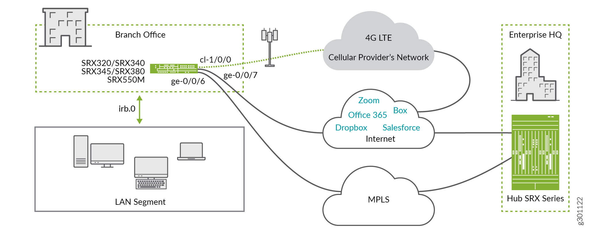
In the topology:
The LTE Mini-PIM is installed in slot 1 of the SRX Series device.
The SIM card is installed in slot 1 of the LTE Mini-PIM.
The primary MPLS link is connected to the interface ge-0/0/6.
The broadband Internet link is connected to the interface ge-0/0/7.
The interface cl-1/0/0 identifies the modem Mini-PIM.
The link over the cellular network terminates on interface dl0.0.
The wired ports ge-0/0/6 and ge-0/0/7 receive their IP address, network mask, and default gateway through DHCP.
The LTE interfaces (cl-1/0/0 and dl0.0) receive IP address, network mask, default gateway by the cellular service provider.
In this example, we are using two security zones untrust and trust configured on the SRX320 device. The separation of the interfaces into security zones enables the separation of traffic and mitigates the risks the corporate Intranet is exposed to. Security zones also let you achieve clear and simplified implementation of security policies. The untrust zone hosts interfaces that have access to the Internet. The internal interfaces in the corporate Intranet are in the trust zone. See Figure 2 and Table 1 to understand the interfaces, security zones, and security policy configuration.
Figure 2 shows the interfaces in each security zone.

Table 1 shows the desired behavior of the security policies for the traffic between the zones.
From Zone |
To Zone |
Security Policy Behavior to Allow Traffic |
|---|---|---|
Trust |
Trust |
Yes |
Untrust |
Untrust |
No |
Trust |
Untrust |
Yes |
Untrust |
Trust |
Trust-initiated only. Allow traffic initiated in the trust zone and the return traffic. |
Table 2 summarizes the VLAN information and the IP address information for the interfaces.
Interface |
VLAN |
IP Address |
Network Mask |
|---|---|---|---|
dl0.0 |
- |
DHCP |
- |
ge-0/0/6 |
DHCP |
255.255.255.0 |
|
ge-0/0/7 |
- |
DHCP |
- |
irb.0 |
3 |
192.168.1.1 |
255.255.255.0 |
Let’s consider the applications in Table 3. For illustrative purpose, lets assume that Office365, Salesforce and Zoom applications are business-critical, we’ll route them through the MPLS link predominantly. We are prioritizing these applications over the LTE link as well. The remaining applications will use broadband Internet access link. We are reserving LTE backup link for only business-critical applications. As a result, noncritical applications are inaccessible when the LTE connection is the only connection available.
Applications |
Primary Link |
Secondary Link |
Critical Application? |
|---|---|---|---|
Office365 |
MPLS |
Broadband Internet |
Yes |
Salesforce |
MPLS |
Broadband Internet |
Yes |
Zoom |
MPLS |
Broadband Internet |
Yes |
Slack |
Broadband Internet |
MPLS |
No |
GoToMeeting |
Broadband Internet |
MPLS |
No |
Dropbox |
Broadband Internet |
MPLS |
No |
Skype |
Broadband Internet |
MPLS |
No |
Youtube |
Broadband Internet |
MPLS |
No |
Configuration
Procedure
Step-by-Step Procedure
The steps in this configuration example are logically build from the lower layers to the upper layers.
Set the Access Point Name (APN) for the SIM in the modem (LTE-MPIM).
user@host>request modem wireless create-profile profile-id 10 access-point-name broadband cl-1/0/0 slot 1Create a common VLAN for the LAN segment of the network. In this example we use VLAN ID 3 and call it vlan-trust.
user@host#set vlans vlan-trust vlan-id 3 set vlans vlan-trust l3-interface irb.0Define AppQoS rules and application match criteria.
 set class-of-service application-traffic-control rule-sets critical_app_rs rule 1 match application-any
 set class-of-service application-traffic-control rule-sets critical_app_rs rule 1 then log
Create a security policy to allow traffic between the trust zone and untrust zone. Make sure to include the desired network segments and applications in the policy.
set security policies from-zone trust to-zone untrust policy allow-in-zone match source-address 192.168.1.0/24
 set security policies from-zone trust to-zone untrust policy allow-in-zone match destination-address any
 set security policies from-zone trust to-zone untrust policy allow-in-zone match application any
 set security policies from-zone trust to-zone untrust policy allow-in-zone then permit application-services application-traffic-control rule-set critical_app_rs
Create a security policy to allow traffic between devices in the trust zone. Make sure to include the desired network segments and applications in the policy.
set security policies from-zone trust to-zone trust policy allow-in-zone match source-address 192.168.1.0/24
 set security policies from-zone trust to-zone trust policy allow-in-zone match destination-address 192.168.1.0/24
 set security policies from-zone trust to-zone trust policy allow-in-zone match application any
 set security policies from-zone trust to-zone trust policy allow-in-zone then permit
Create a unique DHCP server group for the devices that are connected on the LAN segment.
set system services dhcp-local-server group jdhcp -group interface irb.0
Create a pool of IP addresses to be assigned to devices in the LAN segment. For this pool of IP addresses, specify the lowest and the highest IP address, the IP address for the DNS servers, and the IP address of the default gateway (
irb.0interface).The default gateway is usually the irb.0 interface.set access address-assignment pool junosDHCPPool family inet network 192.168.1.0/24 set access address-assignment pool junosDHCPPool family inet range junosRange low 192.168.1.10 set access address-assignment pool junosDHCPPool family inet range junosRange high 192.168.1.240 set access address-assignment pool junosDHCPPool family inet dhcp-attributes name-server 8.8.8.8 set access address-assignment pool junosDHCPPool family inet dhcp-attributes name-server 1.1.1.1 set access address-assignment pool junosDHCPPool family inet dhcp-attributes propagate-settings ge-0/0/7 set access address-assignment pool junosDHCPPool family inet dhcp-attributes router 192.168.1.1
Create source NAT to apply NAT to devices in the trust zone to the outer interface.
set security nat source rule-set trust-to-untrust from zone trust
set security nat source rule-set trust-to-untrust to zone untrust
set security nat source rule-set trust-to-untrust rule source-nat-rule match source-address 192.168.1.0/24
set security nat source rule-set trust-to-untrust rule r1 then source-nat interface
Configure the interface for the primary Internet link. Set the interface to obtain configuration over DHCP protocol.
set interfaces ge-0/0/7 unit 0 description "WAN Interface 1 - Primary"
set interfaces ge-0/0/7 unit 0 family inet dhcp vendor-id Juniper-srx320
Configure the LTE-MPIM interface. Ensure that the SIM slot, which contains the SIM card, is set to active.
set interfaces cl-1/0/0 description “WAN Interfaces 2 – Backup”
set interfaces cl-1/0/0 dialer-options pool 1 priority 100
set interfaces cl-1/0/0 act-sim 1
set interfaces cl-1/0/0 cellular-options sim 1 radio-access automatic
Configure the dialer interface.
set interfaces dl0 unit 0 family inet negotiate-address
set interfaces dl0 unit 0 family inet6 negotiate-address
set interfaces dl0 unit 0 dialer-options pool 1
set interfaces dl0 unit 0 dialer-options dial-string "*99#"
Configure the LAN interfaces ge-0/0/0, ge-0/0/1, and the other interfaces as switching interfaces in the trust VLAN. The trust VLAN effectively add the interfaces to the trust zone. We are showing configuration for one interface. Repeat the same steps to configure all LAN segment interfaces.
set interface ge-0/0/0 unit 0 family ethernet-switching vlan members vlan-trust
Allow the necessary protocols in the trust zone. This step ensures proper operation of the LAN segment of the network.
set security zones security-zone trust host-inbound-traffic system-services all
set security zones security-zone trust host-inbound-traffic protocols all
set security zones security-zone trust interfaces irb.0
Allow the necessary protocols in the untrust zone.
set security zones security-zone untrust screen untrust-screen
set security zones security-zone untrust interfaces ge-0/0/7.0 host-inbound-traffic system-services dhcp
set security zones security-zone untrust interfaces ge-0/0/7.0 host-inbound-traffic system-services tftp
set security zones security-zone untrust interfaces ge-0/0/7.0 host-inbound-traffic system-services netconf
 set security zones security-zone untrust interfaces ge-0/0/6.0 host-inbound-traffic system-services dhcp
set security zones security-zone untrust interfaces ge-0/0/6.0 host-inbound-traffic system-services tftp
set security zones security-zone untrust interfaces ge-0/0/6.0 host-inbound-traffic system-services netconf
set security zones security-zone untrust interfaces dl0.0 host-inbound-traffic system-services tftp
Create time-performance monitoring probes for each application and each link specified in Table 3.
In this step, we are setting probe type as
icmp-pingto the Office365 application. Office365 uses the MPLS link. This probe test probes the connectivity to the IP address 40.97.223.114, which is used by Office365. The probe test runs 5 times, 6 seconds apart. The expected thresholds that should not be violated are loss of 5 successive tests and/or return transmit time (RTT) of 300000 microseconds. The IP address of the gateway on interface ge-0/0/6 is 192.168.220.1set services rpm probe office365_rpm_primary test office365_test_primary probe-type icmp-ping set services rpm probe office365_rpm_primary test office365_test_primary target address 40.97.223.114 set services rpm probe office365_rpm_primary test office365_test_primary probe-count 5 set services rpm probe office365_rpm_primary test office365_test_primary probe-interval 6 set services rpm probe office365_rpm_primary test office365_test_primary thresholds successive-loss 5 set services rpm probe office365_rpm_primary test office365_test_primary rtt 300000 set services rpm probe office365_rpm_primary test office365_test_primary destination-interface ge-0/0/6.0 set services rpm probe office365_rpm_primary test office365_test_primary next-hop 192.168.220.1
Create the second probe for the same application. Be sure to use the secondary interface details for this application. The IP address of the default gateway on the broadband Internet link is 10.10.10.1.
set services rpm probe office365_rpm_secondary test office365_test_secondary probe-type icmp-ping
set services rpm probe office365_rpm_secondary test office365_test_secondary target address 40.97.223.114
set services rpm probe office365_rpm_secondary test office365_test_secondary probe-count 5
set services rpm probe office365_rpm_secondary test office365_test_secondary probe-interval 6
set services rpm probe office365_rpm_secondary test office365_test_secondary thresholds successive-loss 5
set services rpm probe office365_rpm_secondary test office365_test_secondary rtt 300000
set services rpm probe office365_rpm_secondary test office365_test_secondary destination-interface ge-0/0/7.0
set services rpm probe office365_rpm_secondary test office365_test_secondary next-hop 10.10.10.1
Create two probes for the Skype application.
In this step, we are setting a shorter probe interval of 1 second, and a shorter RTT of 60000 microseconds. This configuration reflects the higher link guarantees for the application. Note that the interface for the primary probe is ge-0/0/7 and the IP address to be probed is different, compared to Office365. The IP addresses used in this step are the target addresses that we use for our probes. That is, each of the target addresses belongs to the application, for which we’ve created the probe.
set services rpm probe skype_rpm_primary test skype_test_primary probe-type icmp-ping
set services rpm probe skype_rpm_primary test skype_test_primary target address 13.107.8.2
set services rpm probe skype_rpm_primary test skype_test_primary probe-count 5
set services rpm probe skype_rpm_primary test skype_test_primary probe-interval 1
set services rpm probe skype_rpm_primary test skype_test_primary thresholds successive-loss 5
set services rpm probe skype_rpm_primary test skype_test_primary rtt 60000
set services rpm probe skype_rpm_primary test skype_test_primary destination-interface ge-0/0/7.0
set services rpm probe skype_rpm_primary test skype_test_primary next-hop 10.10.10.1
set services rpm probe skype_rpm_secondary test skype_test_secondary probe-type icmp-ping
set services rpm probe skype_rpm_secondary test skype_test_secondary target address 13.107.8.2
set services rpm probe skype_rpm_secondary test skype_test_secondary probe-count 5
set services rpm probe skype_rpm_secondary test skype_test_secondary probe-interval 1
set services rpm probe skype_rpm_secondary test skype_test_secondary thresholds successive-loss 5
set services rpm probe skype_rpm_secondary test skype_test_secondary rtt 60000
set services rpm probe skype_rpm_secondary test skype_test_secondary destination-interface ge-0/0/6.0
set services rpm probe skype_rpm_secondary test skype_test_secondary next-hop 192.168.220.1
Configure the probes for the remaining applications using the same pattern.
set services rpm probe salesforce_rpm_primary test salesforce_test_primary probe-type icmp-ping
set services rpm probe salesforce_rpm_primary test salesforce_test_primary target address 96.43.144.26
set services rpm probe salesforce_rpm_primary test salesforce_test_primary probe-count 5
set services rpm probe salesforce_rpm_primary test salesforce_test_primary probe-interval 6
set services rpm probe salesforce_rpm_primary test salesforce_test_primary thresholds successive-loss 5
set services rpm probe salesforce_rpm_primary test salesforce_test_primary rtt 300000
set services rpm probe salesforce_rpm_primary test salesforce_test_primary destination-interface ge-0/0/6.0
set services rpm probe salesforce_rpm_primary test salesforce_test_primary next-hop 192.168.220.1
set services rpm probe salesforce_rpm_secondary test salesforce_test_secondary probe-type icmp-ping
set services rpm probe salesforce_rpm_secondary test salesforce_test_secondary target address 96.43.144.26
set services rpm probe salesforce_rpm_secondary test salesforce_test_secondary probe-count 5
set services rpm probe salesforce_rpm_secondary test salesforce_test_secondary probe-interval 6
set services rpm probe salesforce_rpm_secondary test salesforce_test_secondary thresholds successive-loss 5
set services rpm probe salesforce_rpm_secondary test salesforce_test_secondary rtt 300000
set services rpm probe salesforce_rpm_secondary test salesforce_test_secondary destination-interface ge-0/0/7.0
set services rpm probe salesforce_rpm_secondary test salesforce_test_secondary next-hop 10.10.10.1
set services rpm probe dropbox_rpm_primary test dropbox_test_primary probe-type icmp-ping
set services rpm probe dropbox_rpm_primary test dropbox_test_primary target address 162.125.248.1
set services rpm probe dropbox_rpm_primary test dropbox_test_primary probe-count 5
set services rpm probe dropbox_rpm_primary test dropbox_test_primary probe-interval 1
set services rpm probe dropbox_rpm_primary test dropbox_test_primary thresholds successive-loss 5
set services rpm probe dropbox_rpm_primary test dropbox_test_primary rtt 200000
set services rpm probe dropbox_rpm_primary test dropbox_test_primary destination-interface ge-0/0/7.0
set services rpm probe dropbox_rpm_primary test dropbox_test_primary next-hop 10.10.10.1
set services rpm probe dropbox_rpm_secondary test dropbox_test_secondary probe-type icmp-ping
set services rpm probe dropbox_rpm_secondary test dropbox_test_secondary target address 162.125.248.1
set services rpm probe dropbox_rpm_secondary test dropbox_test_secondary probe-count 5
set services rpm probe dropbox_rpm_secondary test dropbox_test_secondary probe-interval 1
set services rpm probe dropbox_rpm_secondary test dropbox_test_secondary thresholds successive-loss 5
set services rpm probe dropbox_rpm_secondary test dropbox_test_secondary rtt 200000
set services rpm probe dropbox_rpm_secondary test dropbox_test_secondary destination-interface ge-0/0/6.0
set services rpm probe dropbox_rpm_secondary test dropbox_test_secondary next-hop 192.168.220.1
set services rpm probe zoom_rpm_primary test zoom_test_primary probe-type icmp-ping
set services rpm probe zoom_rpm_primary test zoom_test_primary target address 3.80.20.128
set services rpm probe zoom_rpm_primary test zoom_test_primary probe-count 5
set services rpm probe zoom_rpm_primary test zoom_test_primary probe-interval 1
set services rpm probe zoom_rpm_primary test zoom_test_primary thresholds successive-loss 5
set services rpm probe zoom_rpm_primary test zoom_test_primary rtt 60000
set services rpm probe zoom_rpm_primary test zoom_test_primary destination-interface ge-0/0/6.0
set services rpm probe zoom_rpm_primary test zoom_test_primary next-hop 192.168.220.1
set services rpm probe zoom_rpm_secondary test zoom_test_secondary probe-type icmp-ping
set services rpm probe zoom_rpm_secondary test zoom_test_secondary target address 3.80.20.128
set services rpm probe zoom_rpm_secondary test zoom_test_secondary probe-count 5
set services rpm probe zoom_rpm_secondary test zoom_test_secondary probe-interval 1
set services rpm probe zoom_rpm_secondary test zoom_test_secondary thresholds successive-loss 5
set services rpm probe zoom_rpm_secondary test zoom_test_secondary rtt 60000
set services rpm probe zoom_rpm_secondary test zoom_test_secondary destination-interface ge-0/0/7.0
set services rpm probe zoom_rpm_secondary test zoom_test_secondary next-hop 10.10.10.1
set services rpm probe gotomeeting_rpm_primary test gotomeeting_test_primary probe-type icmp-ping
set services rpm probe gotomeeting_rpm_primary test gotomeeting_test_primary target address 216.115.208.241
set services rpm probe gotomeeting_rpm_primary test gotomeeting_test_primary probe-count 5
set services rpm probe gotomeeting_rpm_primary test gotomeeting_test_primary probe-interval 1
set services rpm probe gotomeeting_rpm_primary test gotomeeting_test_primary thresholds successive-loss 5
set services rpm probe gotomeeting_rpm_primary test gotomeeting_test_primary rtt 60000
set services rpm probe gotomeeting_rpm_primary test gotomeeting_test_primary destination-interface ge-0/0/7.0
set services rpm probe gotomeeting_rpm_primary test gotomeeting_test_primary next-hop 10.10.10.1
set services rpm probe gotomeeting_rpm_secondary test gotomeeting_test_secondary probe-type icmp-ping
set services rpm probe gotomeeting_rpm_secondary test gotomeeting_test_secondary target address 216.115.208.241
set services rpm probe gotomeeting_rpm_secondary test gotomeeting_test_secondary probe-count 5
set services rpm probe gotomeeting_rpm_secondary test gotomeeting_test_secondary probe-interval 1
set services rpm probe gotomeeting_rpm_secondary test gotomeeting_test_secondary thresholds successive-loss 5
set services rpm probe gotomeeting_rpm_secondary test gotomeeting_test_secondary rtt 60000
set services rpm probe gotomeeting_rpm_secondary test gotomeeting_test_secondary destination-interface ge-0/0/6.0
set services rpm probe gotomeeting_rpm_secondary test gotomeeting_test_secondary next-hop 192.168.220.1
set services rpm probe youtube_rpm_primary test youtube_test_primary probe-type http-get
set services rpm probe youtube_rpm_primary test youtube_test_primary target url https://youtube.com
set services rpm probe youtube_rpm_primary test youtube_test_primary probe-count 5
set services rpm probe youtube_rpm_primary test youtube_test_primary probe-interval 10
set services rpm probe youtube_rpm_primary test youtube_test_primary thresholds successive-loss 5
set services rpm probe youtube_rpm_primary test youtube_test_primary rtt 150000
set services rpm probe youtube_rpm_primary test youtube_test_primary destination-interface ge-0/0/7.0
set services rpm probe youtube_rpm_primary test youtube_test_primary next-hop 10.10.10.1
set services rpm probe youtube_rpm_secondary test youtube_test_secondary probe-type http-get
set services rpm probe youtube_rpm_secondary test youtube_test_secondary target url https://youtube.com
set services rpm probe youtube_rpm_secondary test youtube_test_secondary probe-count 5
set services rpm probe youtube_rpm_secondary test youtube_test_secondary probe-interval 10
set services rpm probe youtube_rpm_secondary test youtube_test_secondary thresholds successive-loss 5
set services rpm probe youtube_rpm_secondary test youtube_test_secondary rtt 150000
set services rpm probe youtube_rpm_secondary test youtube_test_secondary destination-interface ge-0/0/6.0
set services rpm probe youtube_rpm_secondary test youtube_test_secondary next-hop 192.168.220.1
set services rpm probe slack_rpm_primary test slack_test_primary probe-type icmp-ping
set services rpm probe slack_rpm_primary test slack_test_primary target address 216.115.208.241
set services rpm probe slack_rpm_primary test slack_test_primary probe-count 5
set services rpm probe slack_rpm_primary test slack_test_primary probe-interval 1
set services rpm probe slack_rpm_primary test slack_test_primary thresholds successive-loss 5
set services rpm probe slack_rpm_primary test slack_test_primary rtt 60000
set services rpm probe slack_rpm_primary test slack_test_primary destination-interface ge-0/0/7.0
set services rpm probe slack_rpm_primary test slack_test_primary next-hop 10.10.10.1
set services rpm probe slack_rpm_secondary test slack_test_secondary probe-type icmp-ping
set services rpm probe slack_rpm_secondary test slack_test_secondary target address 216.115.208.241
set services rpm probe slack_rpm_secondary test slack_test_secondary probe-count 5
set services rpm probe slack_rpm_secondary test slack_test_secondary probe-interval 1
set services rpm probe slack_rpm_secondary test slack_test_secondary thresholds successive-loss 5
set services rpm probe slack_rpm_secondary test slack_test_secondary rtt 60000
set services rpm probe slack_rpm_secondary test slack_test_secondary destination-interface ge-0/0/6.0
set services rpm probe slack_rpm_secondary test slack_test_secondary next-hop 192.168.220.1
Create a routing instance for each application. Ensure that the route over the primary link for that application has a lower preference value, compared to the other links. Lower preference value makes the route more preferred. Ensure that the business-critical applications use the LTE backup interface.
In this step, we are configuring the routing instance for the Office365 application. The primary link is the MPLS link. Setting a preference value of 10 to the gateway of this link makes it the most preferred route. Preference value of 20 for the gateway of the broadband Internet link makes it the second best preferred option. The LTE backup link has a preference value of 30 and is the least preferred option.
set routing-instances office365_RInstance instance-type forwarding
set routing-instances office365_RInstance routing-options static route 0/0 qualified-next-hop 192.168.220.1 preference 10
set routing-instances office365_RInstance routing-options static route 0/0 qualified-next-hop 10.10.10.1  preference 20
set routing-instances office365_RInstance routing-options static route 0/0 qualified-next-hop dl0.0
set routing-instances office365_RInstance routing-options static route 0/0 preference 30
Configure the routing instances for the remaining applications using the same pattern as in the previous step.
set routing-instances skype_RInstance instance-type forwarding
set routing-instances skype_RInstance routing-options static route 0/0 qualified-next-hop 10.10.10.1 preference 10
set routing-instances skype_RInstance routing-options static route 0/0 qualified-next-hop 192.168.220.1 preference 20
set routing-instances salesforce_RInstance instance-type forwarding
set routing-instances salesforce_RInstance routing-options static route 0/0 qualified-next-hop 192.168.220.1 preference 10
set routing-instances salesforce_RInstance routing-options static route 0/0 qualified-next-hop 10.10.10.1 preference 20
set routing-instances salesforce_RInstance routing-options static route 0/0 qualified-next-hop dl0.0 preference 30
set routing-instances dropbox_RInstance instance-type forwarding
set routing-instances dropbox_RInstance routing-options static route 0/0 qualified-next-hop 10.10.10.1 preference 10
set routing-instances dropbox_RInstance routing-options static route 0/0 qualified-next-hop 192.168.220.1 preference 20
set routing-instances slack_RInstance instance-type forwarding
set routing-instances slack_RInstance routing-options static route 0/0 qualified-next-hop 10.10.10.1 preference 10
set routing-instances slack_RInstance routing-options static route 0/0 qualified-next-hop 192.168.220.1 preference 20
set routing-instances zoom_RInstance instance-type forwarding
set routing-instances zoom_RInstance routing-options static route 0/0 qualified-next-hop 192.168.220.1 preference 10
set routing-instances zoom_RInstance routing-options static route 0/0 qualified-next-hop 10.10.10.1 preference 20
set routing-instances zoom_RInstance routing-options static route 0/0 qualified-next-hop dl0.0 preference 30
set routing-instances gotomeeting_RInstance instance-type forwarding
set routing-instances gotomeeting_RInstance routing-options static route 0/0 qualified-next-hop 10.10.10.1 preference 10
set routing-instances gotomeeting_RInstance routing-options static route 0/0 qualified-next-hop 192.168.220.1 preference 20
set routing-instances youtube_RInstance instance-type forwarding
set routing-instances youtube_RInstance routing-options static route 0/0 qualified-next-hop 10.10.10.1 preference 10
set routing-instances youtube_RInstance routing-options static route 0/0 qualified-next-hop 192.168.220.1 preference 20
Configure IP monitoring policies for all applications. The goal of the policies is to change the metric of routes that are created in the routing instances from the previous step. The policies are created on a per-probe basis.
In this step, we are creating an IP monitoring policy for office365 application. We have configured two probes and therefore created two policies—one for each probe. When the probed link deviates from the allowed thresholds, the policy changes the preference of the routes in order to reroute the application traffic over the other link . The policy decreases the metric for the second best link to 2.
Example: When the probe identifies that the primary link (MPLS) for Office35 does not meet the requirements for RTT and packet loss, the policy allows the gateway for the broadband Internet link to have a metric of 2. Note that the policy changes the metric for the second best route.
set services ip-monitoring policy office365_ipm_primary match rpm-probe office365_rpm_primary
set services ip-monitoring policy office365_ipm_primary then preferred-route routing-instances office365_RInstance route 0/0 next-hop 10.10.10.1
set services ip-monitoring policy office365_ipm_primary then preferred-route routing-instances office365_RInstance route 0/0 preferred-metric 2
Configure the IP monitoring policy for the secondary probe for Office365. The next-hop address is the primary MPLS link.
set services ip-monitoring policy office365_ipm_secondary match rpm-probe office365_rpm_ secondary
set services ip-monitoring policy office365_ipm_ secondary then preferred-route routing-instances office365_RInstance route 0/0 next-hop 192.168.220.1
set services ip-monitoring policy office365_ipm_ secondary then preferred-route routing-instances office365_RInstance route 0/0 preferred-metric 2
Configure IP monitoring policy for the remaining applications following the similar pattern as done in previous two steps.
set services ip-monitoring policy skype_ipm_primary match rpm-probe skype_rpm_primary
set services ip-monitoring policy skype_ipm_primary then preferred-route routing-instances skype_RInstance route 0/0 next-hop 192.168.220.1
set services ip-monitoring policy skype_ipm_primary then preferred-route routing-instances skype_RInstance route 0/0 preferred-metric 2
set services ip-monitoring policy skype_ipm_secondary match rpm-probe skype_rpm_ secondary
set services ip-monitoring policy skype_ipm_ secondary then preferred-route routing-instances skype_RInstance route 0/0 next-hop 10.10.10.1
set services ip-monitoring policy skype_ipm_ secondary then preferred-route routing-instances skype_RInstance route 0/0 preferred-metric 2
set services ip-monitoring policy salesforce_ipm_primary match rpm-probe salesforce_rpm_primary
set services ip-monitoring policy salesforce_ipm_primary then preferred-route routing-instances salesforce_RInstance route 0/0 next-hop 10.10.10.1
set services ip-monitoring policy salesforce_ipm_primary then preferred-route routing-instances salesforce_RInstance route 0/0 preferred-metric 2
set services ip-monitoring policy salesforce_ipm_secondary match rpm-probe salesforce_rpm_ secondary
set services ip-monitoring policy salesforce_ipm_ secondary then preferred-route routing-instances salesforce_RInstance route 0/0 next-hop 192.168.220.1
set services ip-monitoring policy salesforce_ipm_ secondary then preferred-route routing-instances salesforce_RInstance route 0/0 preferred-metric 2
set services ip-monitoring policy dropbox_ipm_primary match rpm-probe dropbox_rpm_primary
set services ip-monitoring policy dropbox_ipm_primary then preferred-route routing-instances dropbox_RInstance route 0/0 next-hop 192.168.220.1
set services ip-monitoring policy dropbox_ipm_primary then preferred-route routing-instances dropbox_RInstance route 0/0 preferred-metric 2
set services ip-monitoring policy dropbox_ipm_secondary match rpm-probe dropbox_rpm_ secondary
set services ip-monitoring policy dropbox_ipm_ secondary then preferred-route routing-instances dropbox_RInstance route 0/0 next-hop 10.10.10.1
set services ip-monitoring policy dropbox_ipm_ secondary then preferred-route routing-instances dropbox_RInstance route 0/0 preferred-metric 2
set services ip-monitoring policy slack_ipm_primary match rpm-probe slack_rpm_primary
set services ip-monitoring policy slack_ipm_primary then preferred-route routing-instances slack_RInstance route 0/0 next-hop 192.168.220.1
set services ip-monitoring policy slack_ipm_primary then preferred-route routing-instances slack_RInstance route 0/0 preferred-metric 2
set services ip-monitoring policy slack_ipm_secondary match rpm-probe slack_rpm_ secondary
set services ip-monitoring policy slack_ipm_ secondary then preferred-route routing-instances slack_RInstance route 0/0 next-hop 10.10.10.1
set services ip-monitoring policy slack_ipm_ secondary then preferred-route routing-instances slack_RInstance route 0/0 preferred-metric 2
set services ip-monitoring policy zoom_ipm_primary match rpm-probe zoom_rpm_primary
set services ip-monitoring policy zoom_ipm_primary then preferred-route routing-instances zoom_RInstance route 0/0 next-hop 10.10.10.1
set services ip-monitoring policy zoom_ipm_primary then preferred-route routing-instances zoom_RInstance route 0/0 preferred-metric 2
set services ip-monitoring policy zoom_ipm_secondary match rpm-probe zoom_rpm_ secondary
set services ip-monitoring policy zoom_ipm_ secondary then preferred-route routing-instances zoom_RInstance route 0/0 next-hop 192.168.220.1
set services ip-monitoring policy zoom_ipm_ secondary then preferred-route routing-instances zoom_RInstance route 0/0 preferred-metric 2
set services ip-monitoring policy gotomeeting_ipm_primary match rpm-probe gotomeeting_rpm_primary
set services ip-monitoring policy gotomeeting_ipm_primary then preferred-route routing-instances gotomeeting_RInstance route 0/0 next-hop 192.168.220.1
set services ip-monitoring policy gotomeeting_ipm_primary then preferred-route routing-instances gotomeeting_RInstance route 0/0 preferred-metric 2
set services ip-monitoring policy gotomeeting_ipm_secondary match rpm-probe gotomeeting_rpm_ secondary
set services ip-monitoring policy gotomeeting_ipm_ secondary then preferred-route routing-instances gotomeeting_RInstance route 0/0 next-hop 10.10.10.1
set services ip-monitoring policy gotomeeting_ipm_ secondary then preferred-route routing-instances gotomeeting_RInstance route 0/ preferred-metric 2
set services ip-monitoring policy youtube_ipm_primary match rpm-probe youtube_rpm_primary
set services ip-monitoring policy youtube_ipm_primary then preferred-route routing-instances youtube_RInstance route 0/0 next-hop 192.168.220.1
set services ip-monitoring policy youtube_ipm_primary then preferred-route routing-instances youtube_RInstance route 0/0 preferred-metric 2
set services ip-monitoring policy youtube_ipm_secondary match rpm-probe youtube_rpm_ secondary
set services ip-monitoring policy youtube_ipm_ secondary then preferred-route routing-instances youtube_RInstance route 0/0 next-hop 10.10.10.1
set services ip-monitoring policy youtube_ipm_ secondary then preferred-route routing-instances youtube_RInstance route 0/0 preferred-metric 2
Configure an advanced policy-based routing (APBR) profile that matches all eight applications in scope and redirects the traffic to the respective routing instance for that application. The profile is divided into rules. Each rule covers one application and one routing instance.
In this step, the rule
office365_rulematches all traffic for applicationjunos:OFFICE365-CREATE-CONVERSATION” and redirects traffic to routing instanceoffice365_RInstance.set security advance-policy-based-routing tunables max-route-change 0 set security advance-policy-based-routing profile apbr_profile rule office365_rule match dynamic-application junos:OFFICE365-CREATE-CONVERSATION set security advance-policy-based-routing profile apbr_profile rule office365_rule then routing-instance office365_RInstance set security advance-policy-based-routing profile apbr_profile rule skype_rule match dynamic-application junos: SKYPE set security advance-policy-based-routing profile apbr_profile rule skype_rule then routing-instance skype_RInstance set security advance-policy-based-routing profile apbr_profile rule salesforce_rule match dynamic-application junos:SALESFORCE set security advance-policy-based-routing profile apbr_profile rule salesforce_rule then routing-instance salesforce_RInstance set security advance-policy-based-routing profile apbr_profile rule dropbox_rule match dynamic-application junos: DROPBOX set security advance-policy-based-routing profile apbr_profile rule dropbox_rule then routing-instance dropbox_RInstance set security advance-policy-based-routing profile apbr_profile rule slack_rule match dynamic-application junos:SLACK set security advance-policy-based-routing profile apbr_profile rule slack_rule then routing-instance slack_RInstance set security advance-policy-based-routing profile apbr_profile rule zoom_rule match dynamic-application junos:ZOOM set security advance-policy-based-routing profile apbr_profile rule zoom_rule then routing-instance zoom_RInstance set security advance-policy-based-routing profile apbr_profile rule gotomeeting_rule match dynamic-application junos: GOTOMEETING set security advance-policy-based-routing profile apbr_profile rule gotomeeting_rule then routing-instance gotomeeting_RInstance set security advance-policy-based-routing profile apbr_profile rule youtube_rule match dynamic-application junos:YOUTUBE set security advance-policy-based-routing profile apbr_profile rule youtube_rule then routing-instance youtube_RInstance set
In this step, we are not allowing mid-session path changes for the ongoing sessions to avoid any impact on the application continuity. This is achieved by setting the
max-route-changeparameter to 0.Configure a protocol-independent group of routing tables. The group imports the routing tables of the dedicated instances to the main routing table.
set routing-options interface-routes rib-group inet apbr_group
set routing-options rib-groups apbr_group import-rib inet.0
set routing-options rib-groups apbr_group import-rib office365_RInstance.inet.0
set routing-options rib-groups apbr_group import-rib skype_RInstance.inet.0
set routing-options rib-groups apbr_group import-rib salesforce_RInstance.inet.0
set routing-options rib-groups apbr_group import-rib dropbox_RInstance.inet.0
set routing-options rib-groups apbr_group import-rib slack_RInstance.inet.0
set routing-options rib-groups apbr_group import-rib zoom_RInstance.inet.0
set routing-options rib-groups apbr_group import-rib gotomeeting_RInstance.inet.0
set routing-options rib-groups apbr_group import-rib youtube_RInstance.inet.0
Add the newly created profile
apbr_profileto the security zone trust. This configuration applies the profile to traffic in the trust zone.set security zones security-zone trust advance-policy-based-routing-profile apbr_profile
Commit the configuration.
commit
Validation
To confirm that the configuration is working properly, perform the following tasks:
- Verify Detection of Mini-PIM Modules by Junos OS
- Verify the Firmware Version of the Mini-PIM
- Verify APBR Rule Effectiveness
Verify Detection of Mini-PIM Modules by Junos OS
Purpose
Verify that the Junos OS is detecting Mini-PIM modules.
Action
From operational mode:
user@host> show chassis hardware
Hardware inventory:
Item             Version  Part number  Serial number     Description
Chassis                                CX0916AF0004      SRX320-POE
Routing Engine   REV 0x05 650-065041   CX0916AF0004      RE-SRX320-POE
FPC 0                                                    FPC
  PIC 0                                                  6xGE,2xGE SFP Base PIC
FPC 1            REV 02   650-073958   AH06074206        FPC
  PIC 0                                                  LTE for AE
Power Supply 0
Meaning
The device displays the Mini-PIM module LTE for
AE in the output.
Verify the Firmware Version of the Mini-PIM
Purpose
Check the firmware version of the Mini-PIM.
Action
From operational mode:
user@host> show system firmware
Part             Type              Tag Current       Available             Status
                                       version       version
FPC 1
PIC 0            MLTE_FW           1   17.1.80         0                     OK
Routing Engine 0 RE BIOS           0   3.0             3.6                   OK
Routing Engine 0 RE BIOS Backup    1   3.0             3.6                   OK
Meaning
The output shows the firmware version of the Mini-PIM as 17.1.80. Update the firmware if required. See Firmware Upgrade on the LTE Mini-Physical Interface Module.
Verify APBR Rule Effectiveness
Purpose
Verify the traffic handling details after applying the APBR rule.
Action
From operational mode:
user@host> show security advance-policy-based-routing statistics
Advance Profile Based Routing statistics:
  Sessions Processed                        5611
  App rule hit on cache hit                 1
  App rule hit on HTTP Proxy/ALG            0
  Midstream disabled rule hit on cache hit  0
  URL cat rule hit on cache hit             0
  DSCP rule hit on first packet             0
  App and DSCP hit on first packet          0
  App rule hit midstream                    0
  Midstream disabled rule hit midstream     0
  URL cat rule hit midstream                0
  App and DSCP rule hit midstream           0
  DSCP rule hit midstream                   0
  Route changed on cache hits               1
  Route changed on HTTP Proxy/ALG           0
  Route changed midstream                   0
  Zone mismatch                             0
  Drop on zone mismatch                     0
  Next hop not found                        0
  Application services bypass               0
Meaning
The output displays details about the sessions processed
for the application-based routing rule, the number of times the application
traffic matches the APBR profile (rule hit) and number
of time APBR is applied for the session (Route change).