QFX Series MC-LAG Fabric Upgrade Procedure
About This Network Configuration Example
This network configuration example (NCE) shows how to manually upgrade an MC-LAG pair of QFX series devices. This process minimizes service disruption and has minimal impact on data center workloads.
See Also
Use Case Overview
To eliminate the access switch as a single point of failure in a data center environment, multichassis link aggregation groups (MC-LAGs) enable a client device to form a logical LAG interface between two MC-LAG peers. An MC-LAG provides redundancy and load balancing between the two MC-LAG peers, multihoming support, and a loop-free Layer 2 network without running STP. This example uses a basic MC-LAG configuration, but you can use this process for many different use cases.
This example does not cover how to perform a non-stop software upgrade (NSSU).
Technical Overview
Manually upgrading MC-LAG peers is similar to an NSSU. The manual upgrade process uses a high-availability design to systematically remove one device from service in order to perform the upgrade and then reboot. When servers are dual-homed to each MC-LAG peer, the network can handle the removal of one of the MC-LAG peers during the upgrade window. There’s a reduction of overall network bandwidth during the process, but the network remains available.
The MC-LAG is in active-active state and uses the ICCP protocol to keep the device state synchronized between the members of the MC-LAG. While one peer handles the traffic, the other peer is taken offline to upgrade the software.
Figure 1 illustrates a basic MC-LAG topology.
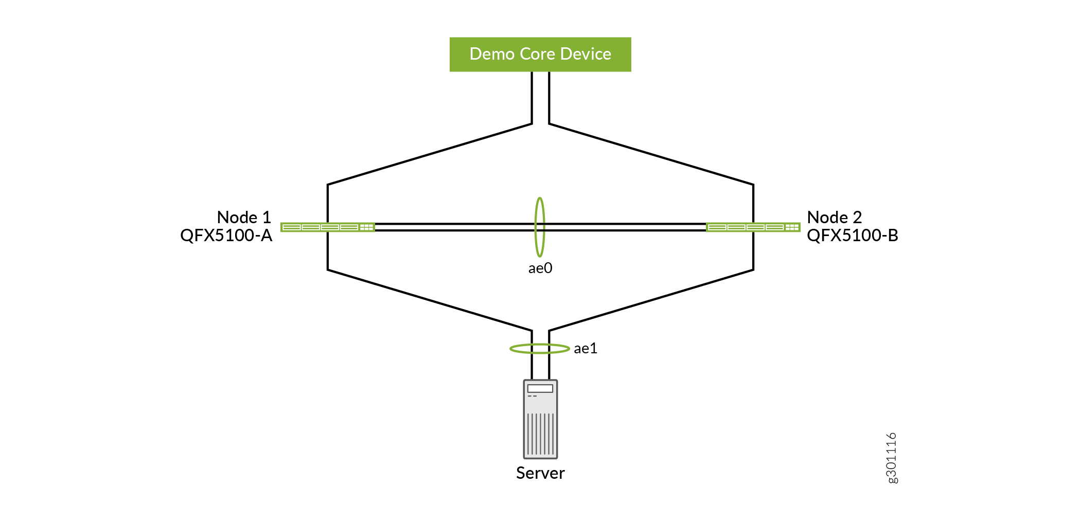
Here’s the sequence of events that occur during an upgrade between two MC-LAG peers (Node 1 and Node 2):
All traffic is shifted from Node 1 to Node 2.
Node 1 is no longer handling traffic, so the MC-LAG is no longer operational.
Software is installed on Node 1 and then reboots.
Node 1 comes online, and all traffic is shifted from Node 2 to Node 1.
Software is installed on Node 2 and then reboots.
When Node 2 is online, the MC-LAG interfaces are re-enabled between the Node 1 and Node 2.
How to Perform a QFX Series MC-LAG Fabric Upgrade
- Requirements
- Overview
- QFX Series MC-LAG Fabric Upgrade Configuration
- Upgrade the QFX Series MC-LAG Fabric
- Conclusion
- Device Configuration Details
Requirements
This example uses the following hardware and software components:
Two QFX5100 devices running Junos OS Release 18.2R3-S3
Junos OS Release 18.4R3.3
A test server running Ubuntu Linux 16.04
Overview
To ensure a minimum of downtime, upgrading between software releases requires a sequence of steps coordinated among all of the network elements This topology uses servers with redundant connections to the MC-LAG to achieve high-availability during the switch over between MC-LAG peers.
To upgrade the fabric to a new version of Junos OS with minimal traffic disruption, you need to disable the MC-LAG and upgrade the MC-LAG peers as standalone units. After the software has been upgraded on both MC-LAG peers, you will re-connect them and re-establish the MC-LAG.
QFX Series MC-LAG Fabric Upgrade Configuration
Prepare for the Upgrade
Step-by-Step Procedure
Use this procedure to upgrade both peers of a MC-LAG fabric consisting of QFX5100 switches to the same Junos OS Release version. We strongly recommend that both members of the MC-LAG are the same platform.
This configuration example shows how to manually upgrade MC-LAG peers from Junos OS Release 18.2R3-S3 to Junos OS Release 18.4R3.3.
Verify that the MC-LAG state is operational between both MC-LAG peers by checking the MC-LAG parameters.
user@QFX5100-A> show interfaces mc-ae Member Link : ae1 Current State Machine's State: mcae active state Local Status : active Local State : up Peer Status : active Peer State : up Logical Interface : ae1.0 Topology Type : bridge Local State : up Peer State : up Peer Ip/MCP/State : 10.3.3.1 ae0.0 upuser@QFX5100-A> show iccp Redundancy Group Information for peer 10.3.3.1 TCP Connection : Established Liveliness Detection : Up Backup liveness peer status: Up Redundancy Group ID Status 1 Up Client Application: lacpd Redundancy Group IDs Joined: 1 Client Application: l2ald_iccpd_client Redundancy Group IDs Joined: 1user@QFX5100-A> show lacp interfaces ae0 Aggregated interface: ae0 LACP state: Role Exp Def Dist Col Syn Aggr Timeout Activity xe-0/0/8 Actor No No Yes Yes Yes Yes Fast Active xe-0/0/8 Partner No No Yes Yes Yes Yes Fast Active xe-0/0/9 Actor No No Yes Yes Yes Yes Fast Active xe-0/0/9 Partner No No Yes Yes Yes Yes Fast Active LACP protocol: Receive State Transmit State Mux State xe-0/0/8 Current Fast periodic Collecting distributing xe-0/0/9 Current Fast periodic Collecting distributinguser@QFX5100-A> show lacp interfaces ae1 Aggregated interface: ae1 LACP state: Role Exp Def Dist Col Syn Aggr Timeout Activity xe-0/0/10 Actor No No Yes Yes Yes Yes Fast Active xe-0/0/10 Partner No No Yes Yes Yes Yes Fast Active LACP protocol: Receive State Transmit State Mux State xe-0/0/10 Current Fast periodic Collecting distributing
Upgrade the QFX Series MC-LAG Fabric
Procedure
Step-by-Step Procedure
Copy the new Junos OS software image to the
/var/tmpdirectories on both peers.Copying the software on both MC-LAG peers stages the software for the upgrade procedure. The copy operation takes some time to complete while it transfers the Junos OS software images from the server to the MC-LAG peers.
user@QFX5100-A> file copy http://server.juniper.net/volume/download/docroot/software/junos/18.4R3.3/jinstall-host-qfx-5-18.4R3.3-signed.tgz /var/tmp/ user@QFX5100-B> file copy http://server.juniper.net/volume/download/docroot/software/junos/18.4R3.3/jinstall-host-qfx-5-18.4R3.3-signed.tgz /var/tmp/
Disable the server-facing interfaces on QFX5100-A to minimize disruption during the switch over to QFX5100-B.
user@QFX5100-A# set interfaces xe-0/1/10 disable user@QFX5100-A# commit and-quit
Figure 3: Disabling the Server-Facing Interface on QFX5100-A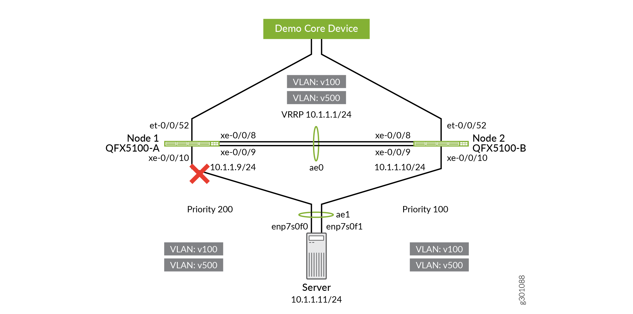
Disable the uplink interfaces on QFX5100-A.
user@QFX5100-A# set interfaces et-0/0/52 disable user@QFX5100-A# commit and-quit
Figure 4: Disabling the Uplink Interface on QFX5100-A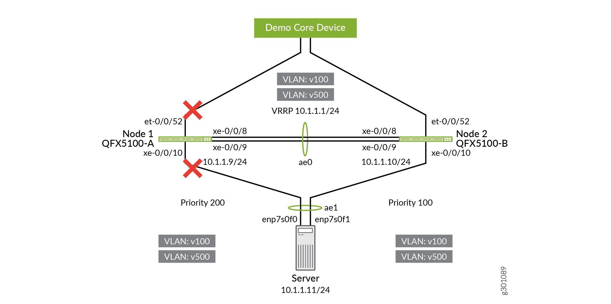
Disable the interfaces between the QFX5100-A and QFX5100-B.
This breaks up the MC-LAG.
user@QFX5100-A# set interfaces xe-0/0/8 disable user@QFX5100-A# set interfaces xe-0/0/9 disable user@QFX5100-A# commit and-quit
user@QFX5100-B# set interfaces xe-0/0/8 disable user@QFX5100-B# set interfaces xe-0/0/9 disable user@QFX5100-B# commit and-quit
Figure 5: Disabling Interfaces Between QFX5100-A and QFX5100-B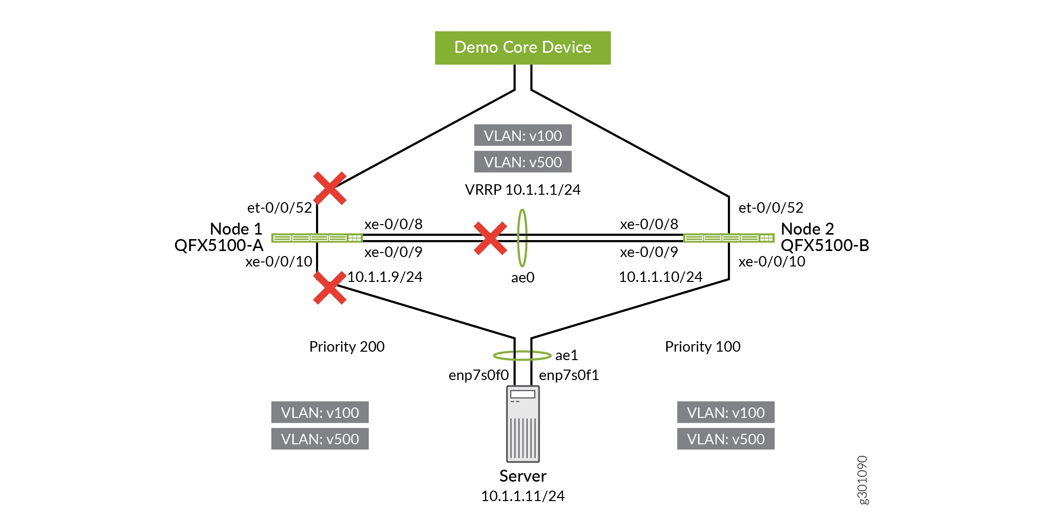
Upgrade QFX5100-A.
user@QFX5100-A> request system software add /var/tmp/jinstall-host-qfx-5-18.4R3.3-signed.tgz reboot
Figure 6: Upgrading QFX5100-A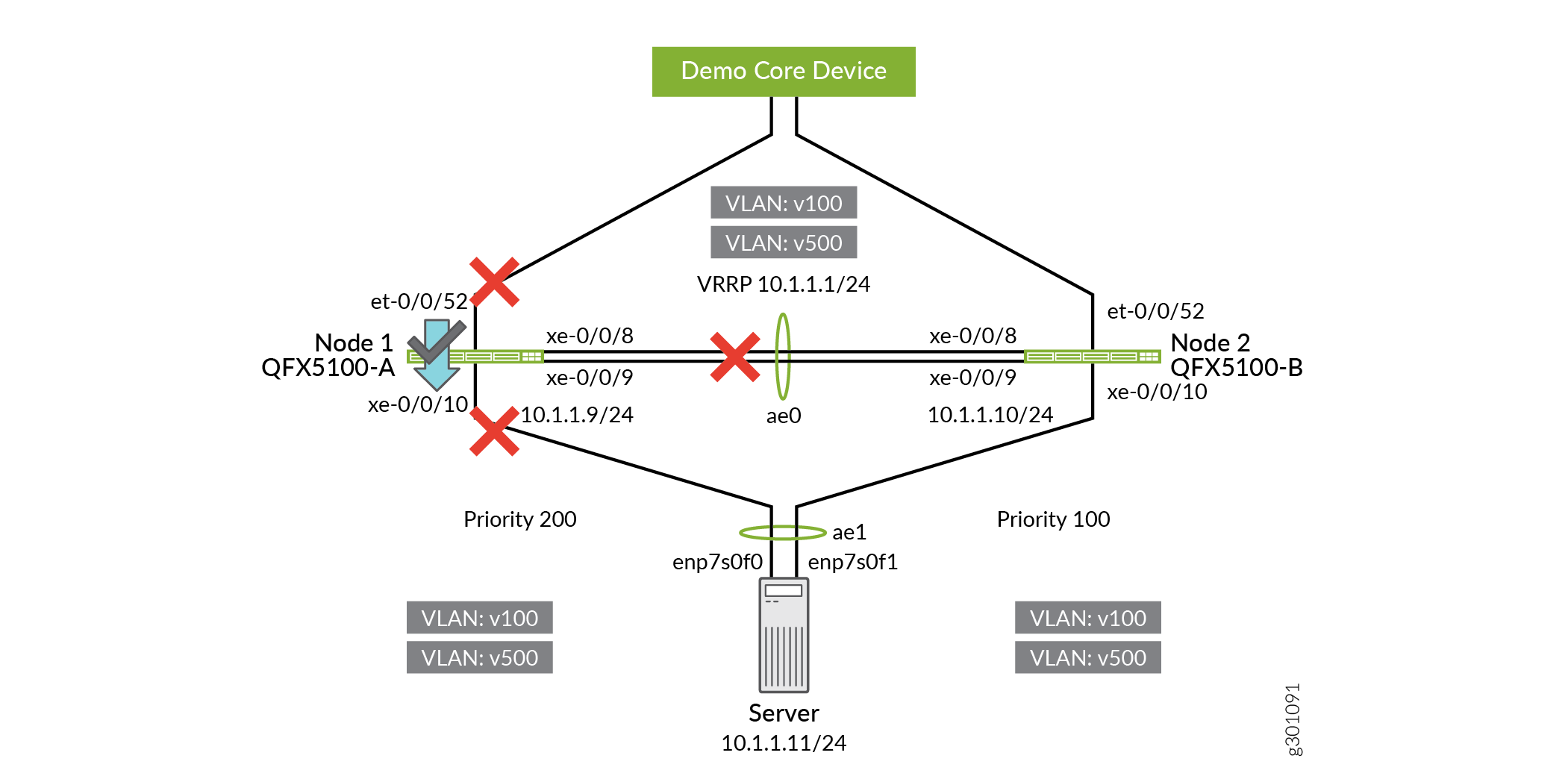
To redirect the traffic from QFX5100-B to QFX5100-A, re-enable the server-facing and uplink interfaces on QFX5100-A.
user@QFX5100-A# delete interfaces xe-0/0/10 disable user@QFX5100-A# delete interfaces et-0/0/52 disable user@QFX5100-A# commit and-quit
Figure 7: Re-enabling Server-Facing and Uplink Interfaces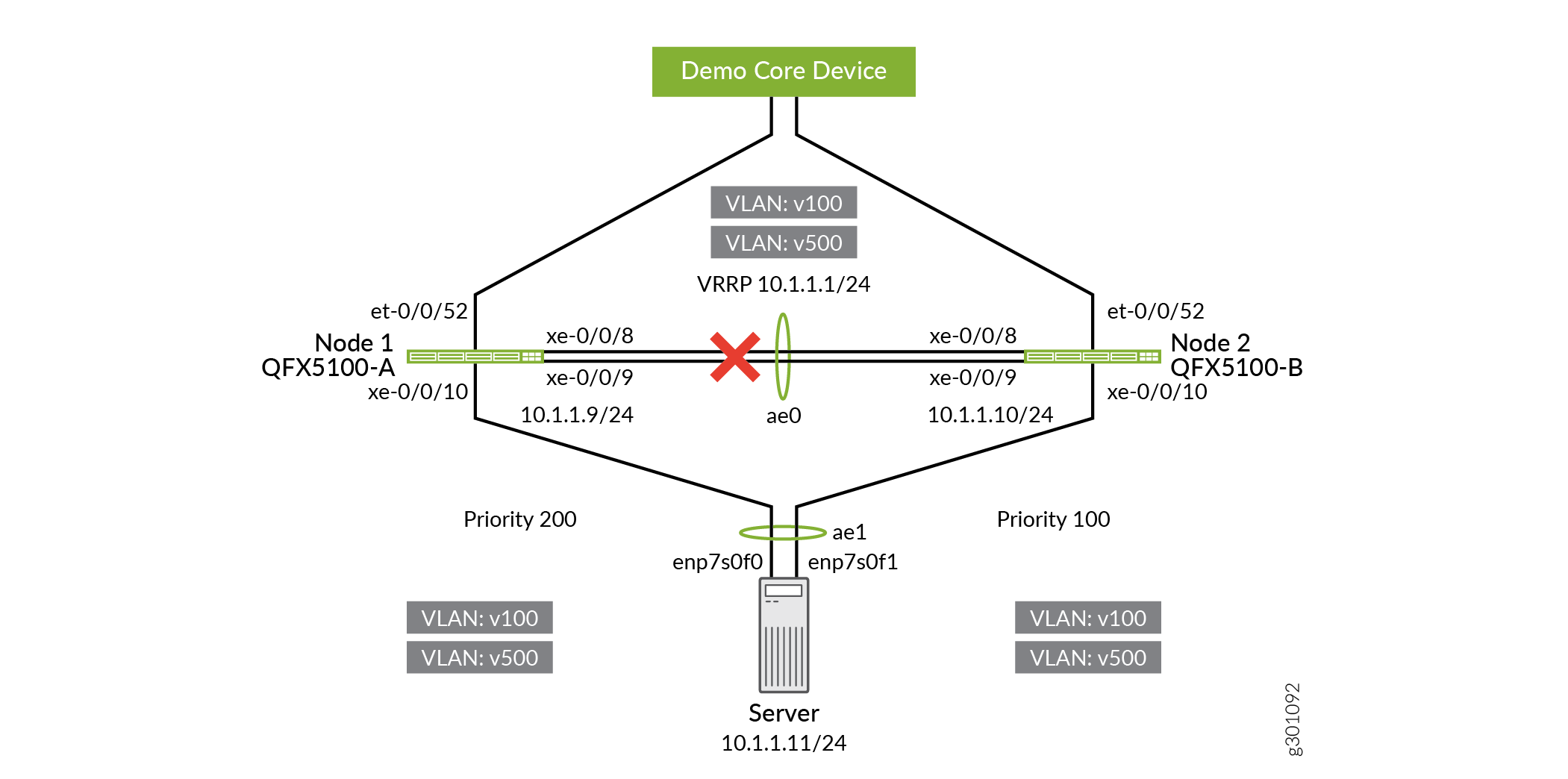
Disable the server-facing interfaces on QFX5100-B.
user@QFX5100-B# set interfaces xe-0/0/10 disable user@QFX5100-B# commit and-quit
Figure 8: Disabling Server-Facing Interfaces on QFX5100-B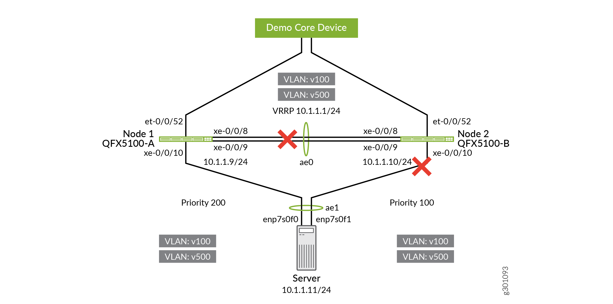
Disable the uplink interfaces on QFX5100-B, so that the traffic goes through QFX5100-A.
user@QFX5100-B# set interfaces et-0/0/52 disable user@QFX5100-B# commit and-quit
Figure 9: Disabling Uplink Interfaces on QFX5100-B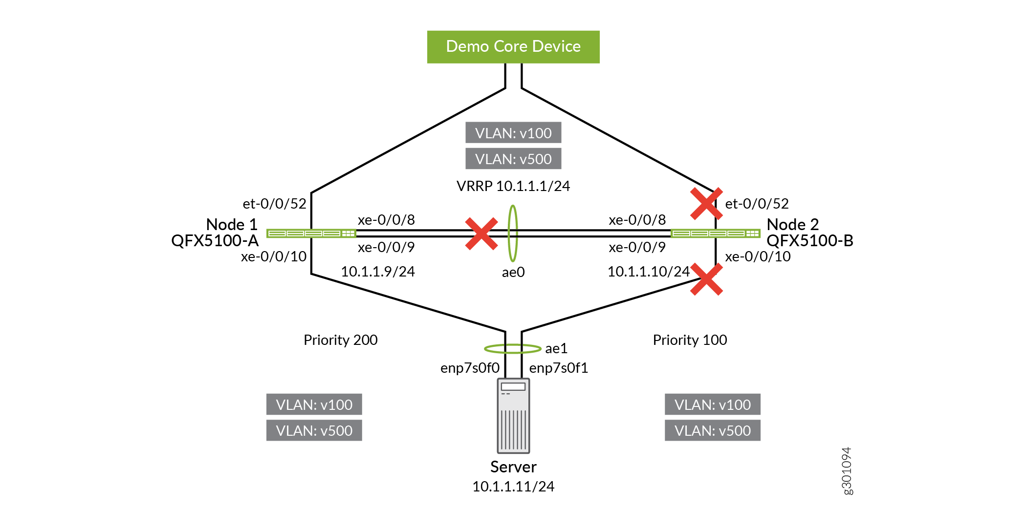
Upgrade QFX5100-B.
user@QFX5100-B> request system software add /var/tmp/jinstall-host-qfx-5-18.4R3.3-signed.tgz reboot
Figure 10: Upgrading QFX5100-B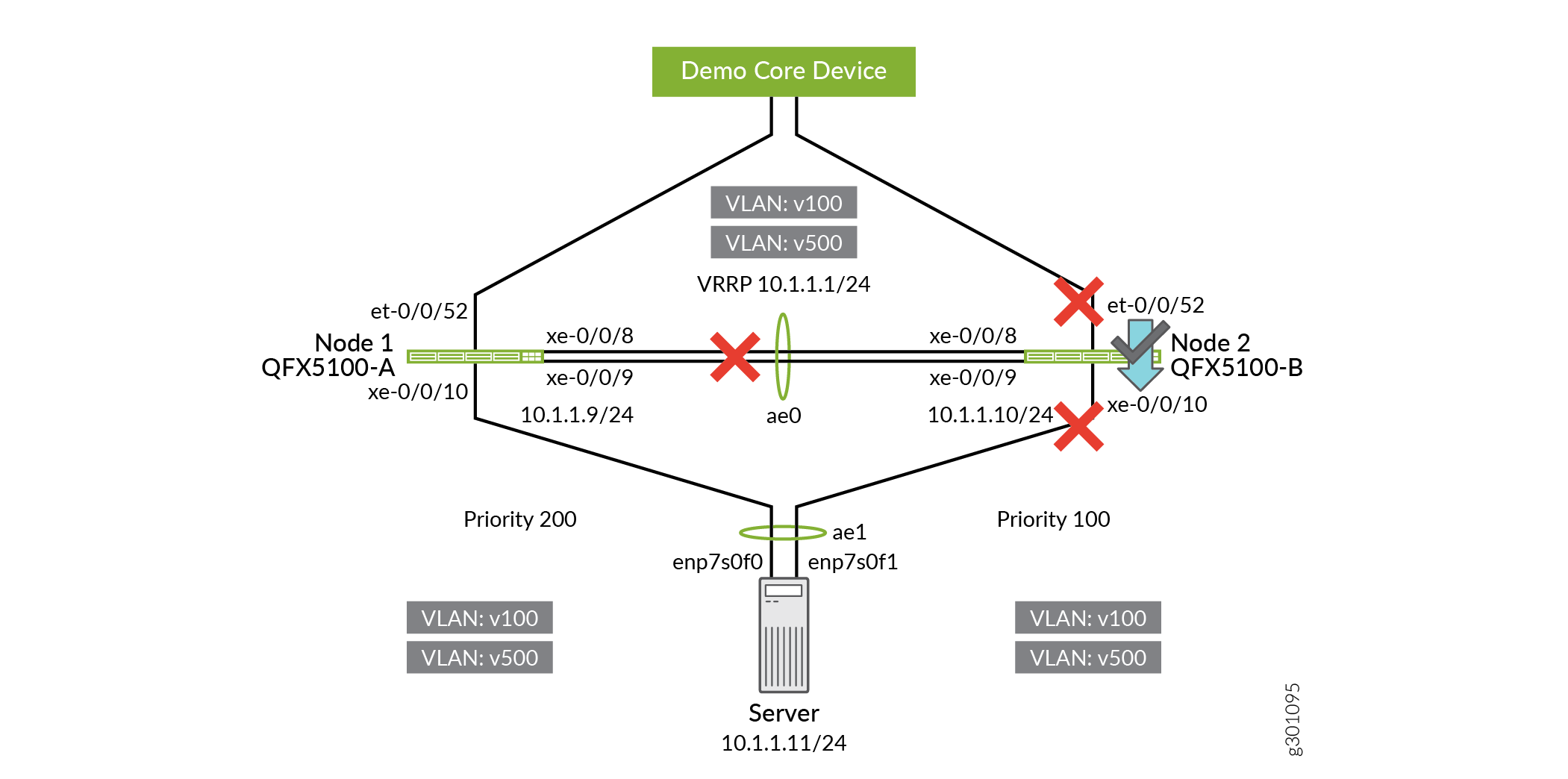
Re-enable the ICCP-PL interface between QFX5100-A and QFX5100-B.
user@QFX5100-A# delete interfaces xe-0/0/8 disable user@QFX5100-A# delete interfaces xe-0/0/9 disable user@QFX5100-A# commit and-quit
user@QFX5100-B# delete interfaces xe-0/0/8 disable user@QFX5100-B# delete interfaces xe-0/0/9 disable user@QFX5100-B# commit and-quit
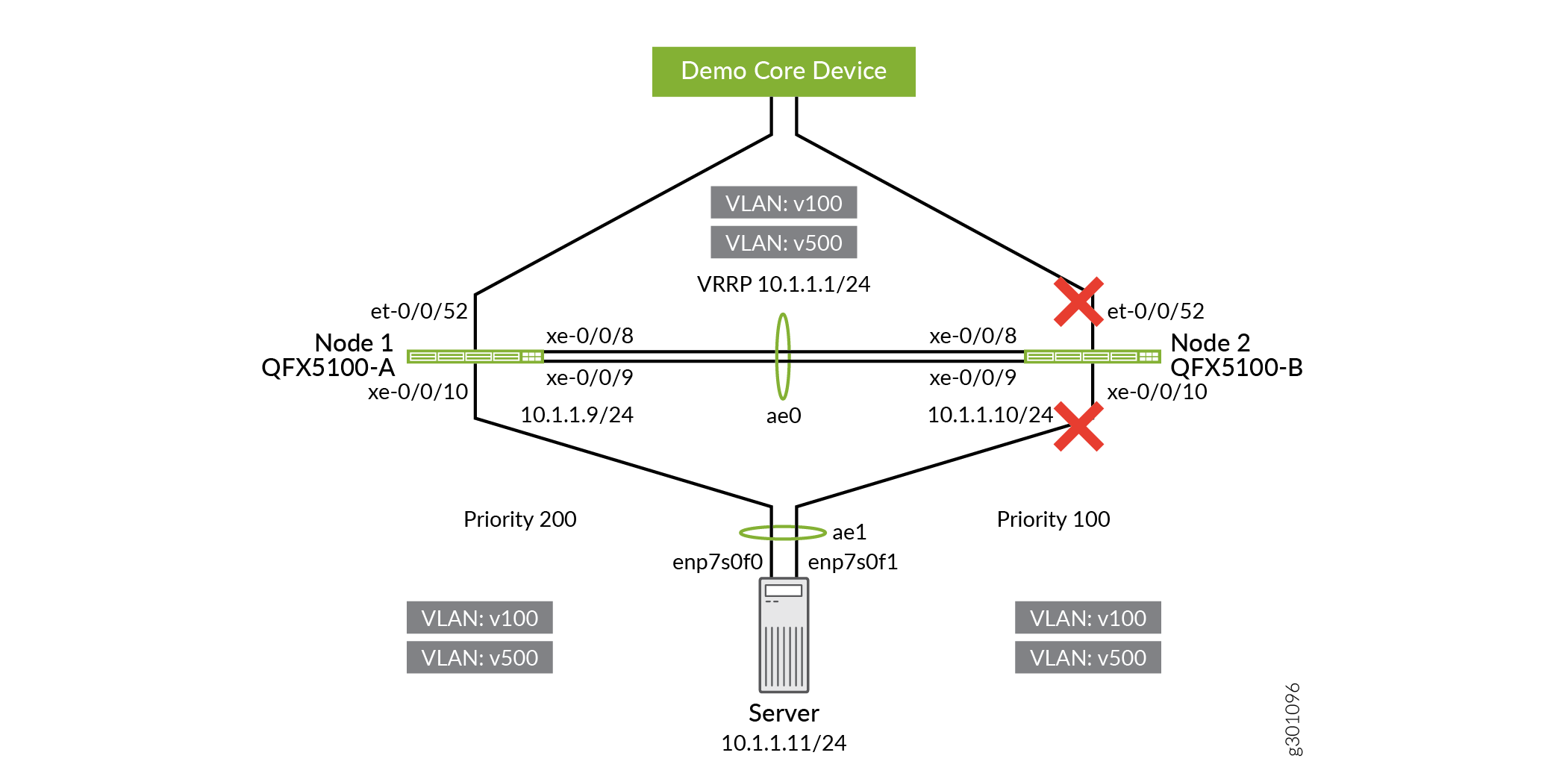
Re-enable the server-facing and uplink interfaces on QFX5100-B.
user@QFX5100-B# delete interfaces xe-0/0/10 disable user@QFX5100-B# delete interfaces et-0/0/52 disable user@QFX5100-B# commit and-quit

Verification
Verify that the MC-LAG Fabric is Operational
Purpose
Verify that the MC-LAG Fabric is operational.
Action
user@QFX5100-A> show interfaces mc-ae
Current State Machine's State: mcae active state
Local Status : active
Local State : up
Peer Status : active
Peer State : up
Logical Interface : ae1.0
Topology Type : bridge
Local State : up
Peer State : up
Peer Ip/MCP/State : 10.3.3.1 ae0.0 up
user@QFX5100-A> show iccp
Redundancy Group Information for peer 10.3.3.1
  TCP Connection       : Established
  Liveliness Detection : Up
  Backup liveness peer status: Up
  Redundancy Group ID          Status
    1                           Up
Client Application: lacpd
  Redundancy Group IDs Joined: 1

Client Application: l2ald_iccpd_client
  Redundancy Group IDs Joined: 1
user@QFX5100-A> show lacp interfaces ae0
Aggregated interface: ae0
    LACP state:       Role   Exp   Def  Dist  Col  Syn  Aggr  Timeout  Activity
      xe-0/0/8       Actor    No    No   Yes  Yes  Yes   Yes     Fast    Active
      xe-0/0/8     Partner    No    No   Yes  Yes  Yes   Yes     Fast    Active
      xe-0/0/9       Actor    No    No   Yes  Yes  Yes   Yes     Fast    Active
      xe-0/0/9     Partner    No    No   Yes  Yes  Yes   Yes     Fast    Active
    LACP protocol:        Receive State  Transmit State          Mux State
      xe-0/0/8                  Current   Fast periodic Collecting distributing
      xe-0/0/9                  Current   Fast periodic Collecting distributing
user@QFX5100-A> show lacp interfaces ae1
Aggregated interface: ae1
    LACP state:       Role   Exp   Def  Dist  Col  Syn  Aggr  Timeout  Activity
      xe-0/0/10      Actor    No    No   Yes  Yes  Yes   Yes     Fast    Active
      xe-0/0/10    Partner    No    No   Yes  Yes  Yes   Yes     Fast    Active
    LACP protocol:        Receive State  Transmit State          Mux State
      xe-0/0/10                 Current   Fast periodic Collecting distributing
Meaning
You can see that the MC-LAG is operational because the MC-AE interface and ICCP connections are up.
Verify that the New Version of Junos OS is Installed
Purpose
Verify that the new version of Junos OS is installed on QFX5100-A and QFX5100-B.
Action
user@QFX5100-A> show version
fpc0:
--------------------------------------------------------------------------
Hostname: QFX5100-A
Model: qfx5100-48s-6q
Junos: 18.4R3.3
JUNOS Base OS Software Suite [18.4R3.3]
JUNOS Base OS boot [18.4R3.3]
JUNOS Crypto Software Suite [18.4R3.3]
JUNOS Crypto Software Suite [18.4R3.3]
JUNOS Online Documentation [18.4R3.3]
JUNOS Kernel Software Suite [18.4R3.3]
JUNOS Packet Forwarding Engine Support (qfx-ex-x86-32) [18.4R3.3]
JUNOS Routing Software Suite [18.4R3.3]
JUNOS jsd [i386-18.4R3.3-jet-1]
JUNOS SDN Software Suite [18.4R3.3]
JUNOS Enterprise Software Suite [18.4R3.3]
JUNOS Web Management Platform Package [18.4R3.3]
JUNOS Openconfig [18.4R3.3]
JUNOS py-base-i386 [18.4R3.3]
JUNOS py-extensions-i386 [18.4R3.3]
JUNOS Host Software [17.3R3.9]
user@QFX5100-B> show version
fpc0:
--------------------------------------------------------------------------
Hostname: QFX5100-B
Model: qfx5100-48s-6q
Junos: 18.4R3.3
JUNOS Base OS Software Suite [18.4R3.3]
JUNOS Base OS boot [18.4R3.3]
JUNOS Crypto Software Suite [18.4R3.3]
JUNOS Crypto Software Suite [18.4R3.3]
JUNOS Online Documentation [18.4R3.3]
JUNOS Kernel Software Suite [18.4R3.3]
JUNOS Packet Forwarding Engine Support (qfx-ex-x86-32) [18.4R3.3]
JUNOS Routing Software Suite [18.4R3.3]
JUNOS jsd [i386-18.4R3.3-jet-1]
JUNOS SDN Software Suite [18.4R3.3]
JUNOS Enterprise Software Suite [18.4R3.3]
JUNOS Web Management Platform Package [18.4R3.3]
JUNOS Openconfig [18.4R3.3]
JUNOS py-base-i386 [18.4R3.3]
JUNOS py-extensions-i386 [18.4R3.3]
JUNOS Host Software [17.3R3.9]
Meaning
You can see that Junos OS 18.4R3.3 is installed on QFX5100-A and QFX5100-B.
Conclusion
Manually upgrading QFX Series MC-LAG Fabric
Step-by-Step Procedure
Device Configuration Details
Procedure
Step-by-Step Procedure
This is the MC-LAG configuration used in this example.
QFX5100-A
set chassis aggregated-devices ethernet device-count 2
set interfaces xe-0/0/8 ether-options 802.3ad ae0
set interfaces xe-0/0/9 ether-options 802.3ad ae0
set interfaces xe-0/0/10 ether-options 802.3ad ae1
set interfaces ae0 aggregated-ether-options lacp active
set interfaces ae0 unit 0 family ethernet-switching interface-mode trunk
set interfaces ae0 unit 0 family ethernet-switching vlan members v500
set interfaces ae0 unit 0 family ethernet-switching vlan members v100
set interfaces ae1 aggregated-ether-options lacp active
set interfaces ae2 aggregated-ether-options lacp periodic fast
set interfaces ae1 aggregated-ether-options lacp system-id 00:01:02:03:04:05
set interfaces ae1 aggregated-ether-options lacp admin-key 3
set interfaces ae1 aggregated-ether-options mc-ae mc-ae-id 3
set interfaces ae1 aggregated-ether-options mc-ae chassis-id 0
set interfaces ae1 aggregated-ether-options mc-ae mode active-active
set interfaces ae1 aggregated-ether-options mc-ae status-control active
set interfaces ae1 aggregated-ether-options mc-ae init-delay-time 240
set interfaces ae1 unit 0 family ethernet-switching interface-mode access
set interfaces ae1 unit 0 family ethernet-switching vlan members v100
set interfaces irb unit 100 family inet address 10.1.1.9/24 vrrp-group 100 virtual-address 10.1.1.1
set interfaces irb unit 100 family inet address 10.1.1.9/24 vrrp-group 100 priority 200
set interfaces irb unit 100 family inet address 10.1.1.9/24 vrrp-group 100 accept-data
set interfaces irb unit 500 family inet address 10.3.3.2/24
set multi-chassis multi-chassis-protection 10.3.3.1 interface ae0
set protocols iccp local-ip-addr 10.3.3.2
set protocols iccp peer 10.3.3.1 session-establishment-hold-time 340
set protocols iccp peer 10.3.3.1 redundancy-group-id-list 1
set protocols iccp peer 10.3.3.1 backup-liveness-detection backup-peer-ip 10.92.71.88
set protocols iccp peer 10.3.3.1 liveness-detection minimum-receive-interval 60
set protocols iccp peer 10.3.3.1 liveness-detection transmit-interval minimum-interval 60
set protocols rstp interface ae0 disable
set protocols rstp interface ae1 edge
set protocols rstp interface all mode point-to-point
set protocols rstp bpdu-block-on-edge
set switch-options service-id 6
set vlans v100 vlan-id 100
set vlans v100 l3-interface irb.100
set vlans v100 mcae-mac-synchronize
set vlans v500 vlan-id 500
set vlans v500 l3-interface irb.500
Step-by-Step Procedure
QFX5100-B
set chassis aggregated-devices ethernet device-count 2
set interfaces xe-0/0/8 ether-options 802.3ad ae0
set interfaces xe-0/0/9 ether-options 802.3ad ae0
set interfaces xe-0/0/10 ether-options 802.3ad ae1
set interfaces ae0 aggregated-ether-options lacp active
set interfaces ae0 unit 0 family ethernet-switching interface-mode trunk
set interfaces ae0 unit 0 family ethernet-switching vlan members v500
set interfaces ae0 unit 0 family ethernet-switching vlan members v100
set interfaces ae1 aggregated-ether-options lacp active
set interfaces ae2 aggregated-ether-options lacp periodic fast
set interfaces ae1 aggregated-ether-options lacp system-id 00:01:02:03:04:05
set interfaces ae1 aggregated-ether-options lacp admin-key 3
set interfaces ae1 aggregated-ether-options mc-ae mc-ae-id 3
set interfaces ae1 aggregated-ether-options mc-ae chassis-id 1
set interfaces ae1 aggregated-ether-options mc-ae mode active-active
set interfaces ae1 aggregated-ether-options mc-ae status-control standby
set interfaces ae1 aggregated-ether-options mc-ae init-delay-time 240
set interfaces ae1 unit 0 family ethernet-switching interface-mode access
set interfaces ae1 unit 0 family ethernet-switching vlan members v100
set interfaces irb unit 100 family inet address 10.1.1.10/24 vrrp-group 100 virtual-address 10.1.1.1
set interfaces irb unit 100 family inet address 10.1.1.10/24 vrrp-group 100 priority 100
set interfaces irb unit 100 family inet address 10.1.1.10/24 vrrp-group 100 accept-data
set interfaces irb unit 500 family inet address 10.3.3.1/24
set multi-chassis multi-chassis-protection 10.3.3.2 interface ae0
set protocols iccp local-ip-addr 10.3.3.1
set protocols iccp peer 10.3.3.2 session-establishment-hold-time 340
set protocols iccp peer 10.3.3.2 redundancy-group-id-list 1
set protocols iccp peer 10.3.3.2 backup-liveness-detection backup-peer-ip 10.92.71.87
set protocols iccp peer 10.3.3.2 liveness-detection minimum-receive-interval 60
set protocols iccp peer 10.3.3.2 liveness-detection transmit-interval minimum-interval 60
set protocols rstp interface ae0 disable
set protocols rstp interface ae1 edge
set protocols rstp interface all mode point-to-point
set protocols rstp bpdu-block-on-edge
set switch-options service-id 6
set vlans v100 vlan-id 100
set vlans v100 l3-interface irb.100
set vlans v100 mcae-mac-synchronize
set vlans v500 vlan-id 500
set vlans v500 l3-interface irb.500