Migrate a Virtual Chassis Fabric to an EVPN-VXLAN Bridging Overlay Fabric
About This Network Configuration Example
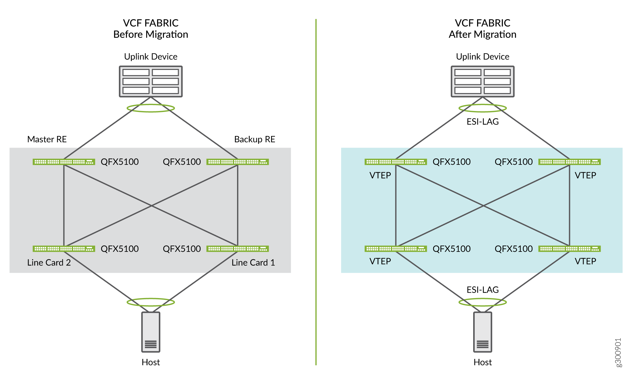
This NCE shows how to migrate a four-member Virtual Chassis fabric (VCF) to an EVPN-VXLAN bridged overlay fabric. A VCF serves customers with a centrally managed Layer 2 fabric well. However, in a centrally managed fabric there can be downtime caused by maintenance and upgrades. You can avoid this downtime by moving to a distributed control plane. In this case, we recommend migrating your VCF to an EVPN-VXLAN bridged overlay fabric. Another reason to upgrade your VCF is that there will be limited support for VCF in future Junos releases.
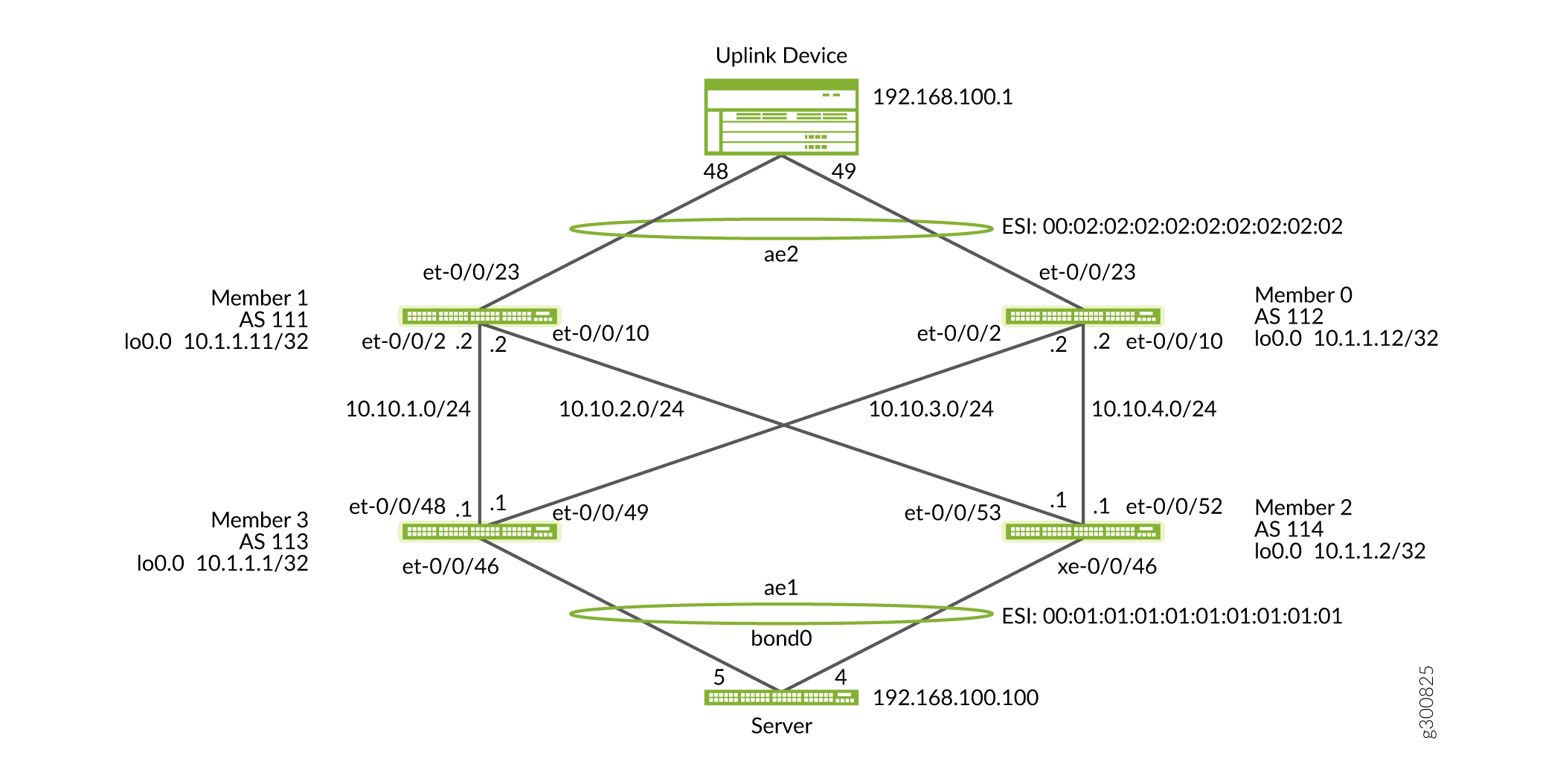
Figure 1 shows a before and after of a VCF to EVPN-VXLAN configuration.
See Also
How to Migrate a Virtual Chassis Fabric to an EVPN Bridging Overlay Fabric
Requirements
We use the following in this example:
A two-spine and two-leaf VCF composed of QFX5100 switches running Junos OS Release 14.1X53-D47.6 that we will upgrade to Release 18.4R2.7, which is an EVPN-recommended release.
A server that is dual-homed to the VCF leaf devices. We recommend that the server be dual-homed to the leaf devices because a single homed server requires downtime to perform this migration.
Incorporate MTU 9216 on fabric (leaf and spine) underlay links and 9100 bytes on PE to CE links (AE interfaces level MTU).
Pre-provisioned mode VCF
Layer 2-only VCF
Console access to all devices
A reachable FTP server
Junos OS Release 18.4R2.7 or later EVPN recommended release
Overview
The key changes to move from a VCF to EVPN-VXLAN configuration are:
Adding an EBGP underlay
Adding an IBGP overlay
VLAN to VNI mapping
Addition of EVPN-VXLAN signaling, switch-options and related import and export policy statements
Changing LAG towards uplink device and and downlink servers to ESI-LAGs
To migrate the VCF to an EVPN-VXLAN fabric:
Split the existing VCF into halves and isolate the backup Routing Engine and one device in a line card role.
Migrate the isolated half to EVPN-VXLAN while traffic is still passing through the other half.
Isolate and migrate the remaining half while directing the traffic through the new EVPN-VXLAN fabric.
Join all the devices into a single EVPN-VXLAN fabric.
Topology
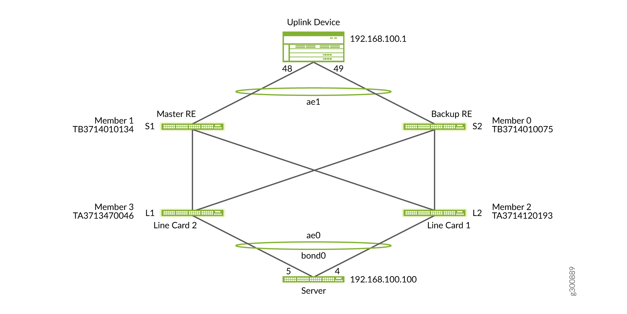
Figure 2 illustrates the topology of the VCF. Members 1 and 0 are connected to the uplink device, while the line cards are connected to the server.
Configuration
- Prepare for the Migration
- Reroute Traffic Through Member 1 and Member 3
- Upgrade Member 0 and Member 2
- Zeroize Member 0 and Member 2
- Configure Member 0 and Member 2
- Configure the Underlay and EVPN-VXLAN Overlay for Member 0
- Configure the Underlay and EVPN-VXLAN Overlay on Member 2
- Configure the Bond Interface on Host Server
- Move the Traffic Flow from VCF to the New EVPN-VXLAN Fabric
- Migrate and Zeroize Member 1 and Member 3
- Configure the Underlay and EVPN-VXLAN Overlay for Member 1
- Configure the Underlay and EVPN-VXLAN Overlay for Member 3
- Control Plane Convergence
- Verification
Prepare for the Migration
Before you begin, create a topology diagram of your VCF like in Figure 2, copy the new Junos OS image to your devices, and monitor the traffic flow.
Step-by-Step Procedure
Check the status of the VCF before you begin the migration. Note the serial numbers, member IDs, and associated roles of the devices.
user@switch> show virtual-chassis

Preprovisioned Virtual Chassis Fabric
Fabric ID: 123a.123b.123c
Fabric Mode: Enabled
                                      Mstr        Mixed Route Neighbor List
Member ID  Status Serial No    Model  prio  Role   Mode  Mode ID  Interface
0 (FPC 0)  Prsnt  XXXXXXXX000  ...    129   Backup    N  F    2  vcp-255/0/10
                                                              3  vcp-255/0/2
1 (FPC 1)  Prsnt  XXXXXXXX001  ...    129   Master*   N  F    2  vcp-255/0/10
                                                              3  vcp-255/0/2
2 (FPC 2)  Prsnt  XXXXXXXX002  ...      0   Linecard  N  F    0  vcp-255/0/52
                                                              1  vcp-255/0/53
3 (FPC 3)  Prsnt  XXXXXXXX003  ...      0   Linecard  N  F    1  vcp-255/0/48
                                                              0  vcp-255/0/49
Check the Virtual Chassis ports (VCPs) and create a topology diagram for reference.
user@switch> show virtual-chassis vc-port

fpc0:
--------------------------------------------------------------------------
Interface   Type              Trunk  Status       Speed        Neighbor
or                             ID                 (mbps)       ID  Interface
PIC / Port
0/10        Configured         -1    Up           40000        2   vcp-255/0/52
0/2         Configured         -1    Up           40000        3   vcp-255/0/49

fpc1:
--------------------------------------------------------------------------
Interface   Type              Trunk  Status       Speed        Neighbor
or                             ID                 (mbps)       ID  Interface
PIC / Port
0/10        Configured         -1    Up           40000        2   vcp-255/0/53
0/2         Configured         -1    Up           40000        3   vcp-255/0/48

fpc2:
--------------------------------------------------------------------------
Interface   Type              Trunk  Status       Speed        Neighbor
or                             ID                 (mbps)       ID  Interface
PIC / Port
0/52        Configured         -1    Up           40000        0   vcp-255/0/10
0/53        Configured         -1    Up           40000        1   vcp-255/0/10

fpc3:
--------------------------------------------------------------------------
Interface   Type              Trunk  Status       Speed        Neighbor
or                             ID                 (mbps)       ID  Interface
PIC / Port
0/48        Configured         -1    Up           40000        1   vcp-255/0/2
0/49        Configured         -1    Up           40000        0   vcp-255/0/2
Check that all four members are present. Check the Junos OS release running on each device. Each device must be running the same Junos OS release. If there is a release mismatch, the device shows as inactive.
user@switch> show version
fpc0:
--------------------------------------------------------------------------
Hostname: switch
Model: qfx5100-24q-2p
Junos: 14.1X53-D47.6
JUNOS Base OS Software Suite [14.1X53-D47.6]
JUNOS Base OS boot [14.1X53-D47.6]

fpc1:
--------------------------------------------------------------------------
Hostname: switch
Model: qfx5100-24q-2p
Junos: 14.1X53-D47.6
JUNOS Base OS Software Suite [14.1X53-D47.6]
JUNOS Base OS boot [14.1X53-D47.6]

fpc2:
--------------------------------------------------------------------------
Hostname: switch
Model: qfx5100-48s-6q
Junos: 14.1X53-D47.6
JUNOS Base OS Software Suite [14.1X53-D47.6]
JUNOS Base OS boot [14.1X53-D47.6]

fpc3:
--------------------------------------------------------------------------
Hostname: switch
Model: qfx5100-48s-6q
Junos: 14.1X53-D47.6
JUNOS Base OS Software Suite [14.1X53-D47.6]
JUNOS Base OS boot [14.1X53-D47.6]
JUNOS Crypto Software Suite [14.1X53-D47.6]
JUNOS Online Documentation [14.1X53-D47.6]
Copy the recommended Junos release for running EVPN to all the devices. Use FTP to copy the new Junos OS image to the primary Routing Engine. Then copy the new image from the primary Routing Engine to the other VCF members.
To copy the image from the /var/tmp directory on the primary Routing Engine to Member 3, also called fpc 3:
file copy /var/tmp/jinstall-host-qfx-5-flex-18.4R2.7-signed.tgz fpc3:/var/tmp
Figure 3 Illustrates how the new Junos OS image is distributed among the members.
Figure 3: Copy Junos OS Image to VCF members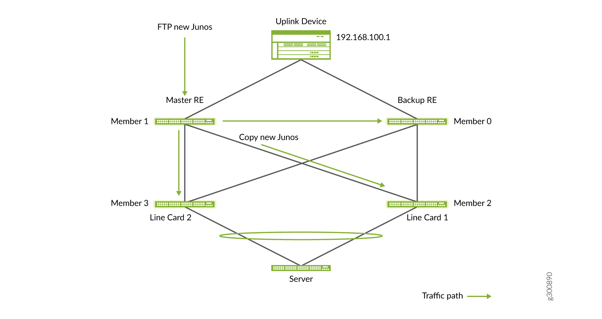
Do the same for the other members. The FPC number is the same as the member number. For example:
file copy /var/tmp/jinstall-host-qfx-5-flex-18.4R2.7-signed.tgz fpc0:/var/tmp
file copy /var/tmp/jinstall-host-qfx-5-flex-18.4R2.7-signed.tgz fpc2:/var/tmp
Access each member from the VCF primary Routing Engine and confirm that the file was copied to each member. For example, to access Member 3:
{master:1}
user@switch> request session Member 3

--- JUNOS 14.1X53-D47.6 built 2018-09-08 01:46:47 UTC
Next, check the /var/tmp directory on this VCF member for the new Junos OS image.
user@switch:LC:3% cd /var/tmp/
user@switch:LC:3% ls -ltr
total 1222684
-r--r--r--  1 user  field        505 Apr 18 19:05 preinstall_boot_loader.conf
-rw-r--r--  1 user  field         42 Apr 18 19:07 vjunos-install.log
drwxr-xr-x  2 user  field        512 Apr 18 19:14 gres-tp
drwxrwxrwt  2 user  wheel        512 Apr 18 19:14 vi.recover
drwxrwxrwx  2 user  wheel        512 Apr 18 19:14 pics
drwxrwxrwx  2 user  wheel        512 Apr 18 19:14 install
-rw-r--r--  1 user  field          0 Apr 18 19:27 stable
-rw-r-----  1 user  field       1043 Apr 18 19:30 juniper.conf+.gz
-rw-r--r--  1 user  field  625814976 Apr 19 21:28 jinstall-host-qfx-5-flex-18.4R2.7-signed.tgz
When you are done, use
exitto return to the primary device.user@switch:LC:3% exit
Repeat the image check on each device in the VCF.
To check for any traffic loss during the procedure, start a continuous ping from the server to IRB 192.168.100.1 on the uplink device.
user@router> ping 192.168.100.1

PING 192.168.100.1 (192.168.100.1) 56(84) bytes of data.
64 bytes from 192.168.100.1: icmp_seq=1 ttl=64 time=3.33 ms
64 bytes from 192.168.100.1: icmp_seq=2 ttl=64 time=6.84 ms
64 bytes from 192.168.100.1: icmp_seq=3 ttl=64 time=7.87 ms
64 bytes from 192.168.100.1: icmp_seq=4 ttl=64 time=5.91 ms
. . .
Reroute Traffic Through Member 1 and Member 3
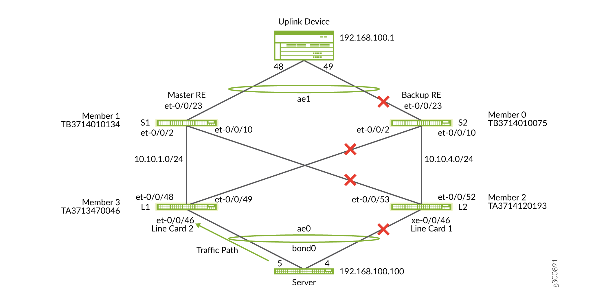
To start the migration procedure, first isolate the half of the VCF that contains the backup Routing Engine and one device in the linecard role: Members 0 and 2. To do so, on Member 0, disable the interfaces to the uplink device and Member 3. On Member 2, disable the interface to Member 1 and the server. At this point, we have split the VCF in half. Traffic is still forwarded through the other line card, through the primary Routing Engine, and finally to the uplink MX Series router.
Step-by-Step Procedure
Using the figure above, identify the member interfaces and VCPs you need to disable on Members 0 and 2 to isolate them from the rest of the VCF. The VCPs you disable are port 2 on Member 0 and port 53 on Member 2. Before you delete any VCPs enable ‘no split-detection’ on the entire VCF.
set virtual-chassis no-split-detection
Use the command below on the primary Routing Engine (Member 1) to determine the names of the relevant interfaces. You will disable the LACP member interfaces towards the uplink device and servers. In this case, et-0/0/23.0 is the Member 0 upstream interface and xe-2/0/46.0 is the Member 2 downstream interface.
{master:1}
user@switch> show interfaces terse | match ae

et-0/0/23.0             up    up   aenet    --> ae1.0
et-1/0/23.0             up    up   aenet    --> ae1.0
xe-2/0/46.0             up    up   aenet    --> ae0.0
xe-3/0/46.0             up    up   aenet    --> ae0.0
ae0                     up    up
ae0.0                   up    up   eth-switch
ae1                     up    up
ae1.0                   up    up   eth-switch
Access the primary (Member 1) console and do the following:
Disable the interface on Member 0 to the uplink device.
set interfaces et-0/0/23 disable
Disable the interface from Member 2 to the server.
set interfaces xe-2/0/46 disable
Commit the configuration for it to take effect.
Delete the VCP from Member 0 towards Member 3.
user@switch> request virtual-chassis vc-port delete pic-slot 0 port 2 Member 0
Delete the VCP from Member 2 towards Member 1.
user@switch>request virtual-chassis vc-port delete pic-slot 0 port 53 Member 2
Check that the members were removed from the VCF and marked as
NotPrsnt.user@switch> show virtual-chassis Preprovisioned Virtual Chassis Fabric Fabric ID: 123a.123b.123c Fabric Mode: Enabled Mstr Mixed Route Neighbor List Member ID Status Serial No Model prio Role Mode Mode ID Interface 0 (FPC 0) NotPrsnt XXXXXXXX000 ... 1 (FPC 1) Prsnt XXXXXXXX001 ... 129 Master* N F 3 vcp-255/0/2 2 (FPC 2) NotPrsnt XXXXXXXX002 ... 3 (FPC 3) Prsnt XXXXXXXX003 ... 0 Linecard N F 1 vcp-255/0/48
Upgrade Member 0 and Member 2
Separate member 0 and member 2 by deleting the VCP between both devices. On member 0 apply the following commands:
user@member0> request virtual-chassis vc-port delete pic-slot 0 port 52 Member 3user@member0> request virtual-chassis vc-port delete pic-slot local 0 port 10
Now that you have isolated Member 0 and Member 2, you can upgrade these devices. Notice that the only traffic path is through Members 1 and 3.
Step-by-Step Procedure
-
Access the consoles for Members 0 and 2. Enter the following command to upgrade both members to the Junos OS image that was copied onto the devices.
user@switch> request system software add /var/tmp/jinstall-host-qfx-5-flex-18.4R2.7-signed.tgz no-copy no-validate reboot
-
Confirm the update was successful.
{linecard:2} user@Member0> show version fpc0: -------------------------------------------------------------------------- Hostname: switch Model: qfx5100-24q-2p Junos 18.4R2.7 JUNOS Base OS Software Suite [18.4R2.7] JUNOS Base OS boot [18.4R2.7] . . .{linecard:2} user@member2> show version fpc2: -------------------------------------------------------------------------- Hostname: switch Model: qfx5100-48s-6q Junos: 18.4R2.7 JUNOS Base OS Software Suite [18.4R2.7] . . .
Zeroize Member 0 and Member 2
Once Member 0 and 2 are migrated to a recommended EVPN-VXLAN release, zeroize both switches. Zeroizing the switches ensures that the residual VCF configuration and logs are removed from each switch.
{master:0}user@member0>request system zeroizeuser@member2> request system zeroize
Once the switches reboot, restore the out-of-band management network connectivity.
Step-by-Step Procedure
Configure Member 0 and Member 2
Use the next steps to configure the underlay on Member 0 and Member 2. We identify the switches using member numbers for the sake of clarity even though the VCF does not exist yet. Configure the switches with the interface and loopback addresses, autonomous system (AS) numbers, and other components of the final EVPN-VXLAN fabric.
Step-by-Step Procedure
Configure the Underlay and EVPN-VXLAN Overlay for Member 0
Step-by-Step Procedure
Configure the interfaces (Keep the uplink interface for Member 0 disabled).
set interfaces et-0/0/23 disable
set interfaces et-0/0/2 unit 0 family inet address 10.10.3.2/24
set interfaces et-0/0/10 unit 0 family inet address 10.10.4.2/24
Configure the loopback interfaces for Member 0.
set interfaces lo0 unit 0 family inet address 10.1.1.12/32 primary
set interfaces lo0 unit 0 family inet address 10.1.1.12/32 preferred
Configure the underlay external BGP (EBGP) for Member 0.
set protocols bgp group underlay type external
set protocols bgp group underlay export VTEPS
set protocols bgp group underlay export direct
set protocols bgp group underlay local-as 112
set protocols bgp group underlay multipath multiple-as
set protocols bgp group underlay neighbor 10.10.4.1 peer-as 114
set protocols bgp group underlay neighbor 10.10.3.1 peer-as 113
Configure the overlay internal BGP (IBGP) for Member 0.
user@switc#>
set protocols bgp group overlay type internal
set protocols bgp group overlay local-address 10.1.1.12
set protocols bgp group overlay family evpn signaling
set protocols bgp group overlay vpn-apply-export
set protocols bgp group overlay cluster 10.1.1.12
set protocols bgp group overlay local-as 64513
set protocols bgp group overlay multipath
set protocols bgp group overlay neighbor 10.1.1.1
set protocols bgp group overlay neighbor 10.1.1.2
Configure the VLAN to VXLAN network identifier (VNI) mapping for Member 0.
 set vlans default vlan-id 1
set vlans default l3-interface irb.0
set vlans v100 vlan-id 100
set vlans v100 vxlan vni 10100
Configure the protocol EVPN-VXLAN configuration and route targets for each VNI for Member 0.
set protocols evpn vni-options vni 10100 vrf-target target:64513:100
set protocols evpn encapsulation vxlan
set protocols evpn multicast-mode ingress-replication
set protocols evpn extended-vni-list 10100
set protocols evpn extended-vni-list all
Configure the default switch options for Member 0.
set switch-options vtep-source-interface lo0.0
set switch-options route-distinguisher 10.1.1.12:1
set switch-options vrf-import my-fabric
set switch-options vrf-target target:1:9999
Configure the routing options for Member 0.
set routing-options static route 0.0.0.0/0 next-hop 10.92.71.254
set routing-options router-id 10.1.1.12
set routing-options autonomous-system 112
set routing-options forwarding-table export LB
Configure the policy options for Member 0.
set policy-options policy-statement LB then load-balance per-packet
set policy-options policy-statement VTEPS term term1 from route-filter 10.1.1.0/24 prefix-length-range /32-/32
set policy-options policy-statement VTEPS term term1 then accept
set policy-options policy-statement VTEPS term term2 then reject
set policy-options policy-statement direct term term10 from protocol direct
set policy-options policy-statement direct term term10 then accept
set policy-options policy-statement my-fabric term term1 from community my-fab-com
set policy-options policy-statement my-fabric term term1 then accept
set policy-options policy-statement my-fabric term term2 from community my-vni10100
set policy-options policy-statement my-fabric term term2 then accept
set policy-options community my-fab-com members target:1:9999
set policy-options community my-vni10100 members target:64513:100
On Member 0 configure ESI LAG to the uplink device. The ESI LAG pair for Member 0 is Member 1 after Member 1 is migrated to EVPN-VXLAN as seen in Figure 6.
Figure 6: ESI LAG Configuration
set chassis aggregated-devices ethernet device-count 2
set interfaces et-0/0/23 ether-options 802.3ad ae2
set interfaces ae2 esi 00:02:02:02:02:02:02:02:02:02
set interfaces ae2 esi all-active
set interfaces ae2 aggregated-ether-options lacp active
set interfaces ae2 aggregated-ether-options lacp system-id 00:00:02:02:02:02
set interfaces ae2 unit 0 family ethernet-switching interface-mode trunk
set interfaces ae2 unit 0 family ethernet-switching vlan members v100
Configure the Underlay and EVPN-VXLAN Overlay on Member 2
Step-by-Step Procedure
Configure the interfaces (keep the downlink interface for Member 2 disabled).
set interfaces xe-0/0/46 disable
set interfaces et-0/0/52 unit 0 family inet address 10.10.4.1/24
set interfaces et-0/0/53 unit 0 family inet address 10.10.2.1/24
Configure the loopback interfaces for Member 2.
set interfaces lo0 unit 0 family inet address 10.1.1.2/32 primary
set interfaces lo0 unit 0 family inet address 10.1.1.2/32 preferred
Configure the underlay EBGP for Member 2.
set protocols bgp group underlay type external
set protocols bgp group underlay export direct
set protocols bgp group underlay local-as 114
set protocols bgp group underlay multipath multiple-as
set protocols bgp group underlay neighbor 10.10.4.2 peer-as 112
set protocols bgp group underlay neighbor 10.10.2.2 peer-as 111
Configure the overlay IBGP for Member 2.
set protocols bgp group overlay type internal
set protocols bgp group overlay local-address 10.1.1.2
set protocols bgp group overlay family evpn signaling
set protocols bgp group overlay vpn-apply-export
set protocols bgp group overlay local-as 64513
set protocols bgp group overlay multipath
set protocols bgp group overlay neighbor 10.1.1.11
set protocols bgp group overlay neighbor 10.1.1.12
Configure the VLAN to VNI mapping for Member 2.
set vlans default vlan-id 1
set vlans default l3-interface irb.0
set vlans v100 vlan-id 100
set vlans v100 vxlan vni 10100
Configure the protocol EVPN-VXLAN config and route targets for each VNI for Member 2.
set protocols evpn vni-options vni 10100 vrf-target target:64513:100
set protocols evpn encapsulation vxlan
set protocols evpn multicast-mode ingress-replication
set protocols evpn extended-vni-list 10100
set protocols evpn extended-vni-list all
Configure the default switch options for Member 2.
set switch-options vtep-source-interface lo0.0
set switch-options route-distinguisher 10.1.1.2:1
set switch-options vrf-import my-fabric
set switch-options vrf-target target:1:9999
Configure the routing options for Member 2.
set routing-options router-id 10.1.1.2
set routing-options autonomous-system 114
set routing-options forwarding-table export LB
Configure the policy options for Member 2.
set policy-options policy-statement LB then load-balance per-packet
set policy-options policy-statement VTEPS term term1 from route-filter 10.1.1.0/24 prefix-length-range /32-/32
set policy-options policy-statement VTEPS term term1 then accept
set policy-options policy-statement VTEPS term term2 then reject
set policy-options policy-statement direct term term10 from protocol direct
set policy-options policy-statement direct term term10 then accept
set policy-options policy-statement my-fabric term term1 from community my-fab-com
set policy-options policy-statement my-fabric term term1 then accept
set policy-options policy-statement my-fabric term term2 from community my-vni10100
set policy-options policy-statement my-fabric term term2 then accept
set policy-options community my-fab-com members target:1:9999
set policy-options community my-vni10100 members target:64513:100
On Member 2, configure ESI LAG on the downlink to the server. The ESI LAG pair for Member 2 will be Member 3 after Member 3 is migrated to EVPN-VXLAN as seen in Figure 7.
Figure 7: Configure the downlink ESI LAG
set chassis aggregated-devices ethernet device-count 2
set interfaces xe-0/0/46 ether-options 802.3ad ae1
set interfaces ae1 esi 00:01:01:01:01:01:01:01:01:01
set interfaces ae1 esi all-active
set interfaces ae1 aggregated-ether-options lacp active
set interfaces ae1 aggregated-ether-options lacp system-id 00:00:01:01:01:01
set interfaces ae1 unit 0 family ethernet-switching interface-mode access
set interfaces ae1 unit 0 family ethernet-switching vlan members v100
Configure the Bond Interface on Host Server
In the output below from the server, eth4 and eth5 are both slave interfaces for bond0.
[user@host1 network-scripts]#cat ifcfg-bond0
DEVICE=bond0
TYPE=Bond
BONDING_MASTER =yes
IPADDR=192.168.100.100
NETMASK=255.255.255.0
ONBOOT=yes
BOOTPROTO=none
BONDING_OPTS="mode=4 miimon=100"
[user@host1 network-scripts]#cat ifcfg-eth4
DEVICE=eth4
HWADDR=00:1B:21:79:5A:EC
TYPE=Ethernet
UUID=5baae400-bbe3-435e-8044-9aaa696adedb
ONBOOT=no
NM_CONTROLLED=yes
BOOTPROTO=none
IPV4_FAILURE_FATAL=no
MASTER=bond0
SLAVE=yes
[user@host1 network-scripts]#cat ifcfg-eth5
DEVICE=eth5
HWADDR=00:1B:21:79:5A:ED
TYPE=Ethernet
UUID=ad36aabf-82c4-45af-9ae5-f9ac334d7e17
ONBOOT=no
NM_CONTROLLED=yes
BOOTPROTO=none
IPV4_FAILURE_FATAL=no
MASTER=bond0
SLAVE=yes
Move the Traffic Flow from VCF to the New EVPN-VXLAN Fabric
In this section, isolate Members 1 and 3 before configuring them for EVPN-VXLAN. Open the newly created EVPN-VXLAN fabric, Member 0 and Member 2, and reroute the traffic through it. Now that the EVPN-VXLAN configuration is in place on Member 0 and Member 2, check the BGP states between them. Member 1 and 3 still show as down since you haven’t configured EVPN-VXLAN on them yet.
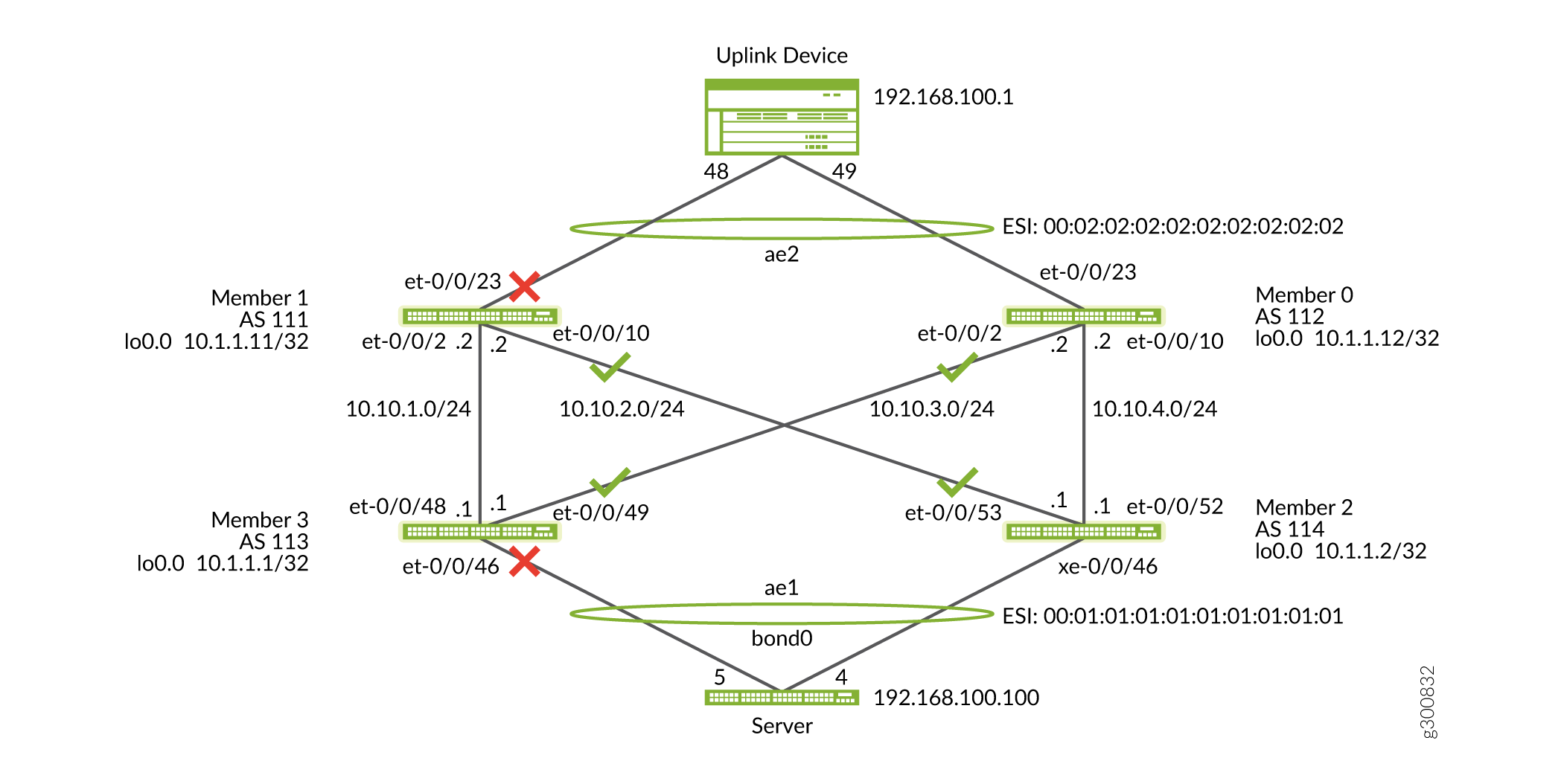
NOTE: Shutting links on the Member 1 and 3 pair and opening the link on the Member 0 and 2 pair needs to be done simultaneously as seen in Figure 8 on page 31. You can do this using scripting.
Step-by-Step Procedure
Apply the following statements on the switches and commit them at the same time. It is important to follow these
instructions.
Run commit at the same time on all devices.
There might be a slight disruption in traffic until the states converge.
Check that the traffic from the host passes successfully.
On Member 1
user@switch#set interfaces et-1/0/23 disable
user@switch#set interfaces xe-3/0/46 disable
On Member 0
user@switch>delete interfaces et-0/0/23 disable
On Member 2
user@switch>delete interfaces xe-0/0/46 disable
Migrate and Zeroize Member 1 and Member 3
Separate member 1 and member 3 by deleting the VCP between both devices. On member1 CLI apply the following commands:
user@member1> request virtual-chassis vc-port delete pic-slot 0 port 48 Member 3user@member1> request virtual-chassis vc-port delete pic-slot local 0 port 2
Step-by-Step Procedure
Now that Member 1 and 3 are isolated migrate both devices to recommended release for EVPN-VXLAN fabrics that we downloaded on all the switches at the beginning of this procedure.
Migrate the switches.
user@switch>request system software add /var/tmp/jinstall-host-qfx-5-flex-18.4R2.7-signed.tgz no-copy no-validate reboot
Zeroize the switches.
{master:0}
user@member1> request system zeroize

{master:0}
user@member3> request system zeroize
Once the switches reboot, restore the out-of-band management network connectivity.
Configure the Underlay and EVPN-VXLAN Overlay for Member 1
Follow the same procedure as for Member 0 and Member 2.

Step-by-Step Procedure
Member 1 configuration:
Configure the interfaces (keep the uplink interface for Member 1 disabled).
set interfaces et-0/0/23 disable
set interfaces et-0/0/2 unit 0 family inet address 10.10.1.2/24
set interfaces et-0/0/10 unit 0 family inet address 10.10.2.2/24
Configure the loopbacks for Member 1.
set interfaces lo0 unit 0 family inet address 10.1.1.11/32 primary
set interfaces lo0 unit 0 family inet address 10.1.1.11/32 preferred
Configure the underlay EBGP for Member 1.
set protocols bgp group underlay export VTEPS
set protocols bgp group underlay export direct
set protocols bgp group underlay local-as 111
set protocols bgp group underlay multipath multiple-as
set protocols bgp group underlay neighbor 10.10.1.1 peer-as 113
set protocols bgp group underlay neighbor 10.10.2.1 peer-as 114
Configure the overlay IBGP for Member 1.
set protocols bgp group overlay type internal
set protocols bgp group overlay local-address 10.1.1.11
set protocols bgp group overlay family evpn signaling
set protocols bgp group overlay vpn-apply-export
set protocols bgp group overlay cluster 10.1.1.11
set protocols bgp group overlay local-as 64513
set protocols bgp group overlay multipath
set protocols bgp group overlay neighbor 10.1.1.1
set protocols bgp group overlay neighbor 10.1.1.2
Configure the VLAN to VNI mapping for Member 1.
set vlans default vlan-id 1
set vlans default l3-interface irb.0
set vlans v100 vlan-id 100
set vlans v100 vxlan vni 10100
Configure the protocol EVPN-VXLAN configurations and route targets for each VNI for Member 1.
set protocols evpn vni-options vni 10100 vrf-target target:64513:100
set protocols evpn encapsulation vxlan
set protocols evpn multicast-mode ingress-replication
set protocols evpn extended-vni-list 10100
set protocols evpn extended-vni-list all
Configure the default switch options for Member 1.
set switch-options vtep-source-interface lo0.0
set switch-options route-distinguisher 10.1.1.11:1
set switch-options vrf-import my-fabric
set switch-options vrf-target target:1:9999
Configure the routing options for Member 1.
set routing-options router-id 10.1.1.11
set routing-options autonomous-system 111
set routing-options forwarding-table export LB
Configure the policies for Member 1.
set policy-options policy-statement LB then load-balance per-packet
set policy-options policy-statement VTEPS term term1 from route-filter 10.1.1.0/24 prefix-length-range /32-/32
set policy-options policy-statement VTEPS term term1 then accept
set policy-options policy-statement VTEPS term term2 then reject
set policy-options policy-statement direct term term10 from protocol direct
set policy-options policy-statement direct term term10 then accept
set policy-options policy-statement my-fabric term term1 from community my-fab-com
set policy-options policy-statement my-fabric term term1 then accept
set policy-options policy-statement my-fabric term term2 from community my-vni10100
set policy-options policy-statement my-fabric term term2 then accept
set policy-options community my-fab-com members target:1:9999
set policy-options community my-vni10100 members target:64513:100
On Member 1, configure ESI LAG to the uplink device. The ESI LAG pair for Member 1 will be Member 0 which we already configured in prior steps.
Figure 9: Configure the ESI LAG going to Member 1
set chassis aggregated-devices ethernet device-count 2
set interfaces et-0/0/23 ether-options 802.3ad ae2
set interfaces ae2 esi 00:02:02:02:02:02:02:02:02:02
set interfaces ae2 esi all-active
set interfaces ae2 aggregated-ether-options lacp active
set interfaces ae2 aggregated-ether-options lacp system-id 00:00:02:02:02:02
set interfaces ae2 unit 0 family ethernet-switching interface-mode trunk
set interfaces ae2 unit 0 family ethernet-switching vlan members v100
set interfaces em0 unit 0 family inet address 10.92.70.107/23
Configure the Underlay and EVPN-VXLAN Overlay for Member 3
Step-by-Step Procedure
Member 3 configuration:
Configure the interfaces (keep the downlink interface for Member 3 disabled).
set interfaces xe-0/0/46 disable
set interfaces et-0/0/48 unit 0 family inet address 10.10.1.1/24
set interfaces et-0/0/49 unit 0 family inet address 10.10.3.1/24
Configure the loopbacks for Member 3.
set interfaces lo0 unit 0 family inet address 10.1.1.1/32 primary
set interfaces lo0 unit 0 family inet address 10.1.1.1/32 preferred
Configure the underlay EBGP for Member 3.
set protocols bgp group underlay type external
set protocols bgp group underlay export VTEPS
set protocols bgp group underlay export direct
set protocols bgp group underlay local-as 113
set protocols bgp group underlay multipath multiple-as
set protocols bgp group underlay neighbor 10.10.1.2 peer-as 111
set protocols bgp group underlay neighbor 10.10.3.2 peer-as 112
Configure the overlay IBGP for Member 3.
set protocols bgp group overlay type internal
set protocols bgp group overlay local-address 10.1.1.1
set protocols bgp group overlay family evpn signaling
set protocols bgp group overlay vpn-apply-export
set protocols bgp group overlay local-as 64513
set protocols bgp group overlay multipath
set protocols bgp group overlay neighbor 10.1.1.11
set protocols bgp group overlay neighbor 10.1.1.12
Configure the VLAN to VNI mapping for Member 3.
set vlans default vlan-id 1
set vlans default l3-interface irb.0
set vlans v100 vlan-id 100
set vlans v100 vxlan vni 10100
Configure the protocol EVPN-VXLAN config and route targets for each VNI for Member 3.
set protocols evpn vni-options vni 10100 vrf-target target:64513:100
set protocols evpn encapsulation vxlan
set protocols evpn multicast-mode ingress-replication
set protocols evpn extended-vni-list all
Configure the default switch options for Member 3.
set switch-options vtep-source-interface lo0.0
set switch-options route-distinguisher 10.1.1.1:1
set switch-options vrf-import my-fabric
set switch-options vrf-target target:1:9999
Configure the routing options for Member 3.
set routing-options static route 0.0.0.0/0 next-hop 10.92.71.254
set routing-options router-id 10.1.1.1
set routing-options autonomous-system 113
set routing-options forwarding-table export LB
Configure the routing options for Member 3.
set policy-options policy-statement LB then load-balance per-packet
set policy-options policy-statement VTEPS term term1 from route-filter 10.1.1.0/24 prefix-length-range /32-/32
set policy-options policy-statement VTEPS term term1 then accept
set policy-options policy-statement VTEPS term term2 then reject
set policy-options policy-statement direct term term10 from protocol direct
set policy-options policy-statement direct term term10 then accept
set policy-options policy-statement my-fabric term term1 from community my-fab-com
set policy-options policy-statement my-fabric term term1 then accept
set policy-options policy-statement my-fabric term term2 from community my-vni10100
set policy-options policy-statement my-fabric term term2 then accept
set policy-options community my-fab-com members target:1:9999
set policy-options community my-vni10100 members target:64513:100
One Member 3, configure ESI LAG on the downlink to the host device. The ESI LAG pair for Member 3 will be Member 2 after Member 2 is migrated to to EVPN-VXLAN.
Figure 10: Configure the Downlink ESI LAG
set chassis aggregated-devices ethernet device-count 2
set interfaces xe-0/0/46 ether-options 802.3ad ae1
set interfaces ae1 esi 00:01:01:01:01:01:01:01:01:01
set interfaces ae1 esi all-active
set interfaces ae1 aggregated-ether-options lacp active
set interfaces ae1 aggregated-ether-options lacp system-id 00:00:01:01:01:01
set interfaces ae1 unit 0 family ethernet-switching interface-mode access
set interfaces ae1 unit 0 family ethernet-switching vlan members v100
Control Plane Convergence
At this step, we will open the links between all four member switches while keeping the uplink on Member 1 and the downlink on Member 3 disabled.
This is primarily for the convergence of BGP and EVPN-VXLAN states.
Step-by-Step Procedure
-
Check the BGP states.
user@member3> show bgp summary Threading mode: BGP I/O Groups: 2 Peers: 4 Down peers: 0 Table Tot Paths Act Paths Suppressed History Damp State Pending bgp.evpn.0 22 16 0 0 0 0 inet.0 6 4 0 0 0 0 Peer AS InPkt OutPkt OutQ Flaps Last Up/Dwn State|#Active/Received/Accepted/Damped... 10.1.1.11 64513 3164 3080 0 1 23:07:40 Establ __default_evpn__.evpn.0: 1/1/1/0 bgp.evpn.0: 11/11/11/0 default-switch.evpn.0: 10/10/10/0 10.1.1.12 64513 3053 2980 0 3 22:24:45 Establ __default_evpn__.evpn.0: 0/1/1/0 bgp.evpn.0: 5/11/11/0 default-switch.evpn.0: 5/10/10/0 10.10.1.2 111 3063 3063 0 1 23:07:44 Establ inet.0: 2/3/3/0 10.10.3.2 112 2964 2963 0 3 22:24:46 Establ inet.0: 2/3/3/0 -
EVPN-VXLAN is MAC learning through the control plane. Once the control plane information has converged on Member 1 and Member 3, enable the disabled links, which are the uplink on Member 1 and downlink on Member 3. Perform the following steps and
commitat the same time. Check for the traffic flow from the server to the uplink device.Figure 12: Open the Final Disabled Links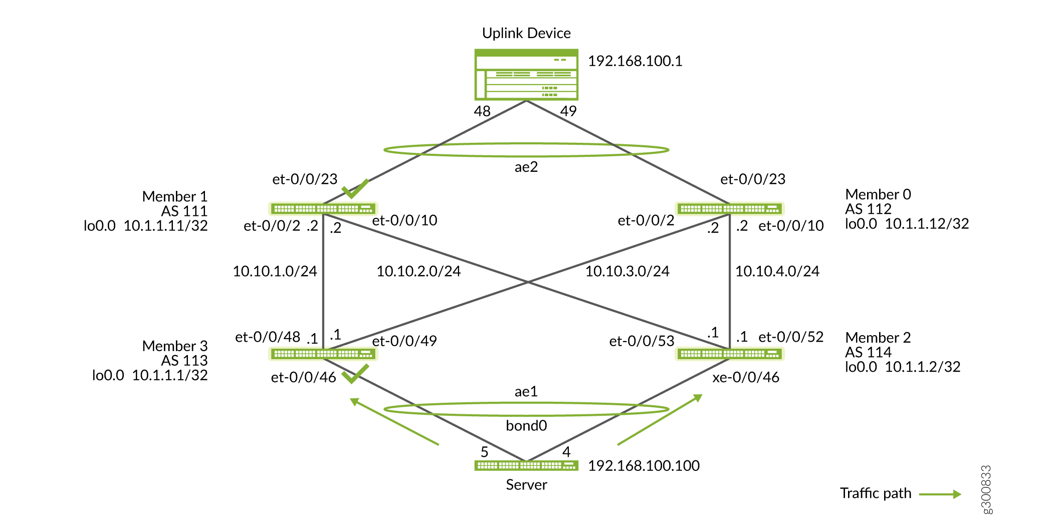
On Member 3
{master:0}[edit]
user@member3# delete interfaces xe-0/0/46 disable
On Member 1
{master:0}[edit]
user@member1# delete interfaces et-0/0/23 disable
Verification
At this point, the VCF fabric is migrated to an EVPN-VXLAN bridged overlay fabric. Perform the following check on every switch to confirm that the EVPN-VXLAN bridged overlay model is working as intended.
Step-by-Step Procedure
Check that the ESI LAGs are up and running.
user@member2> show interfaces terse | match ae
xe-0/0/46.0             up    up   aenet    --> ae1.0
ae1                     up    up
ae1.0                   up    up   eth-switch
  inet.0: 2/3/3/0
user@member2> show lacp interfaces Aggregated interface: ae1 LACP state: Role Exp Def Dist Col Syn Aggr Timeout Activity xe-0/0/46 Actor No No Yes Yes Yes Yes Fast Active xe-0/0/46 Partner No No Yes Yes Yes Yes Fast Active LACP protocol: Receive State Transmit State Mux State xe-0/0/46 Current Fast periodic Collecting distributinguser@switch> show interfaces terse | match ae et-0/0/23.0 up up aenet --> ae2.0 ae2 up up ae2.0 up up eth-switch
user@member2> show lacp interfaces
Aggregated interface: ae2
    LACP state:       Role   Exp   Def  Dist  Col  Syn  Aggr  Timeout  Activity
      et-0/0/23      Actor    No    No   Yes  Yes  Yes   Yes     Fast    Active
      et-0/0/23    Partner    No    No   Yes  Yes  Yes   Yes     Fast    Active
    LACP protocol:        Receive State  Transmit State          Mux State
      et-0/0/23                 Current   Fast periodic Collecting distributing
Check that the Ethernet switching table has a MAC entry for the host.
user@member3> show ethernet-switching table
MAC flags (S - static MAC, D - dynamic MAC, L - locally learned, P - Persistent static
           SE - statistics enabled, NM - non configured MAC, R - remote PE MAC, O - ovsdb MAC)


Ethernet switching table : 2 entries, 2 learned
Routing instance : default-switch
   Vlan                MAC                 MAC      Logical                Active
   name                address             flags    interface              source
   v100                00:1b:21:79:5a:ec   DR       ae1.0
   v100                10:0e:7e:ba:67:c0   DR       esi.1758               00:02:02:02:02:02:02:02:02:02
Check that the VLANs have VTEPS associated with them.
user@member3> show vlans
Routing instance        VLAN name             Tag          Interfaces
default-switch          default               1

default-switch          v100                  100
                                                           ae1.0*
                                                           esi.1758*
                                                           esi.1764*
                                                           vtep.32769*
                                                           vtep.32770*
                                                           vtep.32771*
Check the EVPN-VXLAN database is updated.
user@member3> show evpn database Instance: default-switch VLAN DomainId MAC address Active source Timestamp IP address 10100 00:1b:21:79:5a:ec 00:01:01:01:01:01:01:01:01:01 Aug 07 23:36:02 192.168.100.100 10100 10:0e:7e:ba:67:c0 00:02:02:02:02:02:02:02:02:02 Aug 08 21:31:49 192.168.100.1user@member3> show interfaces vtep terse Interface Admin Link Proto Local Remote vtep up up vtep.32768 up up vtep.32769 up up eth-switch vtep.32770 up up eth-switch vtep.32771 up up eth-switch
Check that the routing table is receiving type 2 and other EVPN routes.
Note:See Juniper Networks EVPN Implementation for Next-Generation Data Center Architectures for all EVPN route types.
user@switch>  show route
                       MultiRecv


bgp.evpn.0: 20 destinations, 26 routes (20 active, 0 holddown, 0 hidden)
+ = Active Route, - = Last Active, * = Both


1:10.1.1.1:0::010101010101010101::FFFF:FFFF/192 AD/ESI
                   *[EVPN/170] 22:21:54
                       Indirect
1:10.1.1.1:1::010101010101010101::0/192 AD/EVI
                   *[EVPN/170] 22:21:55
                       Indirect
1:10.1.1.2:0::010101010101010101::FFFF:FFFF/192 AD/ESI
                   *[BGP/170] 22:21:52, localpref 100, from 10.1.1.11
                      AS path: I, validation-state: unverified
                    >  to 10.10.1.2 via et-0/0/48.0
                       to 10.10.3.2 via et-0/0/49.0
                    [BGP/170] 22:21:52, localpref 100, from 10.1.1.12
                      AS path: I, validation-state: unverified
                    >  to 10.10.1.2 via et-0/0/48.0
                       to 10.10.3.2 via et-0/0/49.0
1:10.1.1.2:1::010101010101010101::0/192 AD/EVI
                   *[BGP/170] 22:21:53, localpref 100, from 10.1.1.11
                      AS path: I, validation-state: unverified
                    >  to 10.10.1.2 via et-0/0/48.0
                       to 10.10.3.2 via et-0/0/49.0
                    [BGP/170] 22:21:53, localpref 100, from 10.1.1.12
                      AS path: I, validation-state: unverified
                    >  to 10.10.1.2 via et-0/0/48.0
                       to 10.10.3.2 via et-0/0/49.0
1:10.1.1.11:0::020202020202020202::FFFF:FFFF/192 AD/ESI
                   *[BGP/170] 23:06:44, localpref 100, from 10.1.1.11
                      AS path: I, validation-state: unverified
                    >  to 10.10.1.2 via et-0/0/48.0
1:10.1.1.11:1::020202020202020202::0/192 AD/EVI
                   *[BGP/170] 23:06:45, localpref 100, from 10.1.1.11
                      AS path: I, validation-state: unverified
                    >  to 10.10.1.2 via et-0/0/48.0
1:10.1.1.12:0::020202020202020202::FFFF:FFFF/192 AD/ESI
                   *[BGP/170] 22:23:49, localpref 100, from 10.1.1.12
                      AS path: I, validation-state: unverified
                    >  to 10.10.3.2 via et-0/0/49.0
1:10.1.1.12:1::020202020202020202::0/192 AD/EVI
                   *[BGP/170] 22:23:50, localpref 100, from 10.1.1.12
                      AS path: I, validation-state: unverified
                    >  to 10.10.3.2 via et-0/0/49.0
2:10.1.1.2:1::10100::00:1b:21:79:5a:ec/304 MAC/IP
                   *[BGP/170] 21:57:58, localpref 100, from 10.1.1.11
                      AS path: I, validation-state: unverified
                       to 10.10.1.2 via et-0/0/48.0
                    >  to 10.10.3.2 via et-0/0/49.0
                    [BGP/170] 21:57:58, localpref 100, from 10.1.1.12
                      AS path: I, validation-state: unverified
                       to 10.10.1.2 via et-0/0/48.0
                    >  to 10.10.3.2 via et-0/0/49.0
2:10.1.1.11:1::10100::10:0e:7e:ba:67:c0/304 MAC/IP
                   *[BGP/170] 00:25:28, localpref 100, from 10.1.1.11
                      AS path: I, validation-state: unverified
                    >  to 10.10.1.2 via et-0/0/48.0
2:10.1.1.12:1::10100::10:0e:7e:ba:67:c0/304 MAC/IP
                   *[BGP/170] 00:02:11, localpref 100, from 10.1.1.12
                      AS path: I, validation-state: unverified
                    >  to 10.10.3.2 via et-0/0/49.0
2:10.1.1.2:1::10100::00:1b:21:79:5a:ec::192.168.100.100/304 MAC/IP
                   *[BGP/170] 21:57:58, localpref 100, from 10.1.1.11
                      AS path: I, validation-state: unverified
                       to 10.10.1.2 via et-0/0/48.0
                    >  to 10.10.3.2 via et-0/0/49.0
                    [BGP/170] 21:57:58, localpref 100, from 10.1.1.12
                      AS path: I, validation-state: unverified
                       to 10.10.1.2 via et-0/0/48.0
                    >  to 10.10.3.2 via et-0/0/49.0
2:10.1.1.11:1::10100::10:0e:7e:ba:67:c0::192.168.100.1/304 MAC/IP
                   *[BGP/170] 00:25:28, localpref 100, from 10.1.1.11
                      AS path: I, validation-state: unverified
                    >  to 10.10.1.2 via et-0/0/48.0
2:10.1.1.12:1::10100::10:0e:7e:ba:67:c0::192.168.100.1/304 MAC/IP
                   *[BGP/170] 00:02:11, localpref 100, from 10.1.1.12
                      AS path: I, validation-state: unverified
                    >  to 10.10.3.2 via et-0/0/49.0
3:10.1.1.1:1::10100::10.1.1.1/248 IM
                   *[EVPN/170] 21:57:59
                       Indirect
3:10.1.1.2:1::10100::10.1.1.2/248 IM
                   *[BGP/170] 21:57:58, localpref 100, from 10.1.1.11
                      AS path: I, validation-state: unverified
                    >  to 10.10.1.2 via et-0/0/48.0
                       to 10.10.3.2 via et-0/0/49.0
                    [BGP/170] 21:57:58, localpref 100, from 10.1.1.12
                      AS path: I, validation-state: unverified
                    >  to 10.10.1.2 via et-0/0/48.0
                       to 10.10.3.2 via et-0/0/49.0
3:10.1.1.11:1::10100::10.1.1.11/248 IM
                   *[BGP/170] 21:57:58, localpref 100, from 10.1.1.11
                      AS path: I, validation-state: unverified
                    >  to 10.10.1.2 via et-0/0/48.0
3:10.1.1.12:1::10100::10.1.1.12/248 IM
                   *[BGP/170] 02:49:58, localpref 100, from 10.1.1.12
                      AS path: I, validation-state: unverified
                    >  to 10.10.3.2 via et-0/0/49.0
4:10.1.1.1:0::010101010101010101:10.1.1.1/296 ES
                   *[EVPN/170] 22:21:55
                       Indirect
4:10.1.1.2:0::010101010101010101:10.1.1.2/296 ES
                   *[BGP/170] 22:21:53, localpref 100, from 10.1.1.11
                      AS path: I, validation-state: unverified
                    >  to 10.10.1.2 via et-0/0/48.0
                       to 10.10.3.2 via et-0/0/49.0
                    [BGP/170] 22:21:53, localpref 100, from 10.1.1.12
                      AS path: I, validation-state: unverified
                    >  to 10.10.1.2 via et-0/0/48.0
                       to 10.10.3.2 via et-0/0/49.0


default-switch.evpn.0: 17 destinations, 22 routes (17 active, 0 holddown, 0 hidden)
+ = Active Route, - = Last Active, * = Both

1:10.1.1.1:1::010101010101010101::0/192 AD/EVI
                   *[EVPN/170] 22:21:55
                       Indirect
1:10.1.1.2:0::010101010101010101::FFFF:FFFF/192 AD/ESI
                   *[BGP/170] 22:21:52, localpref 100, from 10.1.1.11
                      AS path: I, validation-state: unverified
                    >  to 10.10.1.2 via et-0/0/48.0
                       to 10.10.3.2 via et-0/0/49.0
                    [BGP/170] 22:21:52, localpref 100, from 10.1.1.12
                      AS path: I, validation-state: unverified
                    >  to 10.10.1.2 via et-0/0/48.0
                       to 10.10.3.2 via et-0/0/49.0
1:10.1.1.2:1::010101010101010101::0/192 AD/EVI
                   *[BGP/170] 22:21:53, localpref 100, from 10.1.1.11
                      AS path: I, validation-state: unverified
                    >  to 10.10.1.2 via et-0/0/48.0
                       to 10.10.3.2 via et-0/0/49.0
                    [BGP/170] 22:21:53, localpref 100, from 10.1.1.12
                      AS path: I, validation-state: unverified
                    >  to 10.10.1.2 via et-0/0/48.0
                       to 10.10.3.2 via et-0/0/49.0
1:10.1.1.11:0::020202020202020202::FFFF:FFFF/192 AD/ESI
                   *[BGP/170] 23:06:44, localpref 100, from 10.1.1.11
                      AS path: I, validation-state: unverified
                    >  to 10.10.1.2 via et-0/0/48.0
1:10.1.1.11:1::020202020202020202::0/192 AD/EVI
                   *[BGP/170] 23:06:45, localpref 100, from 10.1.1.11
                      AS path: I, validation-state: unverified
                    >  to 10.10.1.2 via et-0/0/48.0
1:10.1.1.12:0::020202020202020202::FFFF:FFFF/192 AD/ESI
                   *[BGP/170] 22:23:49, localpref 100, from 10.1.1.12
                      AS path: I, validation-state: unverified
                    >  to 10.10.3.2 via et-0/0/49.0
1:10.1.1.12:1::020202020202020202::0/192 AD/EVI
                   *[BGP/170] 22:23:50, localpref 100, from 10.1.1.12
                      AS path: I, validation-state: unverified
                    >  to 10.10.3.2 via et-0/0/49.0
2:10.1.1.2:1::10100::00:1b:21:79:5a:ec/304 MAC/IP
                   *[BGP/170] 21:57:58, localpref 100, from 10.1.1.11
                      AS path: I, validation-state: unverified
                       to 10.10.1.2 via et-0/0/48.0
                    >  to 10.10.3.2 via et-0/0/49.0
                    [BGP/170] 21:57:58, localpref 100, from 10.1.1.12
                      AS path: I, validation-state: unverified
                       to 10.10.1.2 via et-0/0/48.0
                    >  to 10.10.3.2 via et-0/0/49.0
2:10.1.1.11:1::10100::10:0e:7e:ba:67:c0/304 MAC/IP
                   *[BGP/170] 00:25:28, localpref 100, from 10.1.1.11
                      AS path: I, validation-state: unverified
                    >  to 10.10.1.2 via et-0/0/48.0
2:10.1.1.12:1::10100::10:0e:7e:ba:67:c0/304 MAC/IP
                   *[BGP/170] 00:02:11, localpref 100, from 10.1.1.12
                      AS path: I, validation-state: unverified
                    >  to 10.10.3.2 via et-0/0/49.0
2:10.1.1.2:1::10100::00:1b:21:79:5a:ec::192.168.100.100/304 MAC/IP
                   *[BGP/170] 21:57:58, localpref 100, from 10.1.1.11
                      AS path: I, validation-state: unverified
                       to 10.10.1.2 via et-0/0/48.0
                    >  to 10.10.3.2 via et-0/0/49.0
                    [BGP/170] 21:57:58, localpref 100, from 10.1.1.12
                      AS path: I, validation-state: unverified
                       to 10.10.1.2 via et-0/0/48.0
                    >  to 10.10.3.2 via et-0/0/49.0
2:10.1.1.11:1::10100::10:0e:7e:ba:67:c0::192.168.100.1/304 MAC/IP
                   *[BGP/170] 00:25:28, localpref 100, from 10.1.1.11
                      AS path: I, validation-state: unverified
                    >  to 10.10.1.2 via et-0/0/48.0
2:10.1.1.12:1::10100::10:0e:7e:ba:67:c0::192.168.100.1/304 MAC/IP
                   *[BGP/170] 00:02:11, localpref 100, from 10.1.1.12
                      AS path: I, validation-state: unverified
                    >  to 10.10.3.2 via et-0/0/49.0
3:10.1.1.1:1::10100::10.1.1.1/248 IM
                   *[EVPN/170] 22:21:53
                       Indirect
3:10.1.1.2:1::10100::10.1.1.2/248 IM
                   *[BGP/170] 21:57:58, localpref 100, from 10.1.1.11
                      AS path: I, validation-state: unverified
                    >  to 10.10.1.2 via et-0/0/48.0
                       to 10.10.3.2 via et-0/0/49.0
                    [BGP/170] 21:57:58, localpref 100, from 10.1.1.12
                      AS path: I, validation-state: unverified
                    >  to 10.10.1.2 via et-0/0/48.0
                       to 10.10.3.2 via et-0/0/49.0
3:10.1.1.11:1::10100::10.1.1.11/248 IM
                   *[BGP/170] 21:57:58, localpref 100, from 10.1.1.11
                      AS path: I, validation-state: unverified
                    >  to 10.10.1.2 via et-0/0/48.0
3:10.1.1.12:1::10100::10.1.1.12/248 IM
                   *[BGP/170] 02:49:58, localpref 100, from 10.1.1.12
                      AS path: I, validation-state: unverified
                    >  to 10.10.3.2 via et-0/0/49.0

__default_evpn__.evpn.0: 3 destinations, 4 routes (3 active, 0 holddown, 0 hidden)
+ = Active Route, - = Last Active, * = Both


1:10.1.1.1:0::010101010101010101::FFFF:FFFF/192 AD/ESI
                   *[EVPN/170] 22:21:54
                       Indirect
4:10.1.1.1:0::010101010101010101:10.1.1.1/296 ES
                   *[EVPN/170] 22:21:55
                       Indirect
4:10.1.1.2:0::010101010101010101:10.1.1.2/296 ES
                   *[BGP/170] 22:21:53, localpref 100, from 10.1.1.11
                      AS path: I, validation-state: unverified
                    >  to 10.10.1.2 via et-0/0/48.0
                       to 10.10.3.2 via et-0/0/49.0
                    [BGP/170] 22:21:53, localpref 100, from 10.1.1.12
                      AS path: I, validation-state: unverified
                    >  to 10.10.1.2 via et-0/0/48.0
                       to 10.10.3.2 via et-0/0/49.0
Conclusion
This procedure outlines a step-by-step recommended method to migrate a centralized control plane VCF fabric to a distributed control plane Bridged overlay EVPN-VXLAN fabric.