Gateway Functionality and Virtual Network Traffic Technical Overview
Layer 3 gateway functionality has evolved over time and had some differences in its supported features and operations. There are two methods to configure Layer 3 gateway functionality on a Junos OS device:
Configure integrated routing and bridging (IRB) interfaces directly and advertise these as gateway addresses.
Configure an IRB interface and a virtual gateway address (used as the default IPv4 or IPv6 address for the gateway) to support the IRB interface redundant gateway function.
The following functionality is supported for traffic between virtual networks:
Layer 3 Default Gateway Functionality
There are two configuration methods because initially when Ethernet VPN (EVPN) and Layer 3 gateway functionality were first conceived, RFC 7209, Requirements for Ethernet VPN (EVPN) had to be adhered to. All provider edge (PE) devices for an EVPN instance must have an IRB configured.
EVPN-Virtual Extensible LAN protocol (VXLAN) optimizes forwarding decisions within the network based on the Layer 2 MAC address, as well as the Layer 3 IP address information. The decision on forwarding (by routing or switching) should be made at the leaf layer on the top-of-rack (ToR) switch. However, QFX5100 switches (the current typical choice for the leaf layer) only provide intrasubnet (Layer 2) capabilities; they cannot provide intersubnet (Layer 3) routing. As a result, you must implement endpoint (or end host) gateway redundancy at the spine layer.
MX Series routers provide Layer 3 default gateway functionality for endpoints through their IRB interface, enabling intersubnet forwarding between virtual machines (VMs) or bare-metal servers (BMS). Figure 1 shows an example of an MX Series router providing Layer 3 gateway functionality at the spine layer of the network.
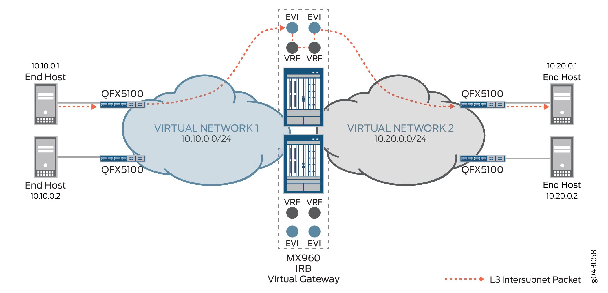
To provide the default gateway function, each IRB interface is assigned two sets of addresses: an IP/MAC address pair that is unique to the device, and a common virtual gateway IP address and virtual MAC address pair to use across all gateway devices.
When you configure the IRB interface, think of the IP address as having two separate parts:
A unique part (IRB interface IP address)
An anycast part (IRB virtual gateway IP address)
Note:You can consider the virtual gateway IP address essentially as the anycast IP address used by a group of redundant MX Series routers. The maximum number of provider edge (PE) devices that can have the same virtual gateway IP address is 64.
Configuring end hosts on your network with static default routes minimizes configuration effort and complexity and reduces processing overhead on the end hosts. However, when you configure end hosts with static routes, the failure of the default gateway normally results in a catastrophic event, isolating all hosts that are unable to detect available alternate paths to their gateway. By using the anycast IP and MAC addresses, you enable default gateway redundancy functionality and ensure that end hosts have continual intersubnet reachability.
The virtual gateway IP address is used as the default gateway IP address by either the end host or VM attached to the bridge domain. You configure each end host or VM to use the MX Series router’s anycast IP address as its default gateway. By using the anycast IP address as the default gateway address, when a VM moves from one place in the network to another, the moved VM can use the same default gateway and does not have to update its default gateway IP address for MAC binding.
For ARP requests and pings initiated by the MX Series router gateway, the IRB’s unique interface IP address is used as the source IP address.
- MX Series Router as the Default Gateway for Known Intersubnet Traffic Between Virtual Networks
- MX Series Router as the Default Gateway for Unknown Intersubnet Traffic Between Virtual Networks
MX Series Router as the Default Gateway for Known Intersubnet Traffic Between Virtual Networks
Figure 2 shows known intersubnet traffic between virtual networks.
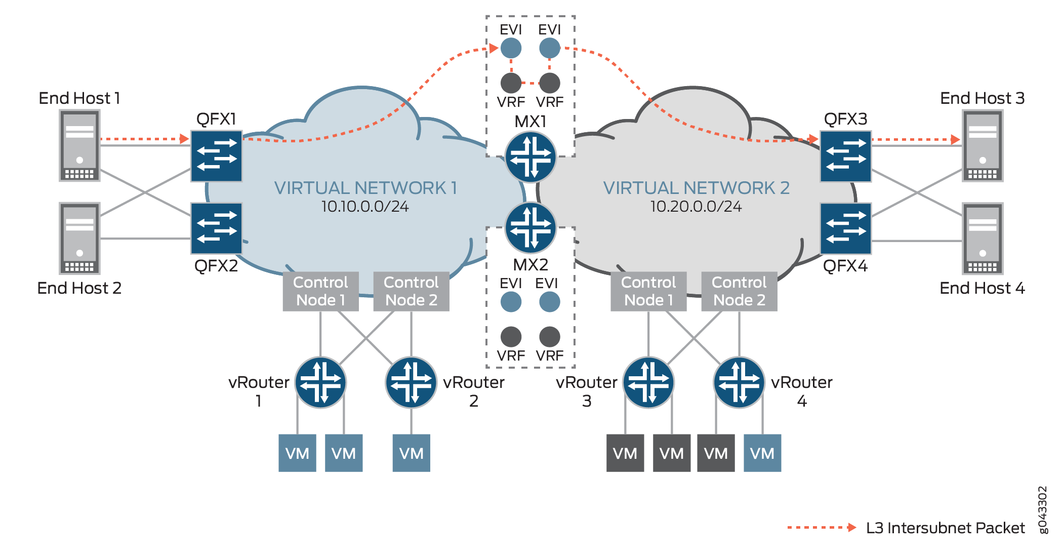
For known intersubnet traffic between virtual networks that originated from End Host 1 in virtual network 1 (10.10.0.0/24) destined for End Host 3 in virtual network 2 (10.20.0.0/24), End Host 1 first sends the packet to QFX1 to encapsulate the data. QFX1 then sends the VXLAN-encapsulated packet to MX1’s table, with its inner destination MAC address set to the MX1’s IRB interface and its inner destination IP address (DIP) set to End Host 3. As MX1 de-encapsulates the packet, it discovers that the destination MAC address is that of its own IRB interface, and sends the packet to be routed in the L3-VRF routing table. After performing a route lookup, the packet is routed to virtual network 2, and then based on the ARP route entry, MX1 re-encapsulates the packet with VXLAN information and forwards it to QFX3. QFX3 de-encapsulates the packet once more, and performs a table look up to send the packet to End Host 3 as its final destination.
For this example, it is assumed that the QFX Series switches in Figure 2 are all QFX5100 devices, that are, Layer 2 gateway devices which do not provide Layer 3 gateway functionality.
MX Series Router as the Default Gateway for Unknown Intersubnet Traffic Between Virtual Networks
For unknown intersubnet traffic between virtual networks initiated from the end host, an additional ARP request and response process is required at the MX Series router gateway. When the packet is received at the MX Series router gateway, the gateway sends an ARP request for the destination End Host 3’s IP address and the MAC address binding. After destination MAC plus IP binding for the end station is resolved, the traffic flows follow the same procedure as described previously for the known intersubnet forwarding process.
Virtual Gateway Load Balancing and Failover
EVPN all-active multihoming provides gateway redundancy and load balancing by associating all of the IRB interface’s virtual gateway MAC and IP addresses for a given virtual network with the same Ethernet segment ID. Each MX Series gateway router advertises the virtual gateway MAC and IP addresses through the EVPN Type 2 route. Additionally, each MX Series router also advertises an EVPN Type 1 Ethernet segment Auto-Discovery (A-D) route to announce the Ethernet segment. For more information about Type 1 and Type 2 routes, refer to RFC 7432, BGP MPLS-Based Ethernet VPN.
Other EVPN-enabled devices consider the virtual MAC address as multihomed to the MX Series routers. Using the standard EVPN all-active process, a remote EVPN PE device can now build an equal-cost multipath (ECMP) next hop to reach the IRB’s virtual MAC address or anycast IP address based on the route advertised by each MX Series gateway router. Traffic destined to the IRB’s virtual gateway MAC is load balanced across all MX Series routers.
If one of the MX Series gateways has a node failure, all of the remote EVPN PE devices are notified by the withdrawing, or purging of the IRB’s virtual gateway MAC route advertised by the failed MX Series gateway. As a result, all remote EVPN PE devices update their next hops to reach the IRB’s virtual gateway MAC address or anycast IP address to exclude the path to the failed gateway. Because the IRB’s virtual MAC and anycast IP addresses are still reachable through the updated next hop, and the binding of the virtual MAC address to the anycast IP address remains the same, no changes are made to the ARP entries on the end hosts attached to the remote EVPN PE devices.