Migration from Cisco Wireless to Juniper Mist Wireless
Explore the different options for migration from legacy controller-based architecture to Juniper Mist.
This document is intended for network architects and engineers planning or executing migrations from Cisco wireless networks to Juniper Mist in production campus environments.
To initiate the migration process, the first step is to assess the user's existing network along with the requirements for the new environment. Once these requirements are clearly defined, the next step is to design the new network architecture. The final phase involves developing a detailed migration plan—selecting a specific area for evaluation, conducting a pilot deployment, and then transitioning the design into full production.
Migration Options
Unlike traditional wireless deployments that require a dedicated wireless LAN controller (WLC)—such as the AireOS —to manage access points (APs), Juniper Mist APs are managed directly through the Mist portal. This approach enables users to centrally manage and monitor their wireless networks across multiple sites from a single cloud application.
Distributed Data Plane or Local Switching
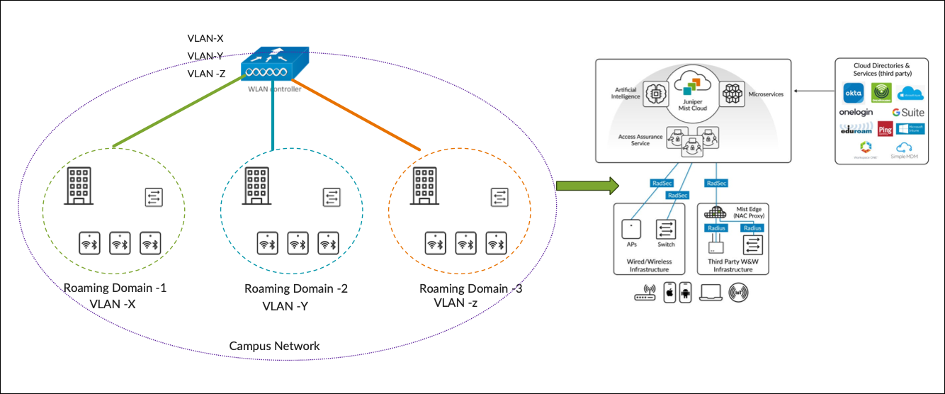
In a large campus network, use a distributed data plane approach where the Mist APs locally switch all the wireless traffic to the rest of the network. This model is similar to a FlexConnect deployment using Cisco AireOS.
A key advantage of the distributed data plane approach is its ability to meet the throughput requirements of Wi-Fi standards, such as Wi-Fi 6E and future iterations, since each AP handles and forwards its own traffic locally rather than relying on a centralized controller.
The combination of a distributed data plane and cloud-based network management significantly reduces the amount of equipment deployed. In most cases, a WLC is unnecessary as all the network devices can be managed and monitored through the Mist portal.
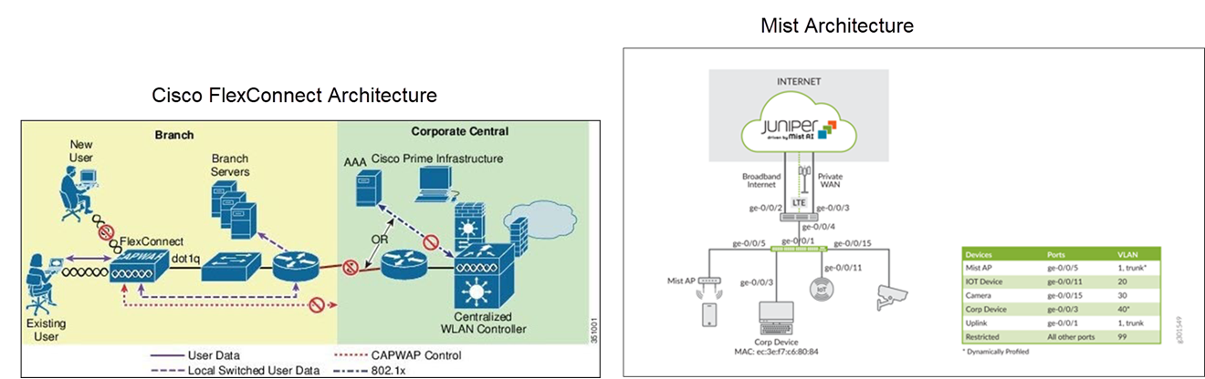
Here's an example illustrating the migration from a Cisco FlexConnect deployment (local switching).
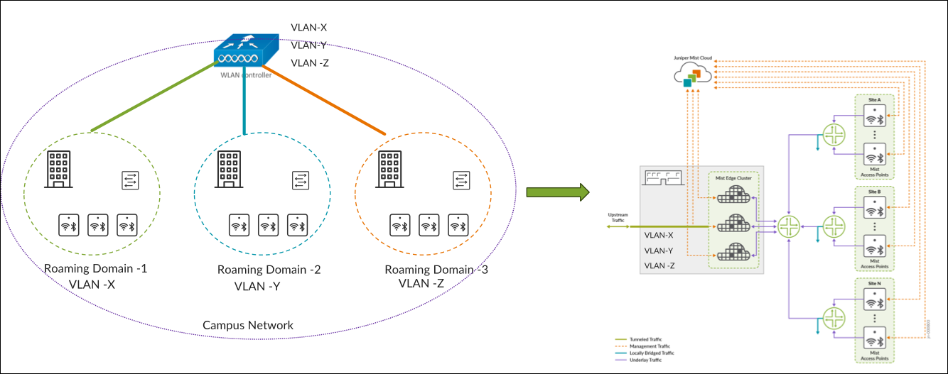
Centralized Data Plane
In a controller-based deployment from Cisco, Wi-Fi client traffic is encapsulated in a CAPWAP or GRE tunnel between the AP and a controller. As traffic from an endpoint reaches the AP over its radio interface, it is encapsulated and forwarded through the wired LAN to the controller. The controller then inspects the traffic, tags it, and forwards it on a local interface to a trunked user VLAN.
In deployments that retain a centralized data path, we replace the WLC with a Mist Edge device. Traffic is tunnelled from the AP to the Mist Edge. APs can load-balance the traffic across Mist Edges in the primary cluster. See Figure 1.
Switching Architecture Guidelines
Guidelines for Access Switch Ports
When designing the underlying switching architecture, follow these recommendations for the access switch ports connected to APs:
- Configure the ports as trunk ports to enable APs to pass multiple VLANs when
switching wireless traffic to the wired network.
- Ensure that the VLANs for AP management traffic and each broadcasted SSID are permitted on the port.
- For zero-touch provisioning of the AP, designate the native VLAN on the trunk port as the management VLAN for the APs.
-
Configure the ports with Spanning Tree Portfast Trunk, BPDU guard, and Root guard.
If wired clients are connected to the same switch, the VLANs associated with the wired clients should be confined to that specific access switch (see the following example). VLANs associated with the wireless clients should span across all the access switches that are within the roaming domain.
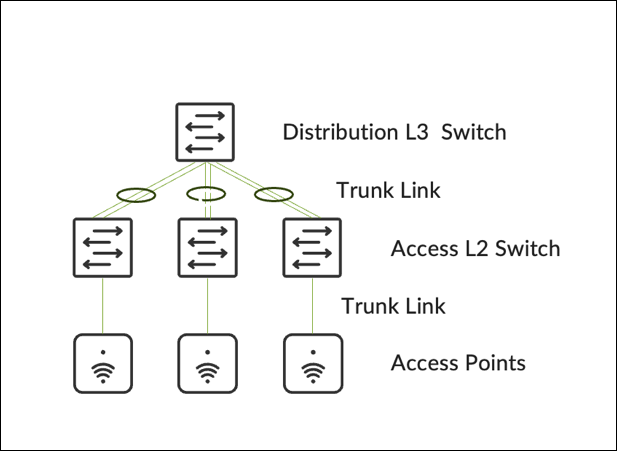
Guidelines for Distibution Layer Switches
For distribution layer switches, configure the switches either as a Virtual Chassis/Stack or using HSRP/VRRP for redundancy.
-
A Virtual Chassis or stacking architecture provides distribution‑layer redundancy without intentional Layer 2 loops.
-
Configure the uplinks from access switches to the distribution switch as trunk ports with EtherChannel.
-
Limit the allowed VLANs on trunk ports to only those necessary.
-
-
HSRP or VRRP provides first-hop redundancy
-
Configure the STP Root and HSRP primary on the same switch.
-
Configure uplinks from access switches as trunk ports with EtherChannel.
-
Implement BPDU and Root Guard on downlinks, and Loop Guard on uplinks.
-
Allow only essential VLANs on trunks leading to the distribution layer.
-
Ensure VLANs used by wireless clients for WLAN connections are permitted on trunks between the distribution layer and all access switches that are part of the roaming domain.
-
Be aware of potential asymmetric traffic issues due to differences between the virtual MAC address and the physical MAC address of interfaces, which might affect captive portal redirection. To mitigate such issues, we recommended using a single gateway MAC address.
-
Roaming Domain
A roaming domain is an RF continuity area in which a client can remain connected to the same SSID while moving within the domain. A roaming domain can span across multiple physical or virtual domains where users require fast and seamless roaming to maintain connectivity for their applications.
Seamless roaming ensures that a client retains its IP address and policy as it roams across different APs.
A fast roam occurs when a client does not need to re-authenticate every time it roams to a new AP. To enable both fast and secure roaming, the Pairwise Master Key (PMK)—derived during the initial authentication—must be consistent and shared across the roaming domain. Key sharing allows clients to move between APs with minimal delays, usually under 50ms. You can enable key caching protocols, like 802.11r or OKC, which must also be supported by clients. For additional optimization, networks can leverage 802.11k or 802.11v.
Roaming domains can span groups of floors, a single building, or multiple buildings. The physical or virtual groupings chosen for a roaming domain determine how APs are organized within the Mist portal. Within the Mist portal, two main management design constructs define how networks are managed:
- Organization: A collection of sites that are part of a single organization
- Sites: A group of devices that are typically mapped to a geographical location such as sites, groups of buildings, buildings, or floors.
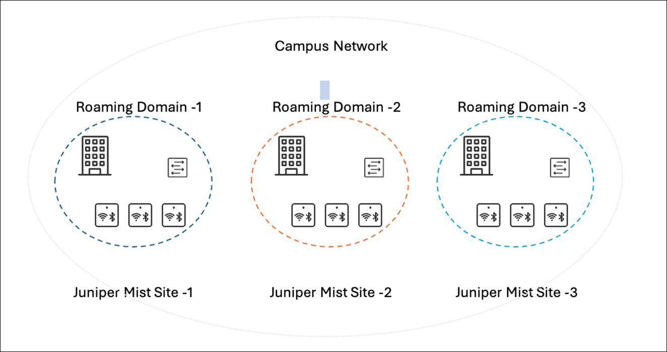
Because of this design, it is essential to plan the roaming domains such that they divide the campus’s physical locations with clear RF boundaries. This structuring ensures that clients roam among APs within the same roaming domains. Examples of how to find these divisions can be:
- Geographical Areas: Identify logical divisions within a campus that can be easily delineated. For example, areas like North, South, East, and West wings typically represent significant physical boundaries and are suitable choices for separate roaming domains.
- Outdoor Wireless: Group outdoor wireless areas with the buildings they are adjacent to.
It is recommended to segment the campus by building as the smallest roaming domain. This helps avoid RF leakage between floors, leading to client devices possibly connecting to APs on different floors. Otherwise, clients might experience hard roams within the same building.
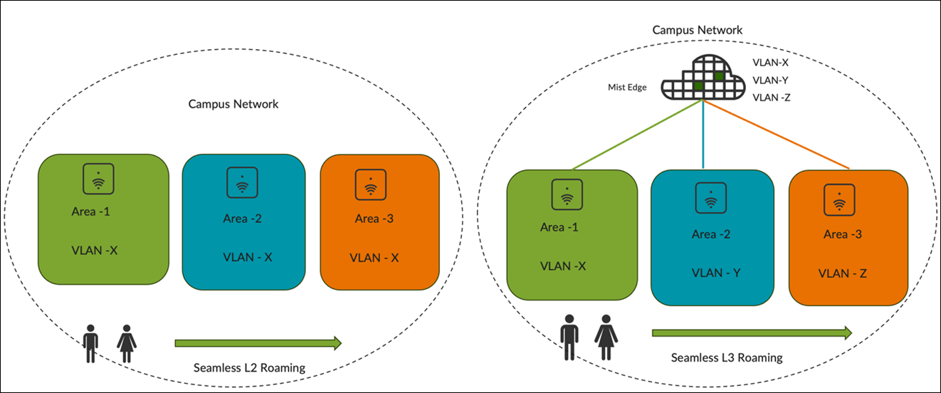
When determining the roaming domain size, it is essential to understand whether clients will use Layer 2 (L2) or Layer 3 (L3) roaming. as the choice will significantly impact the roaming domain's sizing due to the underlying switching architecture.
- L2 Roaming occurs when a client roams between APs that broadcast the same
SSID and are associated with the same VLAN. Because the client remains on the
same subnet, it keeps its existing IP address resulting in both seamless and
fast roaming.
When a client roams to an AP where the same WLAN is associated with a different VLAN, the subnet changes. This disrupts the existing session and necessitates the client to go through DHCP renewal, which can take several seconds.
- L3 Roaming occurs when clients roam to an AP where the same WLAN is associated with a different VLAN. However, a mechanism such as tunneling or re-anchoring to the original AP enables the client to retain its IP address, ensuring seamless roaming.
However, enabling L2 roaming with the same VLAN for the WLAN necessitates extending the VLAN across all access switches within the roaming domain, possibly spanning multiple wiring closets or even multiple buildings. Depending on the number of devices in the roaming domain, a large subnet might be needed for the VLAN, resulting in a large broadcast domain.
The size of the VLAN is influenced by the types of Layer 2 and Layer 3 switches deployed at the site. Factors such as MAC address and ARP table scale, CPU impact from spanning tree operations, client scale, and DHCP scope design directly affect the size of the VLAN that can be deployed. Follow established best practices when designing the access network.
It’s recommended to assign separate VLANs or subnets to each roaming domain in addition to establishing RF boundaries. Doing so confines the broadcast domain to the size of the roaming domain, reducing the impact of traffic such as broadcast, unknown unicast, and multicast (BUM) traffic. This approach also reduces faults and security threats (such as TCAM/ARP attacks and broadcast storms) and simplifies management as it is easier to locate clients by their VLAN or subnet.
Key Considerations for Migration to Mist
The following steps reflect commonly observed best practices from customer deployments. Specific migration sequences may vary based on network design, client behavior, and operational constraints.
-
Conduct a site survey to select the appropriate APs and antennas.
-
Retain the existing switch port configuration for the AP (for centralized designs).
-
Define a roaming domain that ensures seamless roaming.
-
Establish RADIUS integration for client authentication.
-
Replace APs in stages and take advantage of the 6 GHz band wherever available.
-
Disable fast roaming, rogue AP, mitigation and channel planning on the installed Cisco base.
-
Validate that the client performance remains acceptable.
-
Identify an area that is small enough to be changed in a single change window with minimal crossover—a mezzanine floor for example.
-
Deploy Juniper APs with the same reduced functionality around roaming but keep channel planning on.
-
Test all client types roaming in and out of the area while performing real-time picking tasks.
-
Define an acceptable failure rate to validate feasibility of a phased approach for rollout.
-
-
Test and validate the roaming points at each stage to ensure that they meet the agreed thresholds.
-
Determine Mist Edge requirements after all the APs are migrated.
If Mist Edges are required:
-
Install a pair of Mist Edges alongside Cisco controllers.
-
Map client SSIDs to the same VLANs.
-
Retain the existing access switch configuration.
If Mist Edges are not required, reconfigure edge switches for local breakout.
-
-
Enable fast roaming and rogue AP management features on the Juniper Mist portal
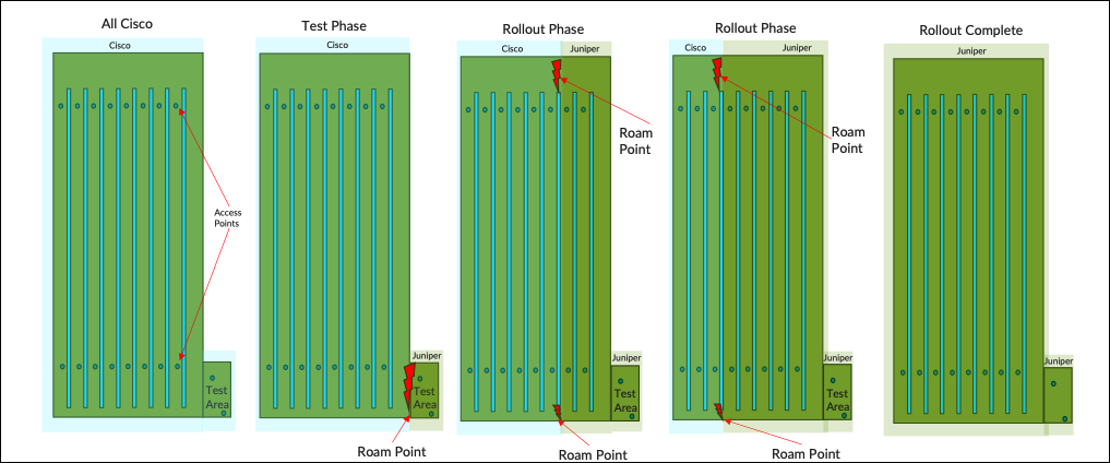
The following simulation illustrates how the rollout is intended to progress under ideal conditions,
Architecture Migration of Cisco Wireless (AireOS) to Juniper Mist
- Migration from Cisco Centralized Wireless Architecture to Mist
- Migration from Cisco FlexConnect Wireless Architecture to Mist
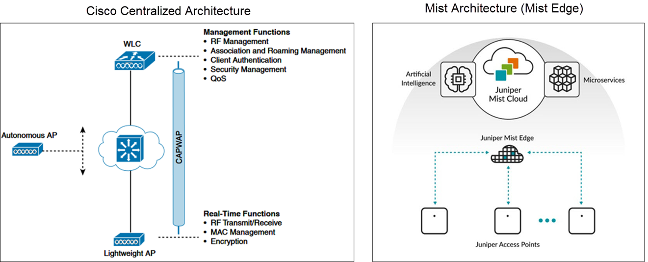
Migration from Cisco Centralized Wireless Architecture to Mist
In the Cisco centralized architecture deployment, management functions are typically handled by a WLC, which manages many lightweight APs. These APs operate in Lightweight AP mode, meaning they rely on a WLC to carry out management tasks.
The Mist solution utilizes the Mist Edge for cases that need to retain the centralized datapath architecture for campus branch deployments. The solution provides the same level of redundancy and access to corporate resources, while extending visibility into user network experiences and streamlining IT operations. The Mist APs can establish L2TPv3 tunnels to extend one or more VLANs from one or multiple Mist Edges located in the Campus, DC, or DMZ simultaneously. The Mist APs can support both local and centralized datapath at the same time.
Migration from Cisco FlexConnect Wireless Architecture to Mist
FlexConnect is a wireless solution for branch office and remote office deployments. This solution enables deployment and configuration of APs at remote branches across the WAN link while the controller is placed at a central location. The FlexConnect APs can locally switch client data and perform client authentication. When the APs are connected to the controller, they can also send traffic back to the controller.
Juniper Mist Wireless Assurance automates troubleshooting and operations, providing predictable, reliable and measurable wireless performance with near-real-time visibility into user service levels.