Configure Campus Fabric EVPN Multihoming
Follow these steps to merge the core and distribution layers into a single switch by configuring EVPN multihoming.
The Juniper Networks campus fabrics EVPN multihoming solution supports a collapsed core architecture. This architecture merges the core and distribution layers into a single switch. Merging these layers into a single switch turns the traditional three-tier hierarchical network into a two-tiered network. This architecture also eliminates the need for STP across campus networks by providing multihoming capabilities from the access layer to the core layer.
-
The topology type EVPN Multihoming is available only for the site-specific campus fabric. You cannot build it at the organization level.
-
In topologies that are built in Mist cloud after the May 2025 updates, Mist automatically detects and reports any EVPN loops and duplicate MAC addresses. These issues are displayed on the switch Insights page.
-
EVPN loop detection—EVPN-VXLAN lightweight PE-CE loop detection helps in detecting and breaking LAN Ethernet loops on downstream leaf-to-server or access ports. This feature can detect loops caused by issues such as miswired fabric components or third-party switches incorrectly connected to the fabric.For this feature to work, the switch must run the Junos OS version 24.4R1 or later. For more information, refer to EVPN-VXLAN Lightweight Leaf to Server Loop Detection.
-
Duplicate MAC address detection—Identifies and mitigates issues arising from MAC address movement (MAC mobility) between different interfaces or devices in EVPN environments. While some MAC mobility is expected (for example, when a device actually moves), rapid changes might indicate issues such as network loops or misconfigurations. For more information, refer to Configuring Loop Detection for Duplicate MAC Addresses.
-
Duplicate VLAN IDs —Detects loops in the fabric of non‑core switches caused by overlapping VLAN IDs on the EVPN overlay and the underlay (for example, on AP trunk ports). The overlap can create a parallel Layer‑2 forwarding path, causing bridging loops, broadcast storms, and service degradation, especially when AP traffic is tunneled into Mist Edge. The event is visible on the Insights page as Fabric Loop Detected.
-
For a detailed configuration example, see Campus Fabric EVPN Multihoming Workflow.
Campus Fabric Configuration Best Practices
- Configure VLANs at switch template level and import them while configuring campus fabric. Template must be the single source of truth for all VLANs and port profiles unless specifically required at the switch or site level.
- At the access layer, avoid using trunk port profiles that allow all VLANs, unless explicitly required.
- Create VRF and VRF network configuration via the campus fabric, not via switch templates.
- Create port assignments per role and overwrite the configuration on individual device as needed.
- Manage the DHCP relay configuration via the campus fabric workflow, except for the service block devices.
To configure campus fabric EVPN multihoming:
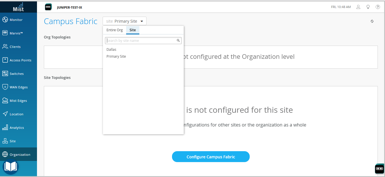
- From the left navigation menu, select Organization > Campus Fabric.
-
From the site drop-down list beside the page heading, select the site where you want to
build the campus fabric.
-
Click whichever option is relevant. Click:
-
the Configure Campus Fabric button (displayed if the site doesn't have a campus fabric configuration associated with it).
-
the Create Campus Fabric button (displayed if the site already has at least one campus fabric configuration associated with it).
The Topology tab is displayed. -
-
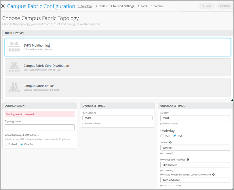
Select the topology type EVPN Multihoming.
-
Configure the remaining settings on the Topology tab, as described below:
Note:
We recommend that you use the default settings on this screen unless they conflict with any networks attached to the campus fabric. The point-to-point links between each layer utilize /31 addressing to conserve addresses.
-
In the CONFIGURATION section, configure the following:
-
Topology Name—Enter a name for the topology.
-
Virtual Gateway v4 MAC Address—Enable this option to support Guest Portal redirects on the WLAN. , Mist will provide a unique MAC address to each Layer 3 (L3) virtual gateway (per network). Disabled by default.
-
-
(If you choose not to use the default settings) In the OVERLAY
SETTINGS section, enter the following:
-
BGP Local AS—Represents the starting point of private BGP AS numbers that Mist allocates to each device automatically. You can use any private BGP AS number range that suits your deployment. Mist provisions the routing policy so that only the loopback IP addresses are exchanged in the underlay of the fabric.
-
-
(If you choose not to use the default settings) In the UNDERLAY
SETTINGS section, configure the following:
-
AS Base—The AS base number. The default is 65001.
-
Underlay—Select an internet protocol version for the underlay. Options are IPv4 and IPv6.
-
Subnet—The range of IP addresses that Mist uses for point-to-point links between devices. You can use a range that suits your deployment. Mist breaks this subnet into /31 subnet addressing per link. You can modify this number to suit the specific deployment scale. For example, a /24 network would provide up to 128 point-to-point /31 subnets.
-
IPv6 Loopback Interface—Specify an IPv6 loopback interface subnet, which is used to autoconfigure IPv6 loopback interface on each device in the fabric.
-
Auto Router ID Subnet/Loopback Interface—Mist uses this subnet to automatically assign a router ID to each device in the fabric (including access devices irrespective of whether they are configured with EVPN or not). Router IDs are loopback interfaces (lo0.0) used for overlay peering between devices. For new topologies, this field auto-populates a default subnet value (172.16.254.0/23), which you can modify. When you edit an existing topology, this field doesn’t populate any default value. The router ID is used as an identifier when deploying routing protocols such as BGP. After you add the switch to the collapsed core layer, click the switch icon to see the associated router ID.
For IPv4 deployments, you have an option to disable automatic router ID assignment and configure router IDs manually. To do that, leave this field blank and then manually configure router IDs from the Nodes tab.
For IPv4 deployments, you can also overwrite the automatically assigned router ID by manually configuring a loopback interface in the Router ID field on the Routing tile on the switch configuration page (Switches > Switch Name). However, if you modify the campus fabric configuration afterwards, Mist performs the automatic assignment of the router ID again, replacing the manually configured loopback interface.
-
-
In the CONFIGURATION section, configure the following:
-
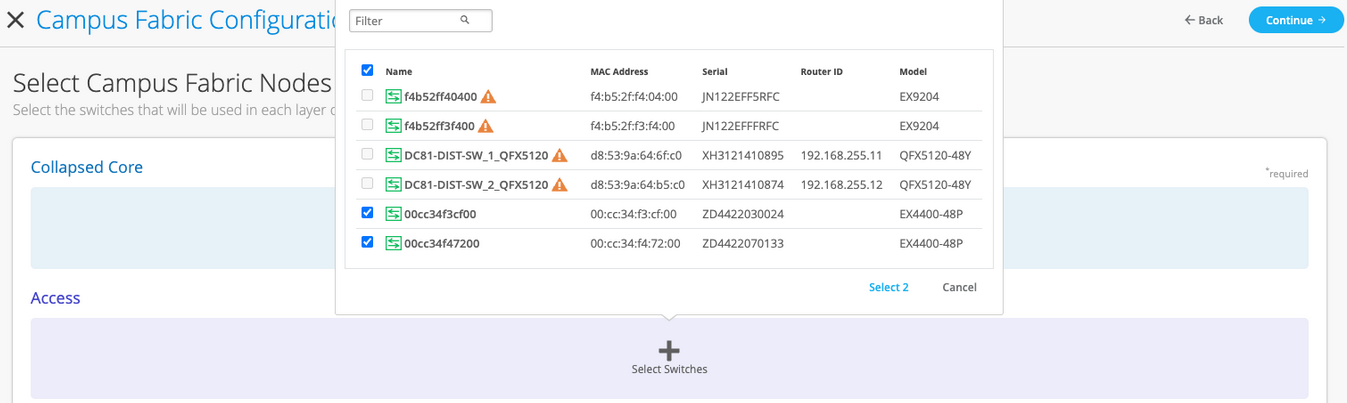
Click Continue to go to the Nodes tab,
where you can select devices that form part of the campus fabric deployment.
-
Add switches to the collapsed core layer and access layer.
We recommend that you validate the presence of each device in the switch inventory before creating the campus fabric.
To add switches:
- Click Select Switches.
- Choose the switches that you want to add to the campus fabric.
- Click Select.
Note:If you leave the Auto Router ID Subnet / Loopback Interface field on the Topology tab blank, you must configure router IDs for the switches manually. To do so, select a switch that you added to the fabric and configure the router ID in the pane that appears on the right. Manual router ID assignment is supported only for IPv4 deployments.
-
After selecting the switches, click Continue to go to the
Network Settings tab, where you can configure the networks.
-
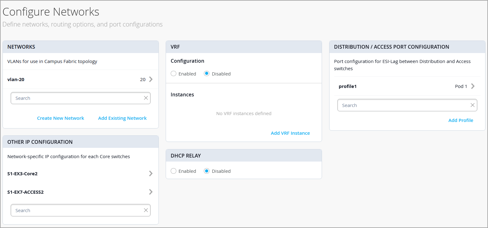
Configure the network settings, as described below:
-
On the NETWORKS tile, add networks or VLANs to the configuration. You can
either create a new network or import the network from the switch template defined on
the Organization > Switch templates page.
To add a new VLAN, click Create New Network and configure the VLANs. The settings include a name, VLAN ID, and a subnet. You can specify IPv4 or IPv6 addresses for the subnet.
To import VLANs from the template:
-
Click Add Existing Network.
-
Select a switch template from the Template drop-down list to view the VLANs available in that template.
-
Select the required VLAN from the displayed list, and click the ✓ mark.
VLANs are mapped to Virtual Network Identifiers (VNIs). You can optionally map VLANs to virtual routing and forwarding (VRF) instances to logically separate the traffic.
-
- Review the settings in the OTHER IP CONFIGURATION tile. This section populates the settings automatically after you specify the networks in the NETWORKS section.
-
Optionally, configure VRF instances.
We recommend
using VRFs when applying Type 5 (IP prefix) policies in a segment-based campus fabric
architecture. By default, Mist places all VLANs in the default VRF.
The VRF option allows you to group common VLANs in the same VRF or separate VRFs
depending on traffic isolation requirements. All VLANs within each VRF have full
connectivity with each other and with other external networking resources. A common
use case is isolation of guest wireless traffic from most enterprise domains except
Internet connectivity. By default, campus fabric provides complete isolation between
VRFs, forcing inter-VRF communications to traverse a firewall. If you require
inter-VRF communication, you need to include extra routes to the VRF. The extra route
could be a default route that instructs the campus fabric to use an external router.
It could also be a firewall for further security inspection or routing
capabilities.
To create a VRF:
-
On the VRF tile, click Add VRF Instance and specify the settings. The settings include a name for the VRF and the networks to be associated with the VRF.
-
To add extra routes, click the Add Extra Routes link on the New VRF Instance page, and specify the route. You can specify IPv4 or IPv6 addresses.
-
- On the CORE / ACCESS PORT CONFIGURATION tile, complete the port configuration for ESI-LAG between the collapsed core and access switches. The settings include a name and other port configuration elements. By default, this configuration includes the networks added on the NETWORKS tile on the same page. If you want to remove or modify the settings, click Show Advanced and configure the settings. Use the tips on the screen to configure the port profile settings.
-
On the DHCP RELAY tile, configure the DHCP relay settings. You have the following
options:
-
Enabled—Configures DHCP relay on all the IRB-enabled devices in campus fabric. This option allows you to enable DHCP Relay on networks that you selected. The network will be populated inside the DHCP Relay tile as long as it is listed on the Networks tab on the same page.
-
Disabled—Disable DHCP relay on the devices in campus fabric. When you select this option, the DHCP relay is disabled on all the IRB-enabled devices. You should carefully select this option as this will remove the locally defined DHCP Relay on the Switch Detail page.
-
None—This option is automatically selected when the campus fabric topology has a mix of devices in terms of the DHCP relay configuration; that is, some devices have the DHCP relay enabled, some have it disabled, and some do not have it defined. This option will be visible for all Campus Fabric topologies that have DHCP Relay locally defined on individual switches.
If you want to remove all locally defined DHCP Relay networks, select Enabled and then choose Remove all existing device level DHCP Networks. You can simplify your DHCP Relay deployment by centralizing any configuration change from the campus fabric workflow.
If you enable DHCP relay in a campus fabric configuration, it is enabled on all the IRB-defined devices in the fabric and disabled on the rest of the devices. For example, in EVPN Multihoming topologies, DHCP relay is enabled on collapsed core devices and disabled on the rest.
-
-
On the NETWORKS tile, add networks or VLANs to the configuration. You can
either create a new network or import the network from the switch template defined on
the Organization > Switch templates page.
- Click Continue to go to the Ports tab, where you can configure the ports and create a connection between the core, distribution, and access layer switches.
-
Configure the switch ports in the collapsed core layer as follows:
- Select a switch in the Collapsed Core section to open the switch port panel.
- From the port panel of the switch, select a port that you want to configure.
-
Specify a port type (for example,
georxe). -
Select:
-
Link to Collapsed Core to connect the port to a core switch.
In the collapsed core layer, you can connect each switch to every other switch to form a full mesh topology. A full mesh topology provides an EVPN Multihoming campus fabric with greater resiliency, which ensures continued network functionality even if one device fails.
-
Link to Access to connect the port to an access switch.
-
- Select the core or access switch (based on the selection in the previous step) on which the link should terminate. You need to configure all the ports that need to be part of the campus fabric.
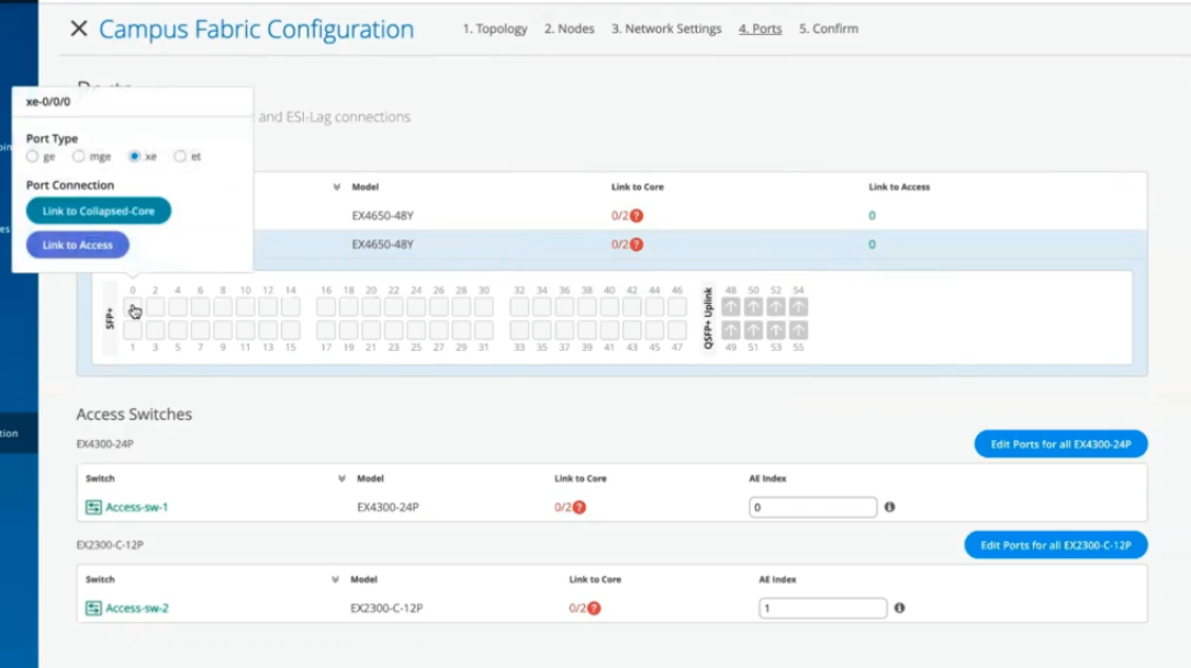 To configure the switch ports in the access layer:
- Select a switch in the Access section to open the switch port panel.
- From the port panel of the switch, select a port that you want to configure.
-
Specify a port type (for example,
georxe).In case the access layer uses a Virtual Chassis (VC), you can configure ports on the Primary and Backup tabs.
For the access switches, select only those interfaces that should be used to interconnect with the distribution switch. The system bundles all interfaces into a single Ethernet bundle through the AE index option. You can specify an AE index value for the access devices.
If you want to view the configuration and status information of a specific port, hover over the numbered box representing that port in the port panel UI.
- Click Continue to go to the Confirmation tab.
- Click each switch icon to view and verify the configuration.
-
After verifying the configuration, click Apply Changes >
Confirm.
This step saves the campus fabric configuration to the Mist cloud and applies it to the switches. If the switches are offline, the configuration will be applied to them when they come online next time. A switch might take up to 10 minutes to complete the configuration.
-
Click Close Campus Fabric Configuration.
After Mist builds the campus fabric, or while it is building the fabric, you can download the connection table. The connection table represents the physical layout of the campus fabric. You can use this table to validate all switch interconnects for the devices participating in the physical campus fabric build. Click Connection Table to download it (.csv format).
-
Verify the campus fabric configuration. To verify, follow the steps listed in the
Verification section in Campus Fabric EVPN Multihoming Workflow.
Hello and welcome to this edition of Wired Assurance. My name is Rohan Chada and today I'll be talking about building an EVPN week stand campus fabric in just four steps. Today we're going to talk about the deployment of EVPN multi homing topology. I'll walk you through the different steps that are required and I can promise you none of those require any CLI configuration.
Everything will be done through the UI and it'll be as simple as you can expect it to be. So let's just jump right into it and talk about EV Pin Multi Hamming. Before we jump into building the EV Pin Multi Hamming topology, let's understand the building blocks of it from a device perspective. Today as you can see, we're going to be using 2 core devices and two access devices.
The EVPN Multi Hamming topology can support up to 4 core devices, a minimum of two and a maximum of four and as many access devices as you'd like. But for this purposes of this video, we'll be using 2 core devices and two access devices. So to begin with, we click on organization and we under the wire tab we see Campus fabric. So as we click on Campus fabric, we can see that we are inside the site EVPN campus primary one and there is no campus fabric configured at this time.
And that's exactly where we'll begin. Click on configure campus fabric and we see that there are three topologies that are presented to us. EVPN multi homing which is collapse code with ESI lag, campus fabric Code distribution which is EVPN code distribution with ESI lag and canvas fabric IP cloth. What you see on the left side of each of these three names is a small diagram that basically depicts the topology that this this entails.
So you basically have above the line that you see the horizontal line in the diagram on each of these topologies. Above the line is where your your evpn vxlan construct exists. And what I mean by that is that's where those devices are, the devices that run Evpn vxlan configuration. Anything below the horizontal line are just pure access devices layer to they can be, they have to be non evpn VXLAN capable devices.
So once you've selected the EVPN multi homing we see that it's a collapsed core and what that means is that two or three layers of EVPN configuration is collapsed into just one layer. So we'll jump right in there by giving it a topology name. We're going to go ahead and call it evpn image. There are two settings that you have to provide on the initial page and that's for the overlay and the underlay settings.
For overlay we use ibgp today and for underlay we use ebgp. The default values will be presented to you, there is no reason to change it if there isn't a purpose behind it. And 65,000 is the local AS and 65,001 is the AS base to begin with for the underlay ebgp. And then we'll increment sequentially on a device spaces starting with 65001.
The loopback prefix as you can see is the the prefix that's used to assign to all the interfaces, all the loopback interfaces on all the devices. These interfaces are used to peer with every other VTAP in the campus fabric. And then last is the subnet, which is again a default value provided that can be changed by the user. This subnet is used to connect the underlying physical interfaces between the campus fabric.
Let's jump right into the next step and click on Continue. At this step we'll be selecting the Campus fabric nodes. In this Campus fabric configuration we'll be selecting 2 Campus course and I'll select Code one and Code 3 for this demo. And as you can see in this nice drop down, you have all the information provided to you and that includes the model as well as the Mac address so you don't have to go back and forth between different pages of the UI.
Every information is provided right here. For the access devices, I'll be picking switch one and switch two. My core devices are EX 465048 wise that are EVPN capable. My access devices are EX 2300 and 4300 that do not understand EVPN.
Hence I am putting these in an access layer. The platform support on a topology basis is on the on the website and we've listed every platform that's supported on a per layer basis. So once you've selected this topology, we know that there are two core devices, 2 access devices. I can click on these core devices and I can see that the basic information about core one I see there is a router ID assigned.
This router ID is assigned as needed for the loop back interface. As I mentioned earlier, that's used for peering between the two core devices. In case of a collapsed core, the two core devices will act as the as the two vtips that basically they will be forming A VXLAN tunnel between each other. The access, which is on the other hand do not necessarily need a router ID, but we've provided them for consistency's sake.
They do not need it, but let's go ahead with that. Step three is basically configuring networks. So networks are basically of Vlans. So we'll go ahead and start creating some new networks here.
I'm going to be assigning some generic names here and I'll call it image vlan 10 and S and vlan ID 10 and I'll give it the subnet 190 to one 6810.0 slash 24 and I'll give it a virtual gateway for 190 to 168 dot 10.1. Now providing this subnet is. This is the only I would say.
This is the second step wherein you'll be providing us a subnet. The IP addressing for the IRB slash SVI interfaces or any IP addressing in the underlying physical interfaces in our fabric is taken care by missed Wire Assurance Campus Fabric. As a user and administrator, you don't have to worry about it. So once you've provided us a subnet, we'll take care of it.
So this virtual gateway will essentially be used for as a common address between the two core devices. So any underlying device, for example an access switch or any any device connected to the access switch will have its gateway as 190 to 168 or 10.1 which will be advertised via avpn and that's why we come in here and manually define it. So as you can see, I created a VLAN, VLAN 10 and voila, we see two IP addresses that have already been chosen to be assigned for the corresponding IRB slash SVI interfaces that will be assigned to code one and code 3 for VLAN 10.
Let's go ahead and create another one and we'll call it image VLAN 20. But in this case I'm not going to assign a subnet or virtual git net because I want to route for this particular VLAN. I want to route on the the the firewall of the campus fabric. So my the two core devices that I have will be connected dual home to a firewall and I want the routing to happen for this particular VLAN on the firewall.
So I'm going to skip this and this is basically a bridged overlay design wherein we'll assign the VNI to the corresponding VLAN 20, but we will not be configuring A subnet or a gateway on the 2 core devices. This is one way of creating a VLAN. The other way of adding a VLAN to the campus fabric is if you have existing network on the sites already. So we'll click on existing network and what we see is that there is a common VLAN that we already created earlier before we started this demo on an entire site.
So using the site configuration here, I created a VLAN called site wide VLAN with a VLAN ID of 100 and that's it. And what that did was all the devices in that site inherited the site wide VLAN. So I'm going to take site wide VLAN and I'm going to add that. So now I'm told that there is a virtual gateway that is required.
OK, there is a virtual gateway required. So we'll go ahead and add the virtual gateway. The subnet basically was inherited from the the site configuration where I had created VLAN printer. So I'm being told that the provided gateway is already used.
OK, so here we have 3 Vlans and as we already see that for two of them the static IP addresses have already been defined. For VLAN 10 there are two IP addresses, code one and code 3. Similarly for site VLAN 100, we have two IP addresses, one each for core one and core 3. And as we already know VLAN 20 is a doesn't have a virtual gateway on the collapse core, so we do not have a gateway for that.
Now let's jump into VRF and understand this is virtual routing and forwarding wherein you can create separate routing instances. You can basically increase the security in your network by segregating the Vlans in different routing instances. A different routing instance basically means that there is a different routing table on a per VLAN basis or however many Vlans you would like in that particular VRF. So we'll go and assign this name vrf one and then we'll we'll add image vlan 10 to vrf one if if there is a need.
I can always add extra routes within the VRF as well and that is an option. You go ahead and another VRF called VRF 2 and I'll use site by vlan for this particular VRF 2. The last step on this page is to basically configure the core access port configuration. This is the port configuration towards the access switches from the collapse code as it if you read the description it says this is the ESL configuration.
So let's just assign it a name and let's call it Yesi LAG, any name of the book, but Yesi Haffen LAG is what I've assigned. We presume that all the Vlans and networks that you've defined here are going to be a part of the ESI LAG configuration, and so we automatically add them to the trunk networks. You can come in here and manually change any settings that you would like. If you would like a smaller MTU or if you would like to manipulate the MTU size here to your environment needs, you can do that.
You can enable storm control. You can also enable Poe if that's a requirement, change the speed, duplex, add native VLAN. All of that is an option that we've provided. This is the last and final step and what we see here is there are different port panels.
These port panels are on a platform basis. For the purposes of this video, we are using EX4650 and two other platforms. So we'll show you the appropriate port panels as needed whenever any platform other than these are used. So let's jump right into it and let's let I'll go ahead and I'll configure these interfaces quickly.
So what I've done at this point is I've connected all the two collapsed core devices with the other two access devices. Basically the requirement is that there should be two interfaces connected to each other between the two core devices. Evpn multi Homing has that requirement for redundancy and then core one needs to connect to both access switch one and Access switch 2. Similarly code 3 needs to connect to both access switch one and access Switch 2.
So once those interfaces have been have been connected here you've told the missed UI that these are the interfaces. We can proceed and we can click on continue. This is the last step wherein you confirm that the topology changes that you want are there and if you click on code 1, we can see that on the right. We see a lot of information about everything that we've done so far.
We see the model, we see the router ID, we see the Vlans that we wanted in the campus fabric. Along with the Vlans we also see the IP addresses. I see that there are two IP addresses and three Vlans. One of them is and doesn't have an IP address and that is basically a bridge overlay design as I mentioned earlier.
We also see the connections by the way. I can see and I can verify here the connections connections to collapsed core or three and access switch one and access switch two at any point in this entire step. If you'd like to access the remote shell, we've provided you that option as well. So before you hit apply changes, if you'd like to log into your device you can do that here.
You can click on remote shell and pop up window will open for you and at this point you can you can look at your configuration. You can look at how your devices are connected. I see here that my devices are connected or one connects to two core 3 interfaces and core one has a connection to switch to and switch one as well. So a a little handy tool here where you can verify by logging into the device.
Let's click apply changes and confirm. At this time, what has happened is that the configuration that we decided to push to the devices is being pushed and is being committed to the junuper devices and right after that's committed, BGP Underlay as well as Overlay will be provisioned. Once BGP Underlay is provisioned, overlay and the VX LAN tunnels will come up, the VX LAN tunnel will be two way between collapsed Core one and collapsed Core 2. Let's just jump right into the switches while this configuration is happening.
We look at what's the scenario and the switches and the configuration that we pushed under the hood. Remember, everything that we did so far was based on UI. We did not touch the CLI. We did not make any CLI changes manually.
You did not have to define the EVPN configuration or the BGP configuration or the underlying physical connectivity. This is the value of Missed Wire Assurance Campus Fabric. Let's click on Utilities and click on Download JS Config. We see that configuration file has been downloaded.
This is a. This is a handy tool. What this does is it enables us to verify the configuration. All of us have been used to configuring things while the CLI and so it is very important that we verify that if you're doing this for the first time that everything that you want in the configuration should be there.
You could be a Greenfield environment or or a brownfield environment. You should be able to verify your configuration. So let's dive right into it. Let's look at this.
So as we can see, the first thing I see is I see some BGP configuration here. That's very important. We see the underlay BGP configuration here between the two core devices. There are two peers here on 2 interfaces.
We see the overlay configuration here since there's only one peer for core one and that is core three. There is only one neighbor. We see some EVPN configuration here, right? We also see the ESI LAG configuration here that was pushed by Campus Fabric.
None of that required us to push anything through CLI. We see 22 LAG interfaces AE0 and AE1AE0. It's towards switch one and AE three is towards switch two. We see the IRB configuration as we discussed earlier.
IRB 10 is the the first VLAN that we defined with a gateway and IRB 100 is the third one that was inherited from the site wide template. We also see the VRF configuration here. So as we can see, there's VRF one configuration that has one VLAN IRB .10. We also have type 5 routes as a part of it.
We also see VRF 2 configuration in this VRF 2 configuration, what we see is IRP 100. The second, I'm sorry, the third VLAN that we chose is also there. And then if you look at the configuration here, we see all three Vlans, even the VLAN, even the VLAN that we made bridged overlay is a part of the configuration has a VNI. So we can go ahead and we can assign the gateway for this particular VLAN on either the router of the campus fabric or the firewall based on your environment.
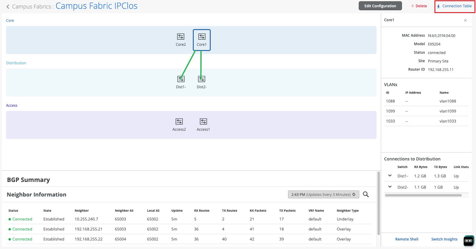
So now that we've looked at the configuration, let's look at how our EVPN campus fabric is doing and what do the EVPN insights tell us. So the EVPN insights, it's basically a pretty layer on top of the campus fabric that tells you about a few green and red links. And those green and red links are not not just the the interface status. They tell you some good information about your peering in the network.
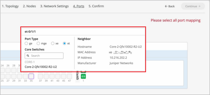
So we looked at there are a few green links. We see that the status is up, but we see these triangles. And these triangles are not, they do not look great. So when I hover over this topology, I am being told that the selected port is not connected to the correct switchboard in the campus traffic topology.
What that basically means is that the the the back end of the campus fabric knows that the core one to core 3 port that I've selected is not the right port and instead it is something else. It is smart enough to understand that there was another port that should have been connected, but I have connected the wrong the wrong port and that is absolutely right. So I'm going to jump right into the campus fabric and change that quickly for you guys. So I'll click on edit configuration and go right to the last step and I'll change this zero to 1 and we'll hit continue and we'll apply changes and save them while the provisioning takes a while.
I'll be right back in a minute. So, so we're back. So as we can see our pretty green lines are back. What and what that means is that we've you corrected the interface that was not correct in the right way.
Campus Fabric was smart enough to let us know that the interfaces that were connected between code one and code three were not right. As you can see, I had 000 earlier and I switched that over to 001 and after doing that my BGP neighborship came back. And then here we can see if I click on any device the statistics between the two devices. We can also see, as I mentioned earlier, the Vlans and the IP addresses.
Thank you. This concludes our campus fabric demo today. I'll summarize all the things that we did today in this last 2025 minute session. So we built a campus fabric using the Mist UI.
None of those steps included anything to do on the CLI. We built a campus fabric in four steps wherein we as a step one, we selected the kind of topology that the user would want. As a second step, we chose the campus fabric nodes that will participate in the campus fabric. The third step was to provide us the networks that will be participating in the in the campus fabric.
And the last and final step was the connectivity of the devices itself. It's as simple as that.