LAN Interfaces
Use this information to enter the settings in the LAN section of a WAN Edge template, hub profile, or device configuration.
Navigating to a LAN Configuration
You'll find LANs on the configuration page for your WAN Edge templates (for spokes), hub profiles, and individually managed devices.
-
For a WAN Edge template—From the left menu, select Organization > WAN > WAN Edge Templates. Click a template, or create one. Scroll down to the LAN section.
-
For a hub profile—From the left menu, select Organization > WAN > Hub Profiles. Click a profile, or create a new one. Scroll down to the LAN section.
-
For an individually managed WAN Edge device—From the left menu, select WAN Edges > WAN Edges. Click a device. Scroll down to the LAN section.
LAN Settings Overview
Associate your LAN with the appropriate port on the device, and add network services as needed.
The LAN section of the configuration includes these sub-sections:
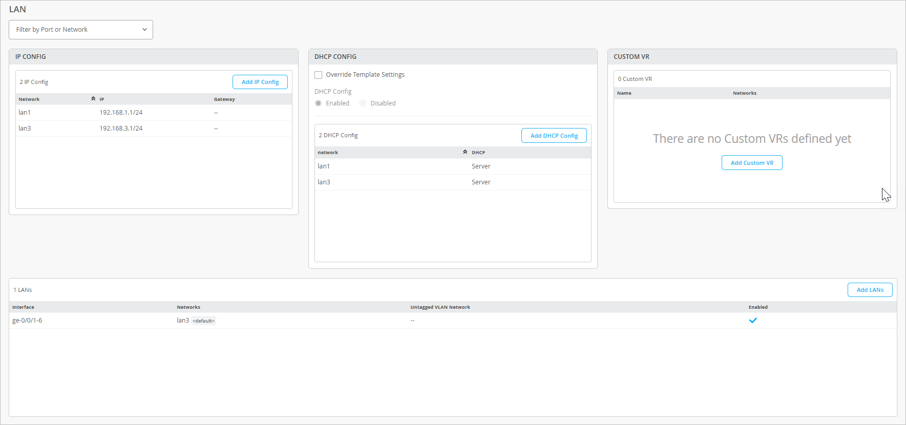
IP Config
In the IP Config section, you see the networks, IP addresses, and redirect gateways (applicable to Session Smart Routers only) for the LANs that you've defined. To add a LAN, click Add IP Config, enter the settings in the side panel, and then click Add at the bottom of the panel.
| Field | Description |
|---|---|
| Network | Select an available network from the drop-down menu. This list includes all networks that you previously added on the Networks page. For help, see Network Settings. |
| IP Address | Enter the IPv4 address for this interface. |
| Prefix Length | Enter the prefix length for the interface. |
|
Redirect Gateway (SSR Only) |
(For Session Smart Routers only) Enter the IP address of redirect gateway . |
DHCP Config
In the DHCP Config section, you can enable or disable DHCP and see the DHCP configs that you've defined. To add a DHCP config, click Add DHCP Config, enter the settings in the side panel, and then click Add at the bottom of the panel.
| Field | Description |
|---|---|
| Network | Select an available network from the drop-down menu. This list includes all networks that you previously added on the Networks page. For help, see Network Settings. |
| DHCP Type | Select DHCP Server or DHCP Relay. Then complete the asterisked fields. |
| DHCP Relay Settings | |
| Servers | Enter a comma-separated list of IP addresses for the relay servers. |
| DHCP Server Settings | |
| IP Start, IP End | Use these two fields to specify the range of IP addresses to use. |
| Gateway | Enter the IP address of the network gateway. |
| Maximum Lease Time | Specify the maximum duration of a DHCP lease, from 3600 seconds (1 hour) to 604800 seconds (1 week). |
| DNS Servers | Enter IP address of the Domain Name System (DNS) server. |
| Server Options |
The Server Options table displays the server options that you've already defined. Click an existing option to edit, or click Add Option. The settings include:
After completing the fields, click the check mark in the Add Server Option title bar. |
| Static Reservations |
This section lists the addresses in the DHCP range that are reserved for devices that require static IP addresses. Click an existing reservation to edit, or click Add Reservation. The settings include:
After completing the fields, click the check mark in the Add Static Reservation title bar. |
Custom VR
If you've set up Virtual Routing and Forwarding (VRF) instances for your WAN, you also can configure VRF Route Leaking (propagation) to share route information across these instances. It provides route isolation and segmentation from other routes. A common implementation of this feature is to isolate guest, PCI, or IoT network. Put each network in a separate VRF instance.
| Field | Description |
|---|---|
| Name | Enter a descriptive name to identify this virtual router. |
| Network | Select an available network from the drop-down menu. This list includes all networks that you previously added on the Networks page. For help, see Network Settings. |
| Extra Routes |
This section lists the extra routes that you've defined for this VR. Click an existing route to edit, or click Add Extra Routes. The settings include:
|
LAN Configurations
The LAN section lists the LANs that you've defined. To add a LAN, click Add LANs, enter the settings in the side panel, and then click Add at the bottom of the panel.
| Field | Description |
|---|---|
| Interface |
Enter the interface, multiple interfaces separated by commas, or a range of interfaces. The number of interfaces depends on the device. For example, if the device only supports four interfaces, you can add up to four in the LACP bundle. Examples:
Then select additional interface options as needed:
|
| Description |
Enter a description to identify this interface. |
| Network |
Select a network from the list. When you do, the remaining configuration is filled in automatically. The Network list includes all networks that you previously added on the Networks page. For help, see Network Settings. |
|
Untagged VLAN Network (SRX Only) |
If this interface is for an SRX, select the network to use for untagged VLAN traffic. |