The J-Web Setup Wizard
Configure SRX Series Firewalls Using the J-Web Setup Wizard
Using the Setup wizard, you can perform step-by-step configuration of a services gateway that can securely pass traffic.
For information on how to start and access the J-Web user interface, see Access the J-Web User Interface.
You can choose one of the following setup modes to configure the services gateway:
-
Standalone mode—Configure your SRX Series Firewall to operate in a standalone mode. In this mode, you can configure basic settings such as device credentials, time, management interface, zones and interfaces, and DNS servers and default gateways.
-
Cluster (HA) mode—Configure your SRX Series Firewall to operate in a cluster (HA) mode. In the cluster mode, a pair of devices are connected together and configured to operate like a single node, providing device, interface, and service level redundancy.
Note:You cannot configure Standalone or Passive mode when your device is in the HA mode.
-
Passive (Tap) mode—Configure your SRX Series Firewall to operate in a TAP mode. TAP mode allows you to passively monitor traffic flows across a network. If IPS is enabled, then the TAP mode inspects the incoming and outgoing traffic to detect the number of threats.
Note:SRX5000 line of devices, SRX4600, and vSRX Virtual Firewall devices do not support the passive mode configuration.
To help guide you through the process, the wizard:
-
Determines which configuration tasks to present to you based on your selections.
-
Flags any missing required configuration when you attempt to leave a page.
To configure SRX Series Firewalls using the J-Web Setup wizard:
-
Select the configuration mode that you want to setup and click Start.
The Setup Wizard page appears.
-
For standalone and passive (Tap) modes, complete the configuration according to the guidelines provided in Table 2.
If you select Cluster (HA) Mode, for the configuration information see Configure Cluster (HA) Setup.
Note:The root password is mandatory in the setup wizard. All other options are optional. In the passive mode, configuration of the management interface, Tap interface, and services are mandatory.
-
Review the configuration details. If you want to change the configuration, click Edit Configuration, else click Finish.
Wait till the configuration is committed. A successful message is displayed once the entire configuration is committed to the device.
Note:-
If the commit fails, J-Web displays you the error message received from CLI and you remain on the wizard’s last page. Check over your configuration and make changes as necessary so that the commit succeeds.
-
For SRX300 line of devices and SRX550M devices in passive mode, an additional message is displayed about the device reboot if you have enabled Juniper ATP Cloud or Security Intelligence services. For other SRX Series Firewalls, the device will not reboot.
-
-
Read if any instructions are available and then click Open J-Web Login Page.
The J-Web Login page appears.
-
Enter the root username and password and click Log In.
Launch Pad screen appears until the J-Web UI is loaded. See J-Web: A First Look.
Example: J-Web Wizard for Standalone Mode
In this section, we'll show you a typical J-Web setup wizard workflow for standalone mode operation. The J-Web interface is updated and modified over time. The below example is representative of the typical workflow. This specific example is based on the Junos 21.3R1 release.
Table 1 provide details on the configuration parameters used for initial setup.
| Configuration Parameter | Example Value |
|---|---|
| Root Password | "Sample_psswd_for_doc-only!" |
| Hostname | SRX-300 |
| Management interface | ge-0/0/1 |
| Management IP and CIDR | 10.102.70.79/24 |
| Access Protocols | HTTPS, SSH, Ping |
| Static route for management | 10.0.0.0/8, next hop 10.102.70.254 |
| NTP and DNS |
|
| Remote access | SSH with root login allowed |
| Non root user (Admin/super user account) | user "lab", password "Sample_psswd_for_doc-only!" |
| Security Policy | Default |
Refer to Access the J-Web User Interface for information on how to access the J-Web interface. This example is based on an SRX300. Based on the information in Table 1, the management device is set for DHCP is and is attached to the ge-0/0/1 interface. When running a factory default configuration, the ge-0/0/1 interface is configured as a DCHP server and assigns an address to the PC from the 192.168.1.0/24 subnet. To access J-Web in this scenario, you point the browser to https://192.168.1.1.
-
We begin at the J-Web setup wizard screen. You click on the option for Standalone Mode and then on the Start button.
Figure 1: J-Web Setup Wizard Modes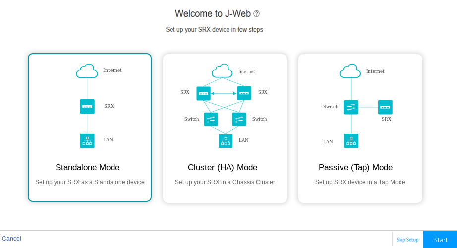
-
Configure the device name, root user, and non-root (administrator) user login information on the Device Credentials page.
Note:Enable SSH for root user.
Figure 2: J-Web Setup Wizard Device Credentials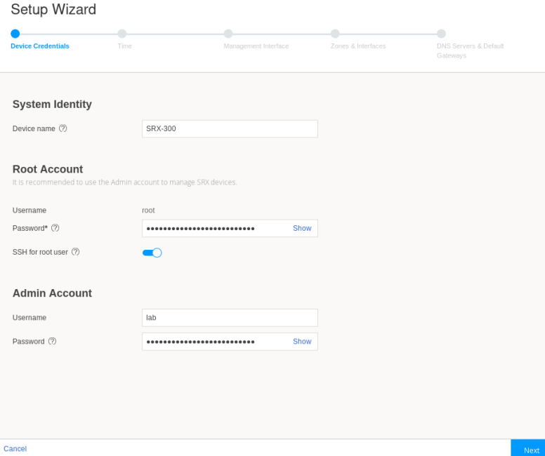
-
Click Next.
The Time page opens.
-
Configure the timezone, time source, and in the case of NTP, the desired server(s).
Figure 3: J-Web Setup Wizard Time Servers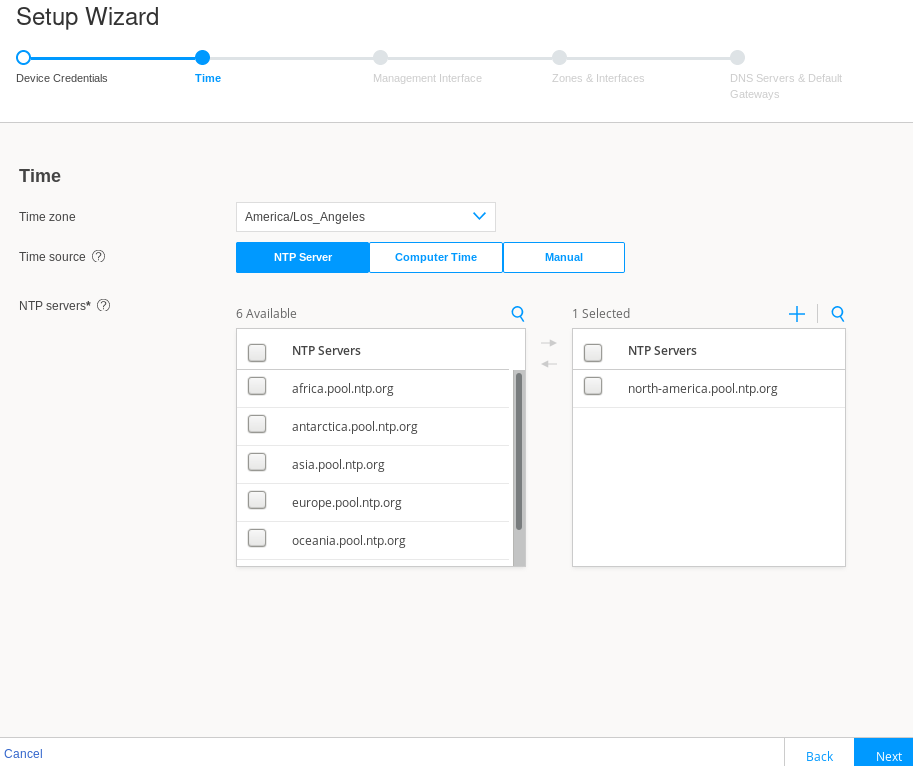
-
Click Next.
The Management Interface page opens.
-
Again, this setup example is based on a SRX 300 series device. This SRX Series Firewall does not have a dedicated management interface. In many cases, their role in branch offices results in their being managed remotely through the WAN interface (ge-0/0/0). On larger SRX Series Firewalls, a dedicated management interface (fxp0) is provided for attachment to an out-of-band (OOB) management network. In this example, you configure the ge-0/0/1 interface as a dedicated OOB management interface.
Figure 4: J-Web Setup Wizard Management Interface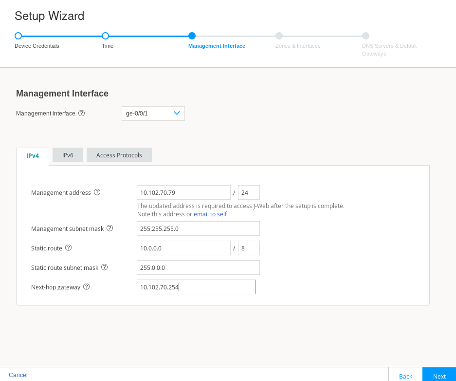
Before continuing, you click on the Access Protocols tab to confirm that HTTPS, SSH, and Ping (ICMP echo) are permitted on the management interface.
Figure 5: J-Web Setup Wizard Access Protocols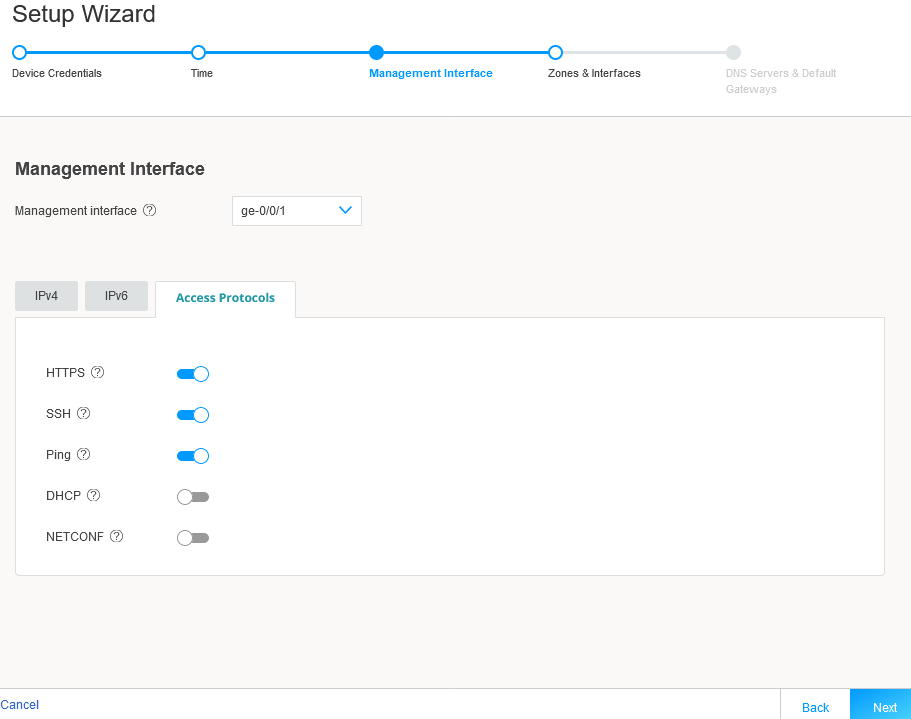
-
Click Next.
The Zones & Interfaces page opens.
-
In this example you maintain the factory default security policy. Recall, you can always use J-Web to later modify all aspects of the configuration, to include security, after you complete the initial setup.
Figure 6: J-Web Setup Wizard Security Zones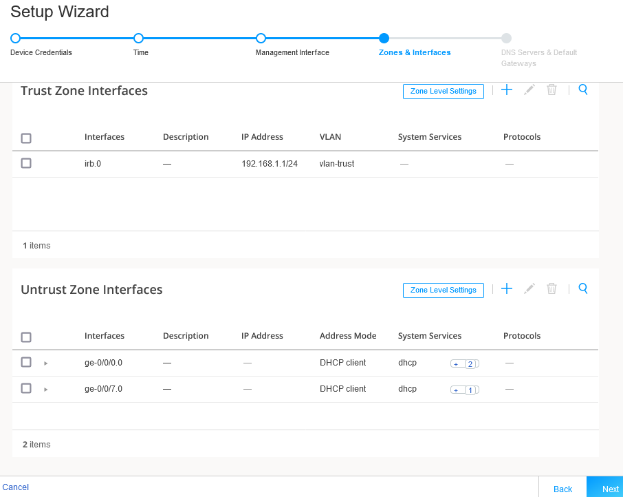
-
Click Next.
The DNS Servers & Default Gateways page opens.
-
Configure a public DNS server IP and leave the default gateway fields blank. If desired, you can add default routes to access other networks that should be reachable over the management interface.
Figure 7: J-Web Setup Wizard DNS and Default Gateways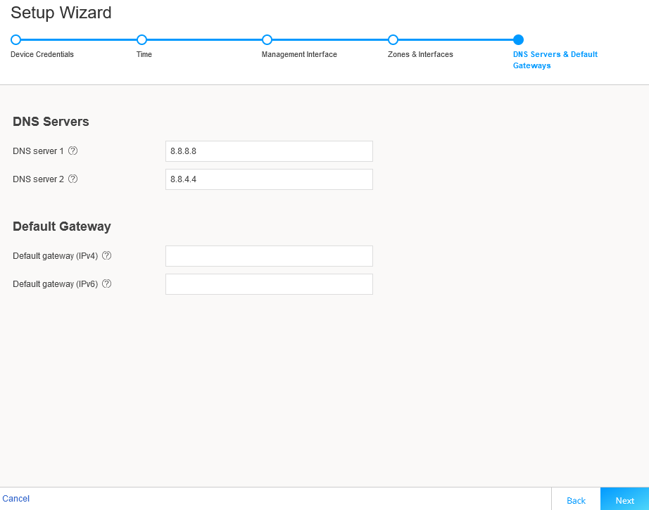
-
Click Next.
The Setup Wizard opens. This page summarizes your configuration. If desired, you use the Edit Configuration option to make changes.
Figure 8: J-Web Setup Wizard Summary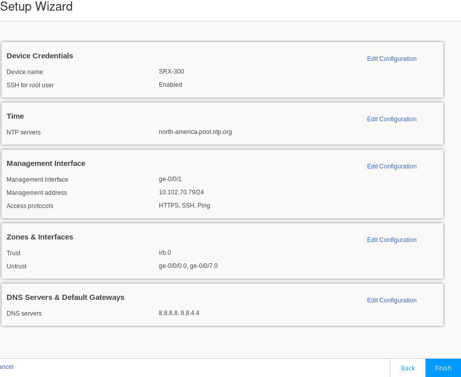
-
When satisfied with the configuration, click on Finish. The Setup Wizard displays a status page to indicate the initial configuration is being pushed to the SRX Series Firewall.
Figure 9: J-Web Setup Wizard Configuration Push
In a few moments, the Setup Successful page is displayed. Congratulations! Your SRX Series Firewall is remotely accessible and is ready for ongoing management using the J-Web interface.
Figure 10: J-Web Setup Wizard Successful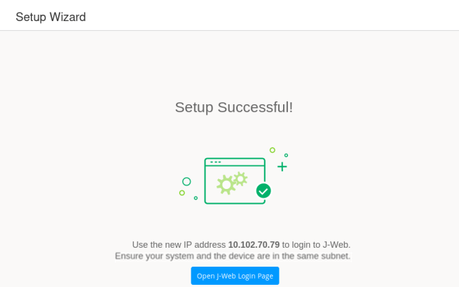 Note:
Note:Recall that in this SRX-300 based example the management device is directly connected to the SRX on the ge-0/0/1 port. You performed initial configuration using a 192.168.1.0/24 address that was assigned by the SRX Series Firewall using DHCP.
Using the setup wizard, you configured the ge-0/0/1 interface as a dedicated management interface and assigned a static IP address of 10.102.70.89/24. As a result, the ge-0/0/1 interface no longer functions as a DHCP server.
Once the new configuration is activated, you must ensure the management device is configured with a compatible IP address if it remains directly connected to the ge-0/0/1 interface. You log in back into J-Web using https://10.102.70.89.
Congratulations! You have completed initial setup using J-Web. Keep going by visiting the below links:
- Get a quick overview of the J-Web user interface: Explore J-Web
- Access the device dashboard: Dashboard Overview
- Monitor device traffic: Monitor Traffic Map
- Configure your device: Configure Basic Settings
- Use the Getting Started panel: Security J-Web Getting Started
J-Web Setup Wizard Parameters
This section serves as a reference for the mode specific parameters that you can configure using the J-Web Setup Wizard. Table 2 provide details of the parameters that can be configured in the standalone and passive (Tap) modes. For details on parameters supported in cluster (HA) mode, see Configure Cluster (HA) Setup.
|
Field |
Action |
|---|---|
| Device Credentials | |
| System Identity | |
|
Device name |
Enter a hostname. You can use alphanumeric characters, special characters such as the underscore (_), the hyphen (-), or the period (.); the maximum length is 255 characters. |
| Root Account | |
|
Username |
Displays the root user. Note:
We recommend that you do not use root user account as a best practice to manage your devices. |
|
Password |
Enter a password. You can use alphanumeric characters and special characters; the minimum length is six characters. |
|
SSH for root user |
Enable this option to allow the root login (to the device) using SSH. |
| Admin Account | |
|
Username |
Enter the admin username to manage the device. |
|
Password |
Enter the admin password. |
| Time Configuration | |
| Time | |
|
Time zone |
Select a time zone from the list. |
|
Time source |
Select either NTP server, computer time, or Manual to configure the system time:
|
| Management Interface Configuration | |
|
Management
Interface
Note:
If you change the management IP address and click Next, a warning message appears on the Management Interface page that you need to use the new management IP address to log in to J-Web because you may lose the connectivity to J-Web. |
|
|
Management interface |
Select an interface from the list. If fxp0 port is your device’s management port, then the fxp0 port is displayed. You can change it as required or you can select None and proceed to the next page. Note:
|
|
IPv4
Note:
Click email to self to get the newly configured IPv4 or IPv6 address to your inbox. This is useful if you lose connectivity when you change the management IP address to another network. |
|
|
Management address |
Enter a valid IPv4 address for the management interface. Note:
If fxp0 port is your device’s management port, then the fxp0 port’s default IP address is displayed. You can change it if required. |
|
Management subnet mask |
Enter a subnet mask for the IPv4 address. If you have changed the management address, use the new IP address to access J-Web. |
|
Static route |
Enter an IPv4 address for the static route to route to the other network devices. |
|
Static route subnet mask |
Enter a subnet mask for the static route IPv4 address. |
|
Next hop gateway |
Enter a valid IPv4 address for the next hop. |
| IPv6 | |
|
Management access |
Enter a valid IPv6 address for the management interface. |
|
Management subnet prefix |
Enter a subnet prefix length for the IPv6 address. |
|
Static route |
Enter an IPv6 address for the static route if required to reach the device through the management interface. |
|
Static route subnet prefix |
Enter a subnet prefix length for the static route IPv6 address. |
|
Next hop gateway |
Enter a valid IPv6 address for the next hop. |
|
Access
Protocols
Note:
This option is available for all the ports except fxp0. |
|
|
HTTPS |
This option is enabled by default. |
|
SSH |
This option is enabled by default. |
|
Ping |
Enable this option for ping service. |
|
DHCP |
Enable this option for DHCP service. |
|
NETCONF |
Enable this option for NETCONF service. |
| Zones & Interfaces | |
|
Security
Policy
Note:
This option is available only for the Standalone mode. For the Passive (Tap) mode, this option is available under Tap Settings. |
|
|
From Zone |
Name of the source zone. In the standalone mode, permits all traffic from the trust zone. |
|
To Zone |
Name of the destination zone. In standalone mode, permits all traffic from the trust zone to the untrust zone. |
|
Source |
Name of the source address (not the IP address) of a policy. |
|
Destination |
Name of the destination address. |
|
Application |
Name of a preconfigured or custom application of the policy match. |
|
Action |
Action taken when a match occurs as specified in the policy. |
|
Zones
—Displays the available trust and untrust zones configuration. |
|
|
Trust Zone
Interfaces
Note:
This option is available only for the Standalone mode. |
|
|
Add Trust Zone Interface |
Click + to add trust zone interface. For more information on the fields, see Table 3. |
|
Edit Trust Zone Interface |
Select an interface and click the pencil icon at the right corner of the table to modify the configuration. |
|
Delete Trust Zone Interface |
Select an interface and click the delete icon at the upper-right corner of the table. A confirmation window appears. Click Yes to delete the selected interface or click No to discard. |
|
Search Trust Zone Interface |
Click the search icon at the right corner of the table to quickly locate a zone or an interface. |
|
Detailed View Trust Zone Interface |
Hover over the interface name and click the Detailed View icon to view the zone and interface details. |
| Trust Zone Interfaces—Zone Level Settings | |
|
Zone name |
View the trust zone name populated from your device factory default settings. Note:
For standalone mode, trust and untrust zones are created by default even if these zones are not available in the factory default settings. |
|
Description |
Enter the description for trust zone. |
|
System services |
Enable this option for the types of traffic that can reach the device on a particular interface. By default, this option is enabled. You can disable if required. |
|
Protocols |
Enable this option to configure the device to perform stateful network traffic filtering on network packets using network traffic protocols (for example, TCP and UDP). By default, this option is enabled. You can disable if required. |
|
Application tracking |
Enable this option to collect byte, packet, and duration statistics for application flows in the specified zone. |
|
Source identity log |
Enable this option for the device to log the user identity information based on the source zone configured in the security policy. |
| Untrust Zone Interfaces | |
|
Add Untrust Zone Interface |
Click + to add untrust zone interface. For more information on the fields, see Table 4. |
|
Edit Untrust Zone Interface |
Select an interface and click the pencil icon at the right corner of the table to modify the configuration. |
|
Delete Untrust Zone Interface |
Select an interface and click the delete icon at the upper-right corner of the table. A confirmation window appears. Click Yes to delete the selected interface or click No to discard. |
|
Search Untrust Zone Interface |
Click the search icon at the upper-right corner of the table to quickly locate a zone or an interface. |
|
Detailed View Untrust Zone Interface |
Hover over the interface name and click the Detailed View icon to view the zone and interface details. |
| Untrust Zone Interfaces—Zone Level Settings | |
|
Zone name |
View the untrust zone name populated from your device factory default settings. Note:
For standalone mode, trust and untrust zones are created by default even if these zones are not available in the factory default settings. |
|
Description |
Enter the description for untrust zone. |
|
Application tracking |
Enable this option to collect byte, packet, and duration statistics for application flows in the specified zone. |
|
Source identity log |
Enable this option for the device to log the user identity information based on the source zone configured in the security policy. |
| DNS Servers & Default Gateways | |
| DNS Servers | |
|
DNS server 1 |
Enter the IPv4 or IPv6 address of the primary DNS. |
|
DNS server 2 |
Enter the IPv4 or IPv6 address of the secondary DNS. |
| Default Gateway | |
|
Default gateway (IPv4) |
Enter the IPv4 address of the next possible destination for any network. |
|
Default gateway (IPv6) |
Enter the IPv6 address of the next possible destination for any network. |
|
Tap
Settings
Note:
This option is available only for the Passive (Tap) mode. |
|
| Tap Settings | |
|
Tap interface |
Select the interface from the list. |
|
IP-IP tunnel inspection |
Enable this option for the SRX Series Firewall to inspect pass through traffic over an IP-IP tunnel. |
|
GRE tunnel inspection |
Enable this option for the SRX Series Firewall to inspect pass through traffic over a GRE tunnel. |
|
Security
Policy & Advanced Services
Note:
Your device must have internet connectivity to use IPS, Web filtering, Juniper ATP Cloud, and Security threat intelligence services. |
|
|
From Zone |
Name of the source zone. In the Tap mode, permits all traffic from the tap zone. |
|
To Zone |
Name of the destination zone. In the Tap mode, permits all traffic from the TAP zone to the TAP zone. |
|
Source |
Name of the source address (not the IP address) of a policy. |
|
Destination |
Name of the destination address. |
|
Application |
Name of a preconfigured or custom application of the policy match. |
|
Action |
Action taken when a match occurs as specified in the policy. |
| Content Security | |
|
Content Security |
Enable this option for configuring Content Security services. |
|
License |
Enter Content Security license key and click Install License to add a new license. Note:
|
|
Content Security type |
Select an option to configure Content Security features:
|
|
Web filtering type |
Select an option:
|
| IPS | |
|
IPS |
Enable this option to install the IPS signatures. |
|
License |
Enter the license key and click Install License to add a new license. Note:
The installation process may take few minutes. |
|
IPS signature |
Click Browse to navigate to the IPS signature package folder and select it. Click Install to install the selected IPS signature package. Note:
You can download the IPS signature offline package at https://support.juniper.net/support/downloads/. |
| ATP Cloud | |
|
ATP Cloud |
Enable this option to use Juniper ATP Cloud services. Note:
After the Juniper ATP Cloud configuration is pushed, only the SRX300 line of devices and SRX550M devices are rebooted. Your device must have internet connectivity to enable Juniper ATP Cloud enrollment process through J-Web. |
| Security Intelligence | |
|
Security intelligence |
Enable this option to use Security intelligence services. Note:
After the Security Intelligence configuration is pushed, only the SRX300 line of devices and SRX550M devices are rebooted. Your device must have internet connectivity to enable Juniper ATP Cloud enrollment process through J-Web. |
| User Firewall | |
|
User Firewall |
Enable this option to use user firewall services. |
|
Domain name |
Enter a domain name for Active Directory. |
|
Domain controller |
Enter domain controller IP address. |
|
Username |
Enter a username for administrator privilege. |
|
Password |
Enter a password for administrator privilege. |
|
Field |
Action |
|---|---|
| General | |
|
Type (family) |
|
|
Interfaces |
Select an interface from the Available column and move it to the Selected column. Note:
This option is available only for the Switching family type. |
|
VLAN
Note:
This option is available only for the Switching family type. |
|
|
Name |
Enter a unique name for the VLAN. |
|
VLAN ID |
Enter the VLAN ID. |
| IPv4 | |
|
IPv4 address |
Enter a valid IPv4 address for the switching or the routing interface. |
|
Subnet mask |
Enter a subnet mask for the IPv4 address. |
| IPv6 | |
|
IPv6 address |
Enter a valid IPv6 address for the switching or the routing interface. |
|
Subnet prefix |
Enter a subnet prefix for the IPv6 address. |
| DHCP Local Server | |
|
DHCP local server |
Enable this option to configure the switch to function as an extended DHCP local server. |
|
Pool name |
Enter the DHCP pool name. |
|
Pool start address |
Enter the starting IPv4 address of the DHCP server pool address range. This address must be within the IPv4 network. |
|
Pool end address |
Enter the ending IPv4 address of the DHCP server pool address range. This address must be within the IPv4 network. Note:
This address must be greater than the address specified in Pool start address. |
|
Propagate settings from |
Select an option from the list. Propagation of TCP/IP settings (such as, DNS and gateway address) received on the device interface acting as DHCP client. |
| Services & Protocols | |
|
System Services |
Select system services from the list in the Available column and then click the right arrow to move it to the Selected column. The available options are:
|
|
Protocols |
Select protocols from the list in the Available column and then click the right arrow to move it to the Selected column. The available options are:
|
|
Field |
Action |
|---|---|
| General | |
|
Interface |
Select an interface from the list. |
|
Interface unit |
Enter the interface unit value. |
|
VLAN ID |
Enter the VLAN ID. Note:
VLAN ID is mandatory if the interface unit is higher than zero. |
|
Description |
Enter the description for the interface. |
|
Address Mode |
Select an address mode for the interface. The available options are DHCP Client, PPPoE (PAP), PPPoE (CHAP) and Static IP. Note:
PPPoE (PAP) and PPPoE (CHAP) are not supported for SRX5000 line of devices and if any of the devices are in passive mode. |
|
Username |
Enter a username for PPPoE (PAP) or PPPoE (CHAP) authentication. |
|
Password |
Enter a password for PPPoE (PAP) or PPPoE (CHAP) authentication. |
|
IPv4
Note:
This option is available only for the Static IP address mode. |
|
|
IPv4 Address |
Enter a valid IPv4 address for the interface. |
|
Subnet Mask |
Enter a subnet mask for the IPv4 address. |
|
IPv6
Note:
This option is available only for the Static IP address mode. |
|
|
IPv6 Address |
Enter a valid IPv6 address for the interface. |
|
Subnet Prefix |
Enter a subnet prefix for the IPv6 address. |
| Services & Protocols | |
|
System Services |
Select system services from the list in the Available column and then click the right arrow to move it to the Selected column. |
|
Protocols |
Select protocols from the list in the Available column and then click the right arrow to move it to the Selected column. |