Help us improve your experience.

Let us know what you think.

Do you have time for a two-minute survey?


Connecting and Configuring an EX Series Switch (J-Web Procedure)

There are two ways to connect and configure an EX Series switch: one method is through the console by using the CLI and the other is by using the J-Web interface.

Starting in Junos OS Release 19.2R1, J-Web supports EX4650 switches.

Note:

You cannot connect to and perform initial configuration of EX2200-24T-4G-DC, EX4300-48MP, EX4300-48MP-S switches, and EX4600 switches using EZSetup procedure from the J-Web interface. For EX2200-24T-4G-DC switches, you must use EZSetup from the switch console. For EX4300-48MP, EX4300-48MP-S, and EX4600 switches, you must use the CLI procedure through the switch console.

This topic describes the J-Web procedure.

Note:

Before you begin the configuration, enable a DHCP client on the management PC that you will connect to the switch so that the PC can obtain an IP address dynamically.

Note:

Read the following steps before you begin the configuration. You must complete the initial configuration by using EZSetup within 10 minutes. The switch exits EZSetup after 10 minutes and reverts to the factory default configuration, and the PC loses connectivity to the switch.

  • EX2200 and EX2200-C switch—The LEDs on the network ports on the front panel blink when the switch is in the initial setup mode.

  • EX3200, EX3300, EX4200, EX4300 switches except EX4300-48MP and EX4300-48MP-S switches, EX4500, EX4550, EX6200, or EX8200 switch—The LCD panel displays a count-down timer when the switch is in initial setup mode.

    Note:

    There is no LCD panel on EX4300-48MP and EX4300-48MP-S switches.

To connect and configure the switch by using the J-Web interface:

  1. Transition the switch into initial setup mode:
    • EX2200 and EX2200-C switch—Press the mode button located on the lower right corner of the front panel for 10 seconds.

    • EX3200, EX3300, EX4200, EX4300 switches except EX4300-48MP and EX4300-48MP-S switches, EX4500, EX4550, EX6200, or EX8200 switch—Use the Menu and Enter buttons located to the right of the LCD panel (see Figure 1 or Figure 2):

      Figure 1: LCD Panel in an EX3200, EX4200, EX4500, EX4550, or EX8200 SwitchLCD Panel in an EX3200, EX4200, EX4500, EX4550, or EX8200 Switch
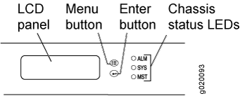
      Figure 2: LCD Panel in an EX4300 Switches Except EX4300-48MP and EX4300-48MP-S Switches
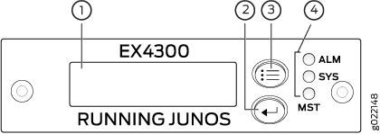
LCD Panel in an EX4300 Switches Except EX4300-48MP and EX4300-48MP-S Switches
        1

      LCD panel

        3

      LCD panel Menu button

        2

      LCD panel Enter button

        4

      Chassis status LEDs

      1. Press the Menu button until you see MAINTENANCE MENU. Then press the Enter button.

      2. Press Menu until you see ENTER EZSetup. Then press Enter.

        If EZSetup does not appear as an option in the menu, select Factory Default to return the switch to the factory default configuration. EZSetup is displayed in the menu of standalone switches only when a switch is set to the factory default configuration.

      3. Press Enter to confirm setup and continue with EZSetup.

  2. Connect the Ethernet cable from the Ethernet port on the PC to the switch.
    • EX2200, EX3200, or EX4200 switch—Connect the cable to port 0 (ge-0/0/0) on the front panel of the switch.

    • EX3300 switch—Connect the cable to the port labeled MGMT on the rear panel of the switch.

    • EX4300 switches except EX4300-48MP and EX4300-48MP-S switches—Connect the cable to the port labeled MGMT on the rear panel of the switch.

    • EX4500 or EX4550 switch—Connect the cable to the port labeled MGMT on the front panel (LCD panel side) of the switch.

    • EX4650 switches—Connect the cable to the port labeled CON on the rear panel of the switch.

    • EX6200 switch—Connect the cable to one of the ports labeled MGMT on the Switch Fabric and Routing Engine (SRE) module in slot 4 or 5 in an EX6210 switch.

    • EX8200 switch—Connect the cable to the port labeled MGMT on the Switch Fabric and Routing Engine (SRE) module in slot SRE0 in an EX8208 switch or on the Routing Engine (RE) module in slot RE0 in an EX8216 switch.

    These ports are configured as the DHCP server with the default IP address, 192.168.1.1. The switch can assign an IP address to the management PC in the IP address range 192.168.1.2 through 192.168.1.253.

  3. From the PC, open a Web browser, type http://192.168.1.1 in the address field, and press Enter.
  4. On the J-Web login page, type root as the username, leave the password field blank, and click Login.
  5. On the Introduction page, click Next.
  6. On the Basic Settings page, modify the hostname, the root password, and date and time settings:
    • Enter the hostname. This is optional.

    • Enter a password and reenter the password.

    • Specify the time zone.

    • Synchronize the date and time settings of the switch with the management PC or set them manually by selecting the appropriate option button. This is optional.

    Click Next.

  7. Use the Management Options page to select the management scenario:
    Note:

    On EX2300 and EX3400 switches, you cannot create a new VLAN for management.

    On EX4500, EX6210, and EX8200 switches, only the out-of-band management option is available.

    • Configure in-band management. In in-band management, you configure a network interface or an uplink module (expansion module) interface as the management interface and connect it to the management device.

      In this scenario, you have the following two options:

      • Use the automatically created VLAN default for management—Select this option to configure all data interfaces as members of the default VLAN. Specify the management IP address and the default gateway.

      • Create a new VLAN for management—Select this option to create a management VLAN. Specify the VLAN name, VLAN ID, management IP address, and default gateway. Select the ports that must be part of this VLAN.

    • Configure out-of-band management—Configure the management port. In out-of-band management, you use a dedicated management channel (MGMT port) to connect to the management device. Specify the IP address and gateway of the management interface. Use this IP address to connect to the switch.

  8. Click Next.
  9. On the Manage Access page, you can select options to enable Telnet, SSH, and SNMP services. For SNMP, you can configure the read community, location, and contact.
  10. Click Next. The Summary screen displays the configured settings.
  11. Click Finish. The configuration is committed as the active switch configuration.
    Note:

    After the configuration is committed, the connectivity between the PC and the switch might be lost. To renew the connection, release and renew the IP address by executing the appropriate commands on the management PC or by removing and reinserting the Ethernet cable.

  12. (For EX4500 switches only) In the CLI, enter the request chassis pic-mode intraconnect operational mode command to set the PIC mode to intraconnect.

You can now log in by using the CLI or the J-Web interface to continue configuring the switch.

If you use the J-Web interface to continue configuring the switch, the Web session is redirected to the new management IP address. If the connection cannot be made, the J-Web interface displays instructions for starting a J-Web session.

Release History Table
Release
Description
19.2R1
Starting in Junos OS Release 19.2R1, J-Web supports EX4650 switches.