Validation Framework
Extensive testing of best practice architectures is the key to the Juniper Validated Design program. JVDs qualify and quantify these best practice architectures, allowing you to know exactly what you're buying and to spend your time deploying and managing your network instead of designing it.
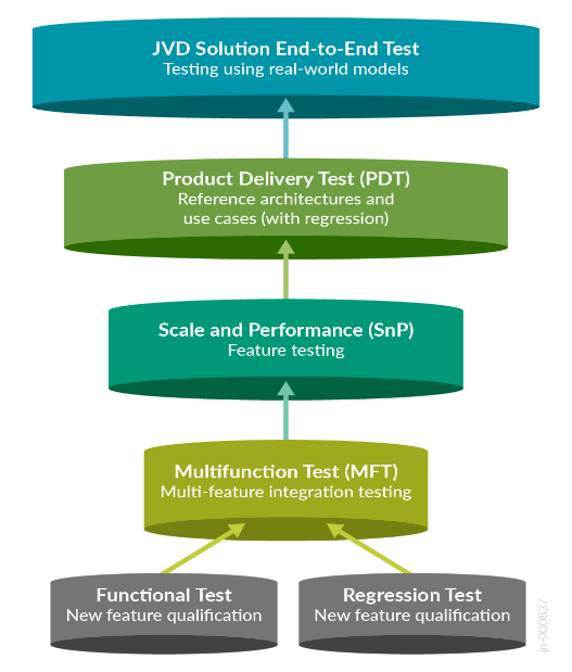
JVDs employ a layered testing approach to deliver reliability and repeatability. Individual features receive functional testing. Multifunction testing builds on this functional testing to see if multiple features work together. Product delivery testing builds upon multifunctional testing to validate that these features combined perform as expected for tested use cases, and JVD testing builds upon product delivery testing by testing multiple products together (including third-party integrations where appropriate) to ensure that all these products combined make an industry-leading solution.
Testing with real-world applications and traffic provides more accurate data regarding performance and response to different configurations. The standardized nature of JVDs ensures the same network architecture is deployed in multiple testing environments, and the use of JVDs by multiple customers allows for any lessons learned in production deployments to rapidly benefit all JVD customers. The more JVDs that are deployed worldwide, the greater the value they provide to all.
Test Bed
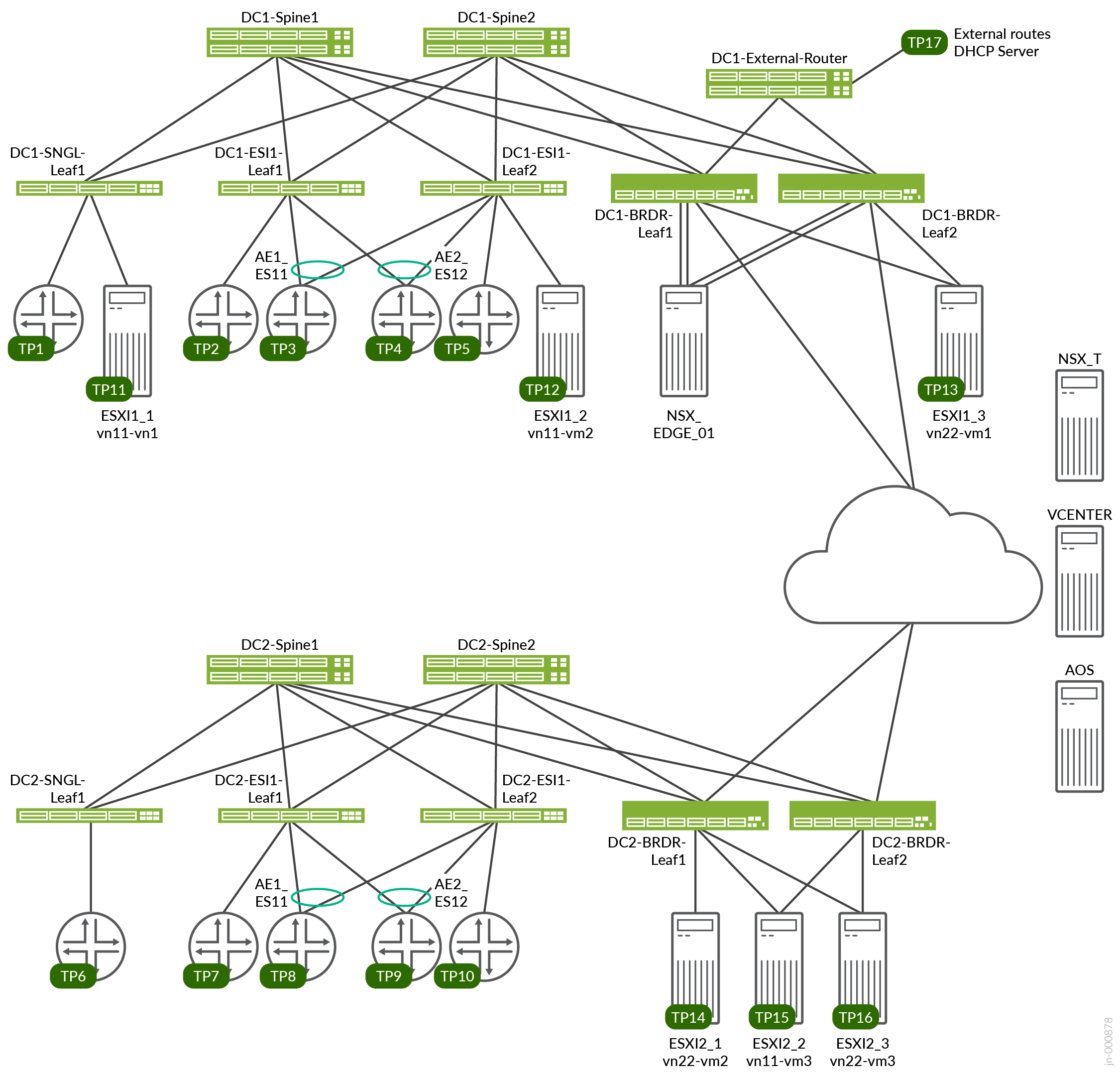
The test bed environment consists of two 3-stage EVPN/VXLAN fabric (DC1 and DC2) with Juniper Apstra with two ESI Server leaf switches, one single Server leaf (non-ESI), and two border leaf switches connected to two spines. The JVDE steps covered in this document to set up NSX-T refer to one of the DC (DC1 blueprint) as an example. However, the DC2 setup also follows a similar setup for the NSX-T configuration, but this is not shown for document brevity.
VMware NSX-T manager is hosted on VM ESXi managed by VMware Vsphere. VMware NSX-T edge switch (NSX_EDGE_01) is hosted as VM on the ESXi, connecting the two border leaf switches for left uplink (to border leaf switch one), right uplink (to border leaf switch two), and overlay (multi-homed).
The second three-stage DC (DC2 Blueprint) setup is DCI connected (using Layer 2 stretch) to the DC1 to test for remote VMs on separate Pods can be reached. The DCI connectivity is out of the scope of this JVDE document and will be covered separately in another JVDE.
The VDS in DC2 was created similarly to the steps explained in this JVDE and the hosts (ESXI2_1, ESXI2_2 and ESXI2_3) as shown in Figure 2 was also added to NSX-T so that the VMs in DC2 could be reached from DC1 VMs which use the same logical segments (vn11, vn22).
VRF Characteristics
RED VRF
- VLANs 400–649 with IRB v4/v6
- on DC1-SNGL-LEAF1 single access port
- on DC1-ESI-LEAF1 single access port, AE1 and AE2
- on DC1-ESI1-LEAF2 single access port, AE1 and AE2
- on DC1-BRDR-LEAF1 to distribute routes to external-router
- on DC1-BRDR-LEAF2 to distribute routes to external-router
- VLANs 400–649 on each test port with 10 unique MAC/IP per VLAN
- DHCP client on TP3
- External DHCP server on TP17
Blue VRF
- VLANs 3500–3749 with IRB v4/v6
- on DC1-SNGL-LEAF1 single access port
- on DC1-ESI-LEAF1 single access port, AE1 and AE2
- on DC1-ESI1-LEAF2 single access port, AE1 and AE2
- on DC1-BRDR-LEAF1 to distribute routes to external-router
- on DC1-BRDR-LEAF2 to distribute routes to external-router
- VLANs 3500–3749 on each test port with 10 unique MAC/IP per VLAN
- DHCP client on TP3, TP4, TP5
- External DHCP server on TP2
Platforms / Devices Under Test (DUT)
| Devices Under Test (Validated Devices) | |||
|---|---|---|---|
| Solution | Server Leaf Switches | Border Leaf Switches | Spine |
| 3-stage EVPN/VXLAN (ERB) | QFX5120-48Y-8C | QFX5130-32CD | QFX5220-32CD |
| QFX5110-48S | QFX5700 | QFX5120-32C | |
| ACX7100-48L | |||
| ACX7100-32C | |||
| PTX10001-36MR | |||
| QFX10002-36Q | |||
Test Bed Configuration
Contact Juniper or your Juniper account representative to obtain the full archive of the test bed configuration used for this JVD.