Use Case and Reference Architecture
This JVDE utilizes an edge-routed bridging (ERB) network architecture. ERB uses lean spines that only perform IP forwarding and do not terminate VXLAN tunnel endpoints (VTEPs). This approach allows for spine switches with simpler configurations and reduced demands leading to higher network stability.
In an ERB architecture, leaf switches focus on learning and advertising the local MAC addresses to other remote switches through the BGP EVPN control plane. This means leaf switches can discover all the “remote” hosts without flooding the overlay with ARP or ND requests. Border Leaf switches serve as the gateway to external networks. With this design philosophy, in this document, the VMware NSX-T edge node terminates on the border leaf switches.
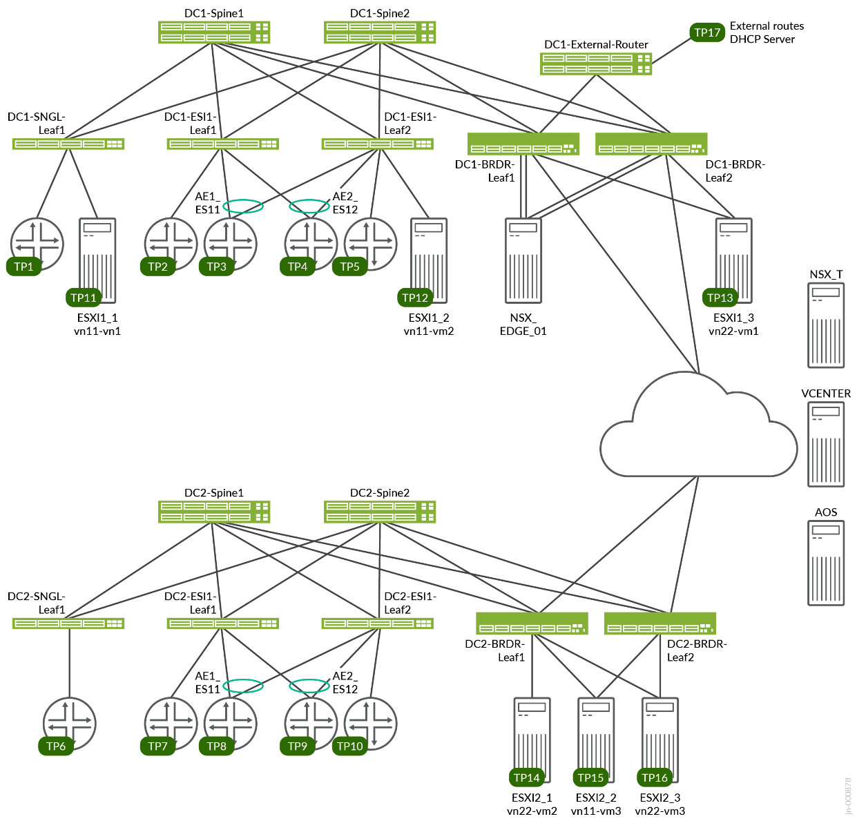
This JVDE is built upon the 3-Stage Data Center Design with Juniper Apstra JVD, which is the underlying network fabric for the purposes of this document. The underlying JVD network uses Juniper QFX, PTX, and ACX Series switches, which are managed by Juniper Apstra. Figure 1 depicts the topology of the 3-Stage Data Center Design with Juniper Apstra JVD and is referenced throughout this JVDE.
VRF Characteristics:
RED VRF
- VLANs 400–649 with IRB v4/v6
- on DC1-SNGL-LEAF1 single access port
- on DC1-ESI-LEAF1 single access port, AE1 and AE2
- on DC1-ESI1-LEAF2 single access port, AE1 and AE2
- on DC1-BRDR-LEAF1 to distribute routes to external-router
- on DC1-BRDR-LEAF2 to distribute routes to external-router
- VLANs 400–649 on each test port with 10 unique MAC/IP per VLAN
- DHCP client on TP3
- External DHCP server on TP17
Blue VRF
- VLANs 3500–3749 with IRB v4/v6
- on DC1-SNGL-LEAF1 single access port
- on DC1-ESI-LEAF1 single access port, AE1 and AE2
- on DC1-ESI1-LEAF2 single access port, AE1 and AE2
- on DC1-BRDR-LEAF1 to distribute routes to external-router
- on DC1-BRDR-LEAF2 to distribute routes to external-router
- VLANs 3500–3749 on each test port with 10 unique MAC/IP per VLAN
- DHCP client on TP3, TP4, TP5
- External DHCP server on TP2
Juniper Hardware and Software Components
For this solution, the Juniper products and software versions are listed below. The listed architecture is the recommended base representation for the validated solution. As part of a complete solutions suite, we routinely swap hardware devices with other models during iterative use case testing. Each platform also goes through the same tests for each specified version of Junos OS.
Juniper Hardware Components
The following switches are tested and validated to work with the 3-Stage Fabric with Juniper Apstra JVD in the following roles:
| Validated Devices and Positioning | |||
|---|---|---|---|
| Solution | Server Leaf Switches | Border Leaf Switches | Spine |
| 3-stage EVPN/VXLAN (ERB) | QFX5120-48Y-8C* | QFX5130-32CD* | QFX5220-32CD* |
| QFX5110-48S | QFX5700 | QFX5120-32C | |
| ACX7100-48L | |||
| ACX7100-32C | |||
| PTX10001-36MR | |||
| QFX10002-36Q | |||
* marked are baseline devices
| Baseline Devices and Positioning | |||
|---|---|---|---|
| Juniper Devices | Role | Hostname | Software or Image Version |
| QFX5220-32CD | Spine | dc1-spine1 and dc1-spine2 | Junos OS Evolved 22.2R3-S3.13 |
| QFX5120-48Y | Server Leaf | dc1-single-001-leaf1, dc1-esi-001-leaf1, and dc1-esi-001-leaf2 | Junos OS 22.2R3-S3.18 |
| QFX5130-32CD | Border Leaf | dc1-border-001-leaf1 and dc1-border-001-leaf2 | Junos OS Evolved 22.2R3-S3.13 |
The 3-stage qualified devices are validated against Junos OS 22.2R3-S3 release, see Feature list for more information.
| Juniper Software | |
|---|---|
| Juniper Products | Software or Image version |
| Juniper Apstra | AOS 4.2.1-207 |
VMware Software Components
For the purposes of this document, the VMware products and their software versions are below. The listed architecture is the recommended base representation for the validated solution. As part of a complete solutions suite, we routinely swap hardware devices with other models during iterative use case testing. Each platform also goes through the same tests for each specified version of Junos OS.
| VMware Products | |
|---|---|
| VMware Products | Software or Image Version |
| NSX-T Edge | nsx-edge-3.2.1.0.0.19232403 |
| NSX-Manager | Version: 3.2.0.1.0.19232396 |
| vSphere Client | Version: 7.0.2 |
| ESXi | VMware ESXi, 7.0.2, 17630552 or later |
Installing and upgrading of VMware components are not within the scope of this document.
Apstra Resources: ASN, Fabric, and Loopback IP Address
Apstra resources for this JVDE are listed below. Resource assignments are based on the 3-Stage Data Center Design with Juniper Apstra JVD. To learn more about creating Resources in Apstra, see the Juniper Apstra User Guide.
| Resources | Range | |
|---|---|---|
| Fabric IP | 10.0.1.0/24 | |
| Fabric Loopback IP | 192.168.255.0/24 | |
| ASN | 64512 – 64999 | |
| Routed Interface IP to NSX-T Edge Node (Border Leaf1to Left Link) | 192.168.100.0/24 | |
| Routed Interface IP to NSX-T Edge Node (Border Leaf2 – Right Link) | 192.168.200.0/24 | |
| VLAN from Border Leaf1 to NSX-T Edge Node (Left) | 100 | |
| VLAN from Border Leaf1 to NSX-T Edge Node (Right) | 200 | |
VMware NSX-T Manager Resources
VMware resources for the validated solution are listed below.
| Resources | Range | Notes |
|---|---|---|
| TEP Pool | 10.10.10.0/24 | Assigned by NSX-T manager to ESXi Host |
| vn11 | 10.9.11.0/24 | Assigned to VMs created in this document |
| vn22 | 10.9.22.0/24 | Assigned to VMs created in this document |
| ASN | 65000 | ASN for T0 Gateway |
| Loopback IP of T0 Gateway | 10.0.0.1/32 | Assigned while configuring T0 Gateway |
| Interface IP for T0 Interfaces to Border Leaf1 | 192.168.100.0/24 | Assigned while configuring T0 Gateway |
| Interface IP for T0 Interfaces to Border Leaf2 | 192.168.200.0/24 | Assigned while configuring T0 Gateway |
| Uplink1 segment VLAN | 100 | Uplink VLAN for Left |
| Uplink2 Segment VLAN | 200 | Uplink VLAN for Right |