Solution Architecture
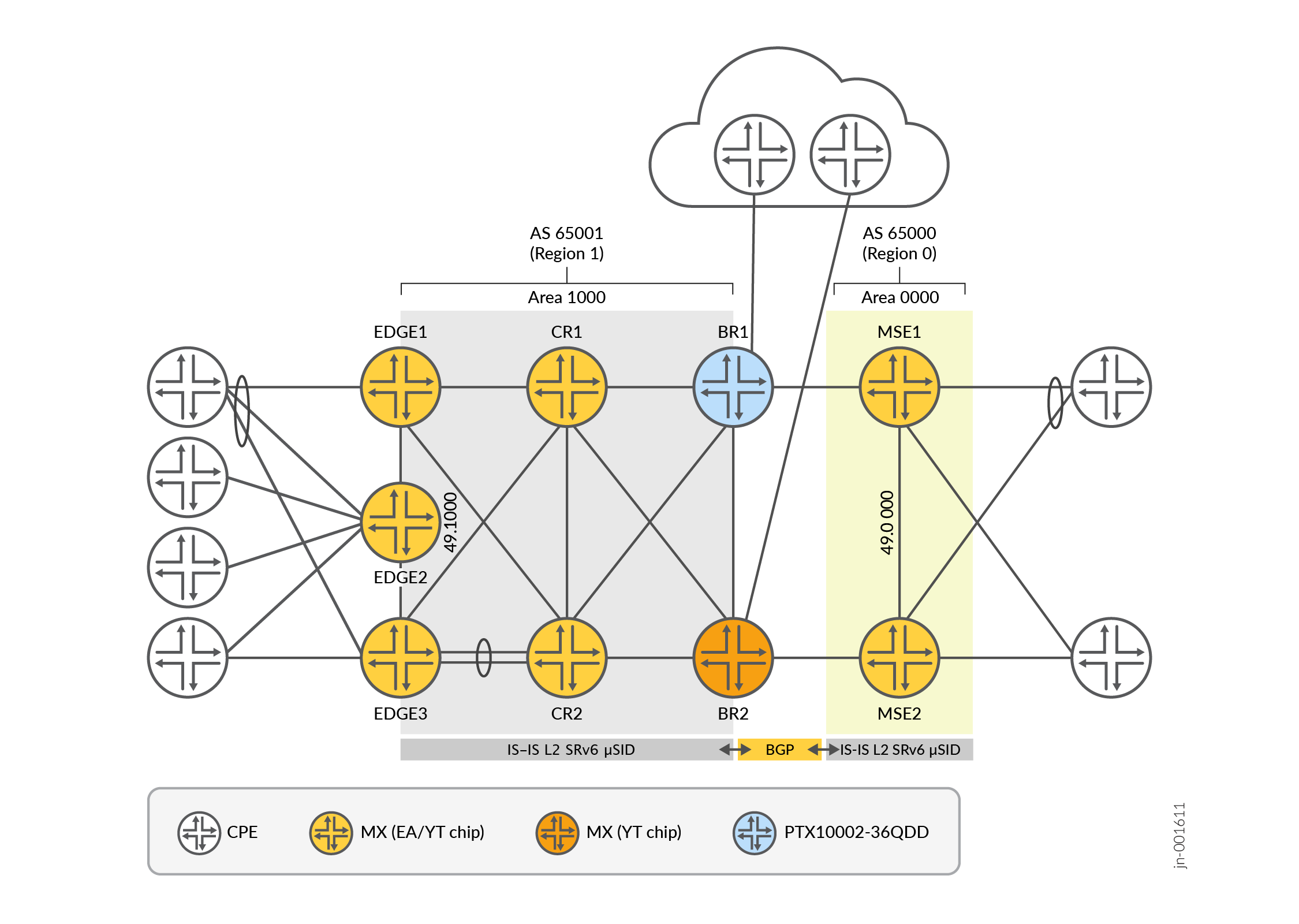
JVD Lab Topology
Platform Positioning
This JVD is evaluated and validated on the following platforms.
The Devices Under Test (DUT) are used with helper devices. However, the helper device’s functionality is not evaluated. They facilitate test execution.
- Edge Node:
- EDGE1 (DUT) – MX480 with MPC7E 3D 40XGE (Trio 4: EA chip)
- EDGE2 (DUT) – MX480 with MPC7E 3D 40XGE (Trio 4: EA chip)
- EDGE3 (DUT) – MX480 with MPC10E 3D MRATE-15xQSFPP (Trio 5: ZT chip)
- Core Router:
- CR1 (DUT) – MX10004 with JNP10K-LC9600 (Trio 6: YT chip)
- CR2 (DUT) – MX2010 with MPC11E 3D MRATE-40xQSFPP (Trio 5: ZT chip)
- Border Router:
- BR1 (DUT) – PTX10002-36QDD (Express 5: BX chip)
- BR2 (DUT) – MX304 (Trio 6: YT chip)
- Multi-Service Edge
- MSE1 (DUT) – MX480 with MPC10E 3D MRATE-10xQSFPP (Trio 5: ZT chip)
- MSE2 (DUT) – MX304 (Trio 6: YT chip)
- Customer Premises Equipment
- CPE1 (Helper) – MX240
- CPE2 (Helper) – MX240
- CPE3 (Helper) – MX240
- CPE4 (Helper) – MX240
- RT – IXIA (Helper) Tester device is used to generate traffic flow and increase network scale
Network Architecture
The network architecture of this JVD aligns with typical service provider architecture, where the network is divided into multiple domains. Domains in this SRv6 JVD use Autonomous Systems, with prefix leaking or summarization between domains.
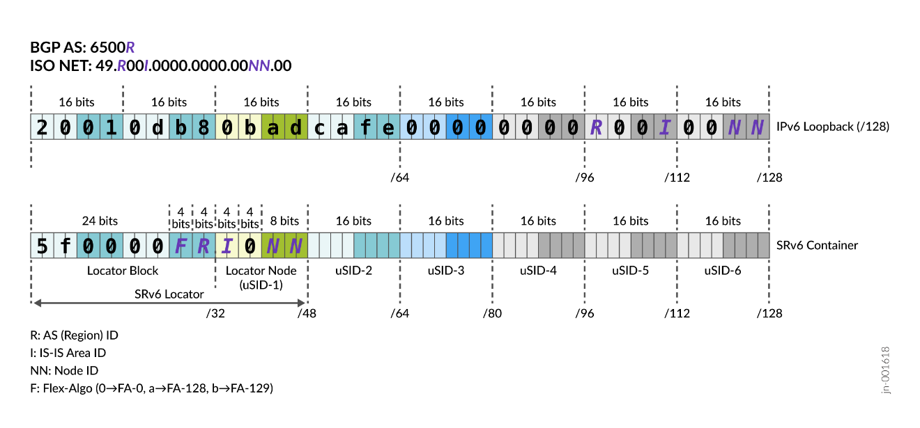
Addressing Scheme
This JVD uses IPv6 infrastructure addresses exclusively. No IPv4 infrastructure addresses are configured (i.e., no IPv4 addresses on loopbacks or links). IPv4 addressing might be present in the VPN context only (i.e., on PE-CE links, or on loopbacks within VRFs), to validate that both IPv4 and IPv6 VPNs can be transported across IPv6-only SRv6 underlay transport. 4-byte (32-bit) identifiers are used for Router ID, BGP Cluster ID, as well as BGP Route Distinguishers.
To minimize operational and management efforts, IPv6 Link Local Addressing (LLA) is used in this JVD. Therefore, no global IPv6 link addresses are assigned. On the other hand, for loopbacks, SRv6 locator blocks and SRv6 locators, a well-organized, structured IPv6 addressing scheme is used. Similarly, IS-IS area IDs and BGP autonomous systems use structured numbering schemes. SRv6 locators use the IANA-assigned prefix 5f00::/16 (RFC 9602). There are many possible ways for such allocation. The allocation might differ from deployment to deployment, depending on actual requirements. Figure 2 outlines the example allocation used in the JVD.
IS-IS
Main characteristics of IS-IS are:
- IS-IS type point-to-point (P2P) links use IPv6 Link Local Address (LLA) addressing. No global IPv6 addresses appear on links.
- All links use an increased MTU (IFD MTU: 9192, inet6/iso MTU: 9106).
- IFD hold-timers (Juniper Networks MX Series Routers, Juniper Networks PTX Series Routers) and IFD exponential damping (MX Series, PTX Series) are enabled to suppress interface flapping, minimizing IS-IS churn when interface flaps
- IS-IS Level 2 with wide metrics is only used. Level 1 is disabled throughout the network.
- Only IS-IS Hello packets are sent with maximum MTU (strict Hello padding) to continuously verify MTU availability. Remaining IS-IS packets (LSP, CSNP, PSNP) use a standard maximum size of 1492 octets.
- IPv6 unicast topology is explicitly enabled. Enabling separate topologies is beneficial in migration scenarios that support both IPv4 (MPLS) and IPv6 (SRv6). Using separate IPv4 unicast topology (which is the default topology) and IPv6 unicast topology (explicitly configured topology) support non-congruent networks (some links are only IPv4, some links only IPv6, some links both IPv4 and IPv6).
In this JVD, IPv4 is not used.
- Overload metrics (for IS-IS neighbors and internal or external prefixes) with a timeout are enabled. When the routing process restarts, high metrics are advertised until the configured timeout expires.
- ISO NET addresses are configured in each IS-IS process (no ISO NET addressing on loopbacks).
- Topology Independent Loop Free Alternates (TI-LFA) is enabled (both link and node protection) with ‘soft’ node-protection flavor (i.e., during backup path calculation, instead of removing the protected node from the topology, link metrics to the protected node are increased to the MAX-1 value).
- Micro-Loop Avoidance (MLA) is enabled with default timer settings.
- IS-IS adjacencies are protected with BFD. On aggregated interfaces (LAG), instead of using BFD to protect IS-IS adjacencies, per-member link BFD sessions are used to protect LACP (micro-BFD).
- Both Hello and LSP authentication are deployed, using the HMAC-SHA-1 authentication algorithm and the IS-IS enhanced option.
- Each link has three metrics:
- IGP metric (derived automatically from reference bandwidth 1 Tbps)
- TE metric (manually configured)
- Delay metrics (based on dynamically measured link delay through a Two-Way Active Measurement Protocol - TWAMP light)
- TWAMP light server uses the following timestamping methods,
available in Junos OS Release 24.2, to achieve the highest possible
accuracy (TWAMP light client for link delay measurements always use
packetIO timestamp):
- Juniper Networks PTX Series Routers: PFE timestamping (medium accuracy)
- Juniper Networks MX Series Routers: mKernel or packetIO, depending on the line card (low accuracy)
- TE and delay metrics are distributed using Application Specific Link Attribute (ASLA) TLV for the Flex-Algo application.
- Three Flex-Algos are deployed across the network:
- Flex-Algo 0: using IGP metrics (this is the default Flex-Algo)
- Flex-Algo 128: using delay metrics
- Flex-Algo 129: using TE metrics
- Each Flex-Algo has its own Node (µN) and unprotected adjacency SIDs (µA). In the core domain, static unprotected adjacency SID are used (the same value is used across reboots).
- IS-IS uses export policy to export specific prefixes with specific IS-IS tags, as outlined in Table 1 . Using IS-IS tags simplifies IS-IS import export policies.
- IS-IS uses an import policy to set the FIB installation priority (loopbacks and locators are high), and to enable or disable backup path calculation for specific prefix groups.
- A maximum limit (for example, 3000 prefixes) of redistributed prefixes is set to avoid overflowing the IS-IS database with a large number of prefixes that might be redistributed accidentally. When the limit of redistributed prefixes is reached, IS-IS does not enter the overload state but stops the redistribution of additional prefixes.
- To avoid accidental redistribution into IS-IS from other routing protocols, when users modify IS-IS export policies, redistribution from BGP, OSPF, and static is explicitly disabled.
| Value | Type | Synopsis |
|---|---|---|
| 101 | tag1 | SRv6 Locators |
| 102 | tag1 | Loopbacks |
| 103 | tag1 | Links |
| 201 | tag1 | SRv6 locator aggregate |
| 202 | tag1 | Loopback aggregate |
BGP
In Figure 3, the BGP design is based on a classical router-reflector design, with CR nodes functioning as a pair of BGP route reflectors.

Main characteristics of BGP:
- BGP uses an external Router ID as a tiebreaker for path selection
- The system advertises local service routers from the main routing table (not from the service routing tables)
- BGP export policies apply to exported local service prefixes
- BGP uses precision timers
- BGP uses BGP error tolerance extensions
- BGP uses multi-path list next-hop structures
- BGP uses RFC 8950-compliant IPv6 next hop encoding for IPv4 NRLIs (AFI=1) to allow interoperability with 3rd party vendors
- TCP Authentication Option (AO) is enabled on all the BGP sessions
- TCP Maximum Segment Size (MSS) increased for better BGP packing
- Single-hop eBGP sessions, like single-hop IS-IS adjacencies, are protected with BFD
- BGP exchanges SRv6 locator summaries and loopback summaries between AS's and redistributes them into IS-IS
- Network Layer Reachability Information (NLRIs) are enabled on BGP sessions, as per Table 2
| NLRI Name | AFI/SAFI | Edge | CR | BR | MSE |
|---|---|---|---|---|---|
| IPv4 unicast | 1/1 | R | R | R | |
| IPv6 unicast | 2/1 | R | R | R | R |
| VPN IPv4 unicast | 1/128 | R | R | R | R |
| VPN IPv6 unicast | 2/128 | R | R | R | R |
| EVPN | 25/70 | R | R | R | |
| RT constraints | 1/132 | R | R | R | R |
RT constraints NLRI has disabled next-hop resolution. This NLRI is pure control-plane NLRI, not used for forwarding, therefore does not require next-hop resolution for forwarding. Disabling next-hop resolution for this NRLI slightly improves BGP convergence by always accepting the NLRI, regardless of the next-hop status (reachable or not).
All other NLRIs are enabled to accept or send SRv6 service SIDs.
On BGP route reflectors, there are small changes in BGP settings compared to other routers. The changes in BGP settings are:
- next-hop resolution is disabled for all NLRIs (RRs reflect NLRIs regardless of whether the next-hop is reachable or not. This approach improves overall BGP convergence.)
- RT constraints NLRI advertises a default RT constraint (for example, send me all prefixes, regardless of RT)
eBGP sessions between regions exchange loopback summaries and SRv6 locators between regions and carry RT constraints and Service NLRIs. The receiving Autonomous System Boundary Routers (ASBRs) generate SRv6 locator summaries. These eBGP sessions terminate on global IPv6 addresses of links that interconnect regions. For proper SRv6 next-hop resolution with dynamic tunnels, configure the eBGP sessions as multi-hop, and ensure that next-hop remains unchanged (classical Option C architecture).
Services
Multiple services are implemented at the top of the network, as outlined in Figure 4 .
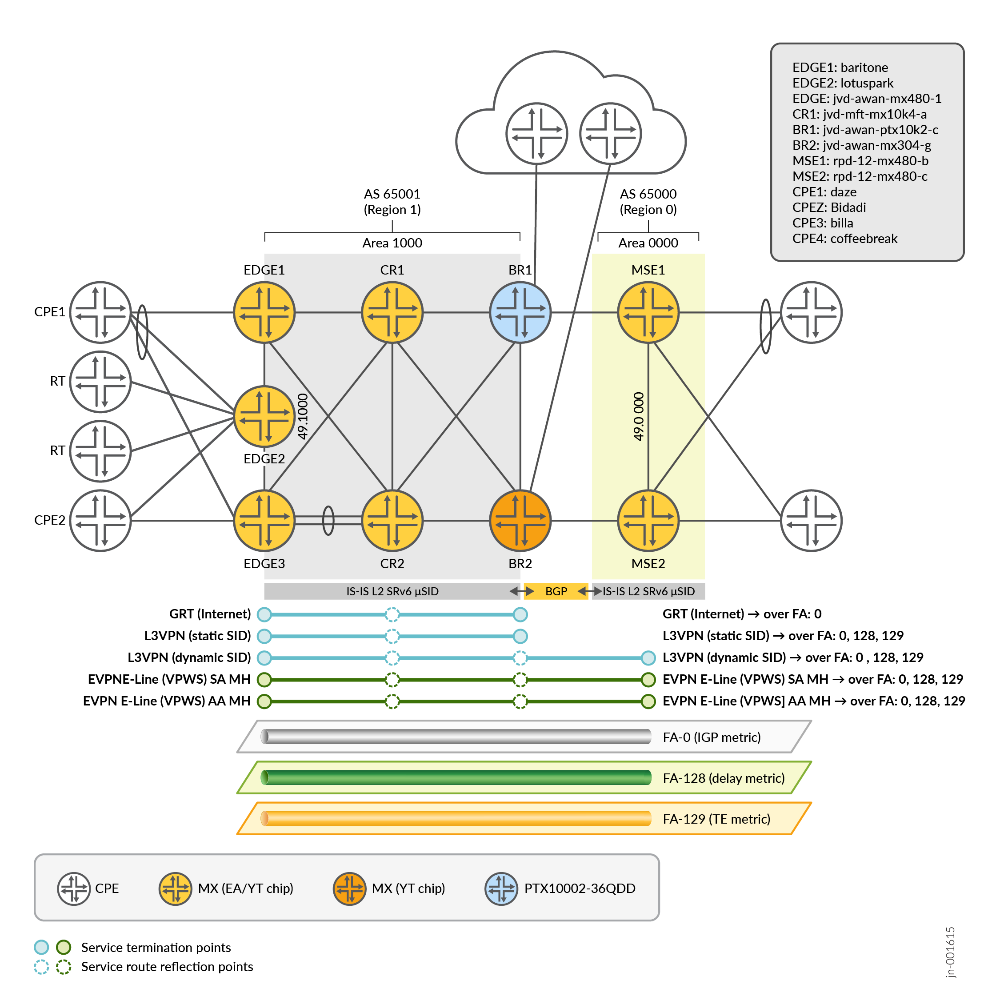
The types of traffic flows represented in the topology include:
- Global Routing Table (GRT) between EDGE and BR that carry IPv4 and IPv6 Internet routes, using dynamically allocated µDT46 service SID (single-service SID for all routes). GRT traffic uses only the default Flex-Algo (Flex-Algo 0) as a transport underlay.
- L3VPN (SAFI=128) between EDGE and BR that carry IPv4 and IPv6 VPN traffic uses per-VRF manually assigned µDT46 service SID. Each VRF maps to a specific Flex-Algo underlay by deriving per-VRF service SID from the SRv6 locator associated with the given Flex-Algo. A small set of prefixes within the VRF has a per-prefix, manually assigned µDT46 service SID. The SID is derived from a different SRv6 locator to map these prefixes to a different Flex-Algo underlay.
- L3VPN (SAFI=128) between EDGE, BR, and MSE that carry IPv4 and IPv6 VPN traffic, use per-VRF, dynamically assigned µDT46 service SID. Each VRF maps to a specific Flex-Algo underlay by deriving the per-VRF service SID from SRv6 locator associated with the given Flex-Algo. A small set of selected prefixes within the VRF has a per-prefix, dynamically assigned µDT46 service SID, derived from a different SRv6 locator to map these prefixes to a different Flex-Algo underlay. The MSE L3VPN service requires SRv6 SID resolution through a locator prefix announced by BGP. These prefixes do not have an IS-IS SRv6 locator TLV, so the SRv6 SID resolution fails. The MSE implements the SRv6 dynamic-tunnel feature to allow SRv6 SID resolution without IS-IS SRv6 locator TLV.
- EVPN E-Line (VPWS) with single-active multihoming between EDGE and MSE uses statically and dynamically assigned µDX2 service SID. Each E-Line maps to a specific Flex-Algo underlay by deriving service SIDs from the SRv6 locator associated with the given Flex-Algo.
- EVPN E-Line (VPWS) with all-active multi-homing between EDGE and MSE uses statically and dynamically assigned µDX2 service SID. Each E-Line maps to a specific Flex-Algo underlay by deriving service SIDs from the SRv6 locator associated with the given Flex-Algo.
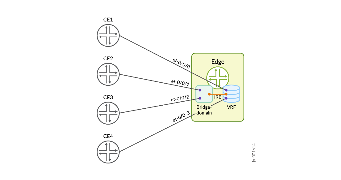
L3VPN might have direct PE-CE interfaces, as well as IRB as PE-CE interfaces, as outlined in Figure 5 .
Solution Validation Requirements
This JVD validates an end-to-end network architecture and design using SRv6 underlay with GRT, L3VPN, and EVPN E-Line services at scale under multiple stress conditions to emulate Business as Usual Operations (BAU OPS).
- Validate Global Routing Table (GRT) IPv4 and IPv6 internet routes, using dynamically allocated µDT46 service SID (single service SID for all routes)
- Validate L3VPN (SAFI=128) carrying IPv4 and IPv6 VPN traffic, using per-VRF, statically (manually) or dynamically assigned µDT46 service SID
- Validate IRB interface as a PE-CE interface in an SRv6-based L3VPN
- Validate dynamic tunnel creation to aid next-hop resolution of L3VPN prefixes without the presence of an IS-IS SRv6 Locator TLV
- Validate EVPN E-Line (VPWS) with single-active and all-active multihoming using statically (manually) and dynamically assigned µDX2 service SID
- Validate per instance SRv6 locator-based mapping of L3VPN and EVPN E-Line (VPWS) services to different SRv6 Flex-Algos
- Validate per prefix SRv6 locator-based mapping of L3VPN prefixes to different SRv6 Flex-Algos
Key Measurements
As a part of JVD testing, record the following items under the scaled environment.
- Link failure event (should be ≤50ms)
- Link restoration event (should be ≤50ms)