Validation Framework
This JVD addresses the modernization of the transport layer. A crucial aspect of this solution is to test the capabilities of Juniper 400G Coherent Optics (JCO400). Major technical attributes include:
- For Amplified Links:
- Minimum receives Optical Signal-to-Noise Ratio
- Maximum receives Chromatic Dispersion
- For Unamplified Links:
- RX Sensitivity
- Telemetry
- Junos and Junos Evolved Software Support
- Configurability
- Performance Monitoring
Test Bed
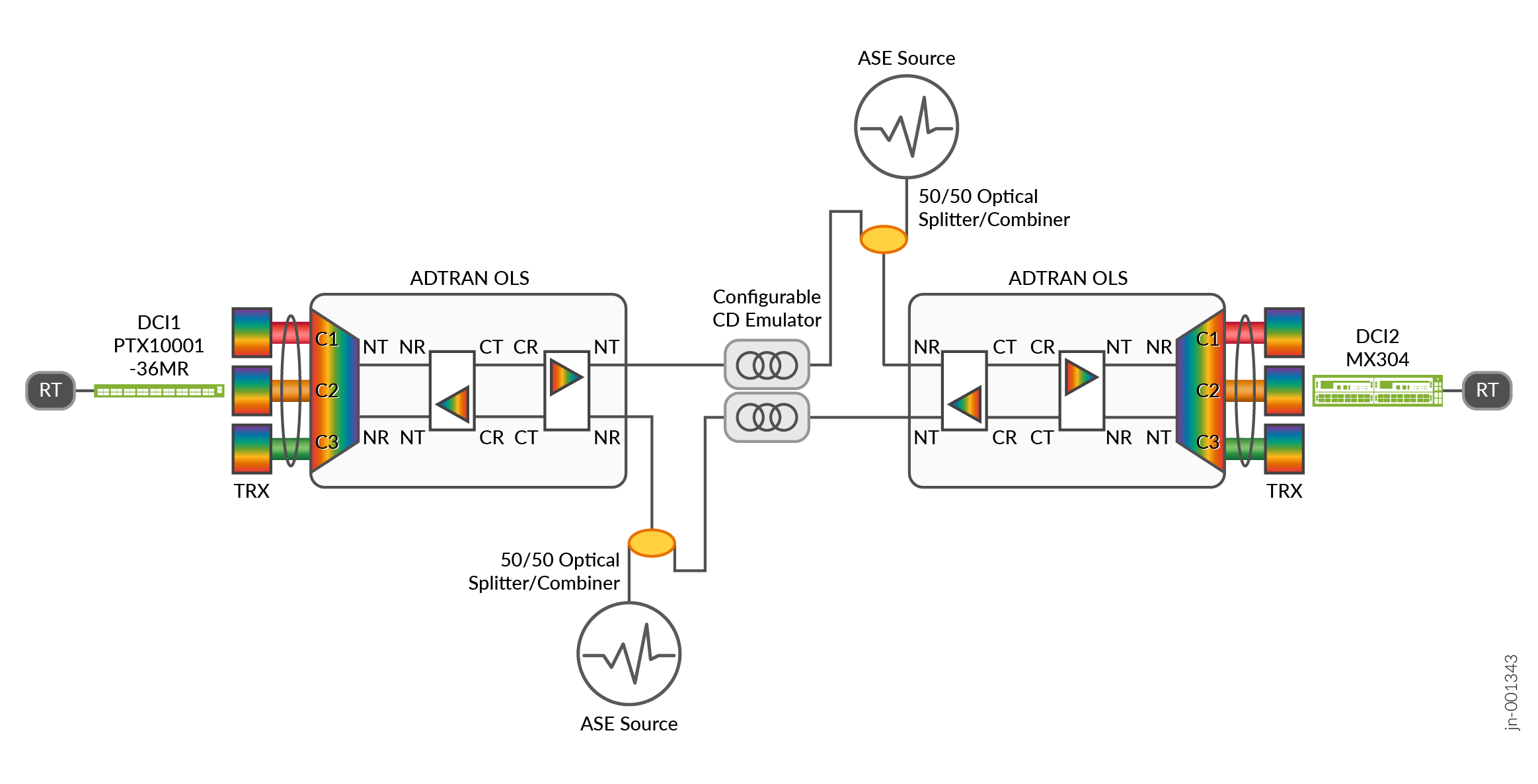
Figure 1 shows the physical topology of an amplified test bed. Three coherent optical transceivers (TRX) are used in both DCI1 and DCI2 routers. All transceivers and the reconfigurable optical add-drop multiplexer (ROADM) ports are tuned to a specific wavelength or frequency. All three signals with different wavelengths are multiplexed into a single pair of fiber. For most test cases, one transceiver is designated as the unit under test, while the other two transceivers as aggressors.
It is important to note that an amplifier adds noise to the signal. Therefore, the Optical Signal-to-Noise ratio is reduced on every Line System/Amplifier Hop. This is emulated in the validation by adding an amplified spontaneous emission (ASE) as a source of noise.
Another important factor is that the fiber optic cable disperses light signal. This is called Chromatic Dispersion (CD). This effect can be compensated by the transceiver’s digital signal processor (DSP), but only to a certain limit. Chromatic dispersion is directly proportional to the fiber optic cable distance. Thus, chromatic dispersion emulators are used to emulate fiber optic cable distance.
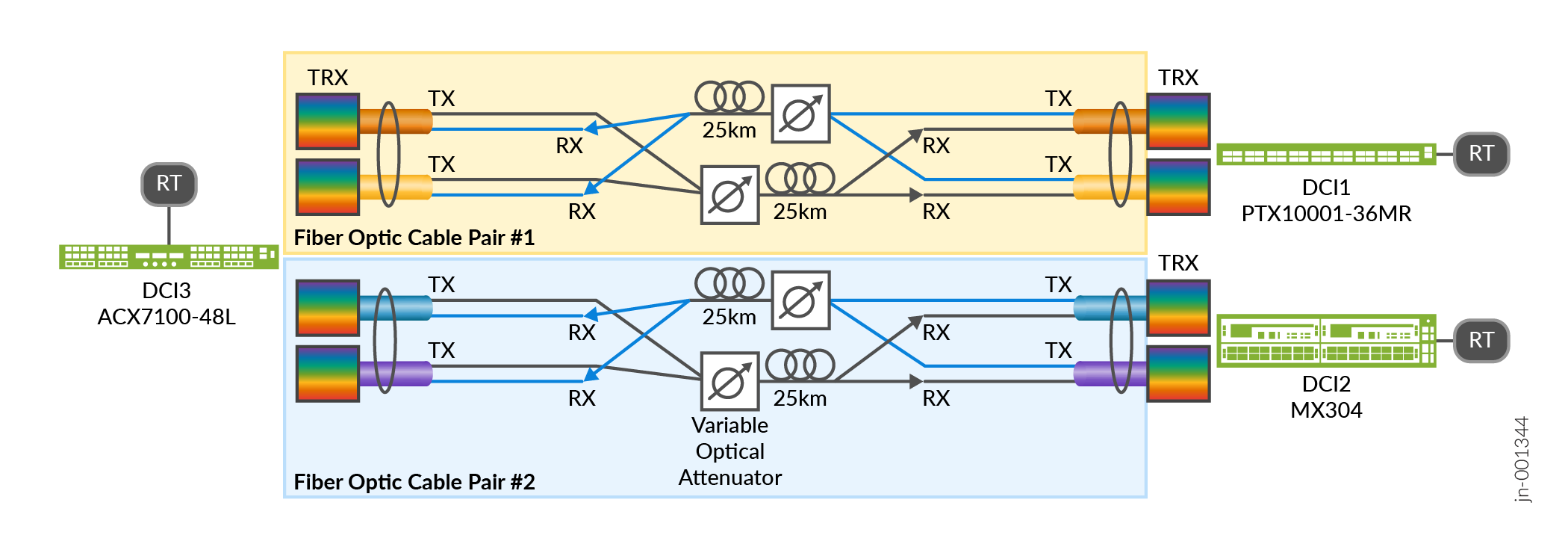
Figure 2 shows the physical topology of an unamplified test bed. There are two pairs of fiber optical cables. Each pair carries two wavelengths. The wavelengths are combined by using a 50/50 Optical Splitter/Combiner. Two coherent optical transceivers are used on DCI1 and DCI2 routers and 4 transceivers are used on DCI3. All transceivers are tuned to a specific wavelength or frequency.
For unamplified or dark fiber links, the design is limited by optical power. As light goes through fiber optic cable, some optical power is lost mainly due to light scattering by the fiber material. This Span Loss is the only factor to consider when designing unamplified links. The maximum span loss allowed, or the link budget is limited by the Transmit Power and Receiver Sensitivity of the optical transceiver.
To emulate span loss, a Variable Optical Attenuator (VOA) is used.
Platforms / Devices Under Test (DUT)
To review the software versions and platforms on which this JVD was validated by Juniper Networks, see the Validated Platforms and Software section in this document.
Test Bed Configuration
Configuration Template for Junos Evolved Platforms
interfaces {
    $INTERFACE_NAME$ {
        speed $PORT-SPEED$;
           number-of-sub-ports $NUMBER-OF-CHANNELS$;
           optics-options {
                        wavelength $WAVELENGTH$;
                        tx-power $TX-POWER$;
                }
    }
}For channelized interfaces, optics-options are configured on the first sub-port (et-x/y/z:0), not on the parent port (et-x/y/z). The speed and number-of-subports knobs are still configured under the parent port.
Configuration Template for Junos Platforms
chassis {
    fpc $FPC$ {
        pic $PIC$ {
            port $PORT$ {
                speed $PORT-SPEED$;
                         number-of-sub-ports $NUMBER-OF-CHANNELS$;
            }
        }
    }
}
interfaces {
    $INTERFACE_NAME$ {
                optics-options {
                        wavelength $WAVELENGTH$;
                        tx-power $TX-POWER$;
                }
    }
}For channelized interfaces, optics-options are configured on the first sub-port (et-x/y/z:0), not on the parent port (et-x/y/z).
Configuration Template for ADTRAN FSP3000C Open Line System
Amplifier: AM-S23L
Optical Multiplexer/Demultiplexer (Mux/Demux): RD-12RS
### The commands needs to be executed in sequence
.
set interface 1/$ROADM_SLOT_NUM$/n/oms oms carrier-power-management setpoint-psd -35
set interface 1/$ROADM_SLOT_NUM$/$CLIENT_PORT_NUM$/oms is-substates append mt
set interface 1/$ROADM_SLOT_NUM$/$CLIENT_PORT_NUM$/oms carrier-power-management powerset-configuration enable setpoint-psd -24
set interface 1/$ROADM_SLOT_NUM$/$CLIENT_PORT_NUM$/oms oms is-substates remove all
set fiber a-end 1/$ROADM_SLOT_NUM$/n z-end 1/$PREAMP_SLOT_NUM$/n
set fiber a-end 1/$PREAMP_SLOT_NUM$/c z-end 1/$BOOSTER_SLOT_NUM$/c
commit
### Assign one Arbitary_Service_Number per Client_Port per Center Frequency then configure multiple instances as per below template
set interface 1/alien/$ARBITARY_SERVICE_NUMBER$
set interface 1/alien/$ARBITARY_SERVICE_NUMBER$/otsi >>
set otsi $ARBITARY_SERVICE_NUMBER$ center-frequency $CLIENT_PORT_FREQUENCY_THZ$ bandwidth $CLIENT_PORT_BANDWIDTH_GHZ$
done
commit
set fiber a-end 1/alien/$ARBITARY_SERVICE_NUMBER$ z-end 1/$ROADM_SLOT_NUM$/$CLIENT_PORT_NUM$/
commit
set croma slc $ARBITARY_SERVICE_NUMBER$ >>
set slc-aendpoint path-node-number 2
set slc-zendpoint path-node-number 1
set slc-aendpoint slc-active-endpoint slc-resource-instance $DEGREENUMBER$
set slc-zendpoint slc-active-endpoint slc-resource-instance 1/alien/$ARBITARY_SERVICE_NUMBER$/otsi
done
commit
set croma slc $ARBITARY_SERVICE_NUMBER$  slc-zendpoint admin is
commit
run execute interface 1/$ROADM_SLOT_NUM$/n/oms oms carrier-power-management equalize
run execute interface 1/$ROADM_SLOT_NUM$/n/oms oms degree-span-equalization start-span-initialization
set croma slc $ARBITARY_SERVICE_NUMBER$ slc-aendpoint admin is
commit
run execute interface 1/$ROADM_SLOT_NUM$/$CLIENT_PORT_NUM$/oms oms carrier-power-management powerset
Contact your Juniper representative to obtain ADTRAN representative for support.
For full configurations used in this validation, see Juniper GitHub .