Solution Architecture
Solution Technical Overview
In the proposed solution the ACX7024 router acts as a fan-out device and the MX Series router is our choice for the PE-node and performs the following functions:
- Aggregation and multiplexing of traffic between multiple attached circuits at FO–PE link(s). Attached circuits may be either a plain Ethernet link or an aggregated Ethernet bundle.
-
Transparent L2 extension of a CE–PE link. Transparency of a fan-out device
manifests itself in both the data plane and the control plane:
- In the data plane, the fan-out device is oblivious to VLAN tags that are either locally significant between CE and PE (on what previously was a direct Layer 1 (L1) CE–PE connection), or globally significant between local and remote CEs (for example, when PE provides L2 bridging of the customer's frames with L2 circuits or other means).
-
In the control plane, the fan-out device is oblivious to L2 control protocols (L2CPs) that have significance or meaning to either the CE or the PE or both. The fan-out device does not interact with the customer's L2CPs and transparently forwards their protocol data units (PDUs) between the CE–FO link and the FO–PE link.
Note that there are L2CPs that are meant to be locally significant between link partners on an Ethernet link, this is discussed below.
- L2CP transparency is what differentiates the fan-out design from generic hierarchical network designs where the network elements at different levels of network hierarchy actively interact with each other in the control plane for various purposes such as topology discovery, maintenance, and recovery (LACP, STP, link state routing protocols), disseminating reachability information (routing protocols), active in-band connectivity monitoring (BFD, CFM, protocol keepalives), and so on.
- Propagation of L1 link state between CE and PE, and between local and remote CEs.
The following list of features and design decisions represent the technical summary of the solution which can be used as a basis for a deployment and extension of the solution towards other Juniper platforms if needed:
- The L1 state of a local CE-facing interface propagates to remote CE-facing interface, and vice versa.
- The CE-facing interface is agnostic of customer's VLAN tags.
- The FO–PE link that carries traffic from multiple customers uses the simplest link virtualization technique available, without a control channel.
- The fan-out device is reasonably transparent for L2 and other control protocols.
- The data plane is implemented in a segmented manner: CE–FO, FO–PE, PE–PE. That is, there are no end-to-end tunnels, L2 circuits, and that hop over the top of the network.
- Fault propagation is implemented in a segmented manner: CE–FO, FO–PE, PE–PE. That is, there is no targeted FO-to-FO propagation.
- PE–PE fault propagation uses existing underlying network's signaling such as a status TLV in LDP-signaled L2 circuits, route advertisement and withdrawal by routing protocols where L3 routed services are used, and so on.
- The fan-out device is an L2 extension of a PE (or PEs), thus doesn't perform local switching between CE facing ports, CE to CE communication always takes place through a PE device.
- Services provided on PEs can be point-to-point or multipoint L2 or L3 services. For example, vanilla IP routing, bridging, L2 VPNs (VPWS, VPLS, EVPN), and so on.
- Both in-band and out-of-band management options are available to manage the fan-out device.
- The FO's CE-facing physical interface (IFD) uses port-based CCC encapsulation.
- Asynchronous notification (means laser-off is allowed) is enabled on the FO's CE-facing IFD. This allows the L2 circuit and CFM MEP to control the CE-facing port's laser when it needs to signal a failure towards the CE.
- On the fan-out device, the local point-to-point L2 circuit bridges customer frames between the CE-facing the logical interface (IFL) on the attachment circuit and PE-facing IFL on the FO-PE link. There is no MAC address learning.
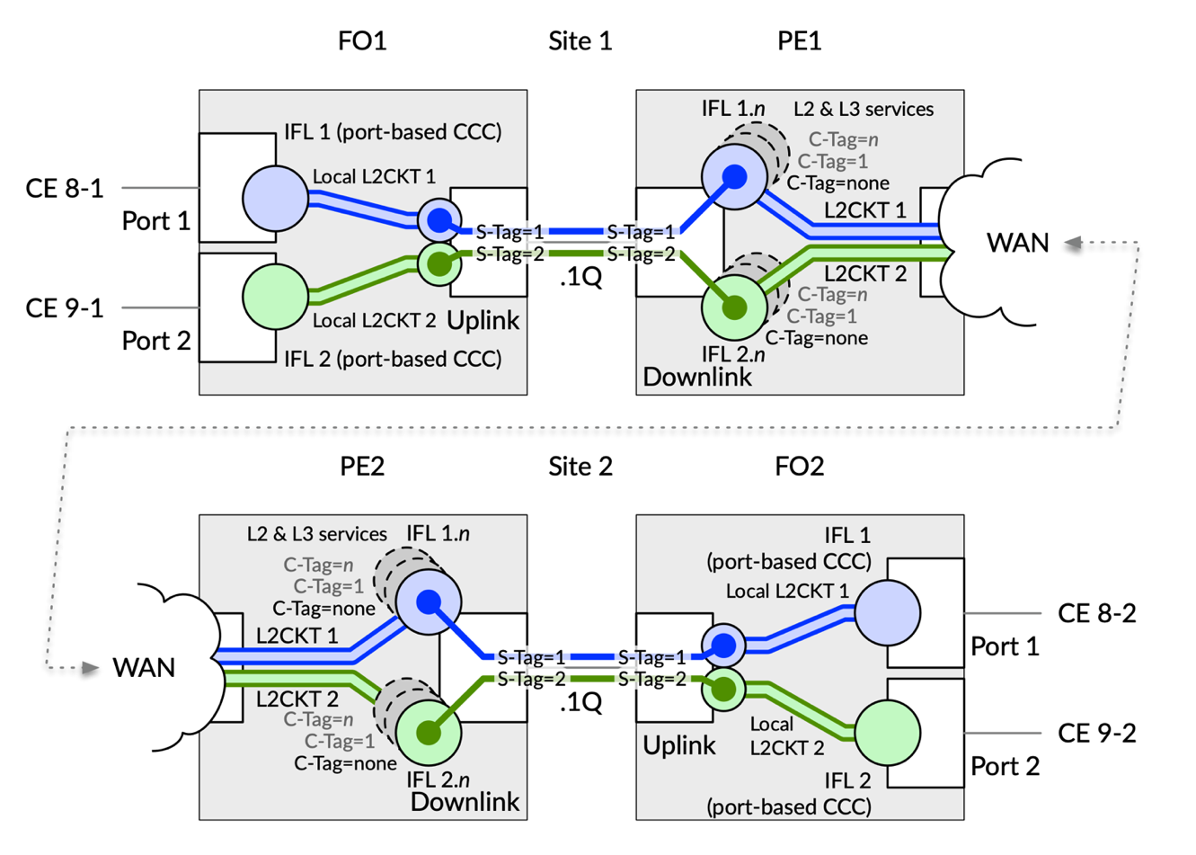
- Frames that traverse FO–PE link belong to multiple customers. 802.1Q VLAN tagging is used on the FO–PE link as a link-level virtualization technique. Think of them as S-TAGs. The fan-out device employs VLAN manipulation to push a multiplexing outer VLAN tag onto a customer's frame on egress towards the PE and pops the multiplexing outer VLAN tag from a customer's frame on ingress from the PE.
- The PE's IFLs pop the multiplexing outer VLAN tag from a customer's frame on ingress from the fan-out device and push a multiplexing outer VLAN tag onto a customer's frame on egress towards a fan-out device. An existing customer's PE IFL configuration needs to be adjusted to account for multiplexing outer VLAN tag on the FO–PE link. Note that Juniper's devices can process up to two outermost VLAN tags when deciding which IFL should accept a frame.
- Services on PE's IFLs are orthogonal to port fan-out and can be any point-to-point or multipoint L2 and/or Layer 3 (L3) services. PE's IFL is a demarcation line between fan-out domain and the rest of the provider's network, and multiplexing VLAN tag glues them together in a continuous end-to-end data plane.
Port Mapping and Traffic Multiplexing
On the fan-out device, the customer’s L2 frame information is preserved. The frame's original VLAN tags are not manipulated (although this is possible if needed through the CLI). The fan-out device is indifferent (agnostic) of the L2 and L3 technology headers of traffic that needs to be transported between CE and PE, and services provided by the PE.
The fan-out device pushes a VLAN tag onto the customer frame which might be untagged, single- tagged, or multiple-tagged on ingress to the fan-out device from the CE. It is common to refer to the outer and inner tags as Service VLAN (S-VLAN) and Customer VLAN (C-VLAN) tags respectively. On the FO–PE link, the S-VLAN identifies one CE device. This is the only VLAN tag that the fan-out device cares about, and S-VLAN tag acts as a pure locally significant multiplexing field on FO–PE link. The fan-out device is just a transparent cross-connect between an attachment circuit and PE interface. The C-VLAN identifies one customer service such as a circuit on the PE.
This is achieved by the following configuration on the fan-out device:
- The CE-facing interface is configured to use port-based mode for cross-connect local L2 circuit. See configuration in Example 1.
- The PE-facing interface is configured to use VLAN-tagged mode. Because the FO–PE link carries traffic of multiple customers. We need to somehow multiplex them. This is also known as link virtualization. There are several alternatives that allow virtualization of a point-to-point link: GRE or VXLAN tunneling, VPWS, or tagging with VLAN tags or MPLS labels. VLAN tagging is the simplest and easiest of them all and doesn't require a dedicated control channel between the ends of the link. For this reason, the port fan-out solution uses VLAN tagging as a FO–PE link virtualization method.
- Local cross-connects (think local pseudowire, which are internally in the device) transparently bridge Ethernet frames between pairs of interfaces, CE‑facing and PE‑facing, as shown in Example 3 . There is no MAC address learning during this process.
Note that the fan-out device doesn't perform local switching between CE‑facing ports. Thus, CE to CE communication always takes place through a PE device, similarly to what it was when the CE and PE were directly connected.
Example 1: Fan-Out Device—Customer Facing Interface (CE–FO link)
interfaces {
    /* Facing CUSTOMER 81 */
    et-0/0/10 {
        encapsulation ethernet-ccc;
        unit 0;
    }
    /* Facing CUSTOMER 91 */
    et-0/0/12 {
        encapsulation ethernet-ccc;
        unit 0;
    }
}
Example 2: Fan-Out device—Network Facing Interface (FO–PE link)
interfaces {
    /* Facing PE – AE member link */
    et-0/0/17 {
        ether-options {
            802.3ad ae1;
        }
    }
    /* Facing PE */
    ae1 {
        flexible-vlan-tagging;
        encapsulation flexible-ethernet-services;
        aggregated-ether-options {
            minimum-links 1;
            /* Inactive because of PR 1713849 */
            inactive: lacp {
                active;
                periodic fast;
            }
        }
        unit 1 {
            encapsulation vlan-ccc;
            vlan-id 81;
            input-vlan-map pop;
            output-vlan-map push;
        }
        unit 2 {
            encapsulation vlan-ccc;
            vlan-id 91;
            input-vlan-map pop;
            output-vlan-map push;
}}}
Example 3: Fan-Out device—Local Cross-Connect Between Customer and Network-Facing Interfaces
protocols {
    l2circuit {
        local-switching {
            /* CUSTOMER 81 - CE-facing to PE-facing cross-connect */
            interface et-0/0/10.0 {
                end-interface {
                    interface ae1.1;
                }
            }
            /* CUSTOMER 91 - CE-facing to PE-facing cross-connect */
            interface et-0/0/12.0 {
                end-interface {
                    interface ae1.2;
                }
            }
}}}
Firstly, on a PE device, we need to configure customer facing IFLs to accept customer frames. As soon as an IFL accepts a frame, the PE processes it in accordance with the services configured on that IFL. This essentially makes PE’s IFL a demarcation line between the fan-out domain and the rest of the network with its services. As a result, the port fan-out compartment is completely agnostic of services provided on a PE or in the network in general.
Recall that on the FO–PE link, the outer VLAN tag (S-TAG from the PE's perspective) is used as a locally significant multiplexing field and an outer tag's VLAN ID identifies one CE device. The outer tag protocol ID (TPID) is by default set to 0x8100 by the fan-out and PE devices, and there isn’t a need to change this default behavior. The inner tag (C‑TAG from the PE's perspective, with its C‑VLAN and C‑TPID) identifies one customer service on the PE.
Each IFL is configured with either a vlan-id <S-VLAN> or vlan-tags outer <S-VLAN> inner <options>.
Example 4 illustrates how the IFL demultiplexes and accepts frames before they are sent to respective services for further processing:
- All traffic with S‑TAG = 81 and any C‑TAG (including no C‑TAG, or an arbitrary long stack of tags) belongs to Customer 81.
- The IFL ae0.8101 accepts frames with S-TAG = 81 and C-TAG = 2001. Note that on a CE–FO link these frames are single‑tagged with VLAN ID = 2001.
- The IFL ae0.8102 accepts frames with S-TAG = 81 and C-TAG = 2002.
- The IFL ae0.8103 accepts frames with S-TAG = 81 and C-TAG = 2003.
- The IFL ae0.8198 illustrates L2 service configuration with the inner-range option; it accepts frames with S-TAG = 81 and C–TPID.TAG of 0x88a8.666–667.
- The IFL ae0.8199 illustrates L2 service configuration. This time with the inner-list option; it accepts frames with S-TAG = 81 and C-TAGs of 1–665, 668–2000, 2010–4094.
- The IFL ae.8100 accepts frames with S-TAG = 81 and either no C-TAG at all or a C-TAG that did not match any other IFL with the same S-TAG. Some people find this to be quite unexpected.
The VLAN manipulation input-vlan-map pop and the output-vlan-map push is what pushes an outer locally significant multiplexing S-TAG to customer's frame on egress towards the fan-out device and pops it on ingress from the fan-out device.
The FO-PE link in the Example 4 is an aggregated Ethernet bundle configured in static mode to match fan-out device's configuration in the Example 2.
Example 4: PE Device—Fan-Out Facing Interface (FO–PE link), with Dummy IFLs for Ingress Admission Control
interfaces {
    /* Facing FO – AE member link */
    xe-0/0/1:0 {
        gigether-options {
            802.3ad ae0;
        }
    }
    ae0 {
        /* Facing FO */
        flexible-vlan-tagging;
        encapsulation flexible-ethernet-services;
        aggregated-ether-options {
            minimum-links 1;
            /* Deactivated as a temporary workaround for PR 1713849 */
            inactive: lacp {
                active;
                periodic fast;
            }
            ethernet-switch-profile {
                tag-protocol-id [ 0x8100 0x88a8 ];
            }
        }
        /* Facing CUSTOMER 81 via FAN-OUT: CE-untagged or priority-tagged service + non-explicit VIDs */
        unit 8100 {
            encapsulation vlan-ccc;
            vlan-id 81;
            input-vlan-map pop;
            output-vlan-map push;
        }
        /* Facing CUSTOMER 81 via FAN-OUT: CE-single-tagged service 1 (L2) */
        unit 8101 {
            encapsulation vlan-ccc;
            vlan-tags outer 81 inner 2001;
            input-vlan-map pop;
            output-vlan-map push;
        }
        /* Facing CUSTOMER 81 via FAN-OUT: CE-single-tagged service 2 (L2) */
        unit 8102 {
            encapsulation vlan-ccc;
            vlan-tags outer 81 inner 2002;
            input-vlan-map pop;
            output-vlan-map push;
        }
        /* Facing CUSTOMER 81 via FAN-OUT: CE-single-tagged service 3 (L3) */
        unit 8103 {
            vlan-tags outer 81 inner 2003;
            /* Vlan-maps are not needed on L3 IFLs  */
            family inet {
                address 169.254.81.254/24;
            }
            family inet6 {
                address 2001:db8:169:254:81::fffe/112;
            }
        }
        /* Facing CUSTOMER 81 via FAN-OUT: CE-single-tagged service - Etype/VID example */
        unit 8198 {
            encapsulation vlan-ccc;
            /* vlan-tags valid only with ccc/vpls/bridge encapsulation */
            vlan-tags outer 0x8100.81 inner-range 0x88a8.666-667;
        }
        /* Facing CUSTOMER 81 via FAN-OUT: CE-single-tagged service - VID list example */
        unit 8199 {
            encapsulation vlan-ccc;
            vlan-tags outer 81 inner-list [ 1-665 668-2000 2010-4094 ];
        }
        /* Rinse and repeat for other customers; mind the outer VLAN tag */
    }
}
For a detailed configuration guide, contact your Juniper Networks representative.
Fault Detection and Propagation
Fault detection and propagation is one of the differentiating components of the solution. Fault propagation is implemented in segmented fashion: CE-FO, FO-PE, PE-PE. That is, there is no FO-to-FO CFM MA over the top of the network. The CFM MA is the connectivity fault management maintenance association. When implementing fault detection and propagation, remember the following:
- The Propagation method is a local matter on each segment.
- The CE-FO segment uses the fan-out device local cross-connect ability to drive IFL/IFD state (logically down or laser off) alone, or in combination with the CFM maintenance association end point (MEP).
- The FO–PE segment uses the CFM MEP's Interface Status TLV and/or adjacency events, depending on direction of propagating fault.
- The PE-PE segment is independent of and unrelated to the port fan-out solution. We suggest that you use the underlying network's fault detection and propagation signaling such as the status TLV in the LDP-signaled L2 circuit, BFD, and so on.
- In case of point-to-multipoint connectivity between PE IFLs, consider using end-to-end CFM MA between FO's CE‑facing ports.
With the introduction of a fan-out device, there is no longer L1 continuity between the CE and PE which impacts the link state propagation between the CE‑facing and PE‑facing interfaces on fan-out device. The port fan‑out solution employs CFM as CFM (IEEE 802.1g, ITU‑T G.8013 / Y.1731) offers the necessary capabilities to operate and maintain the network and service aspects of the Ethernet layer in point‑to‑point and multipoint topologies.
CFMs continuity check capability is used to detect loss of continuity between a pair of MEPs. When a MEP does not receive continuity check information from a peer MEP, in the list of its peer MEPs, within an interval of 3.5 times the continuity check transmission period, it detects loss of continuity (called loss of adjacency in Junos OS) to that peer MEP. The interval corresponds to a loss of three consecutive frames carrying continuity check information from the peer MEP.
MEPs make use of the Interface Status TLV that indicates the status of the interface on which the MEP transmitting the connectivity check message (CCM) is configured.
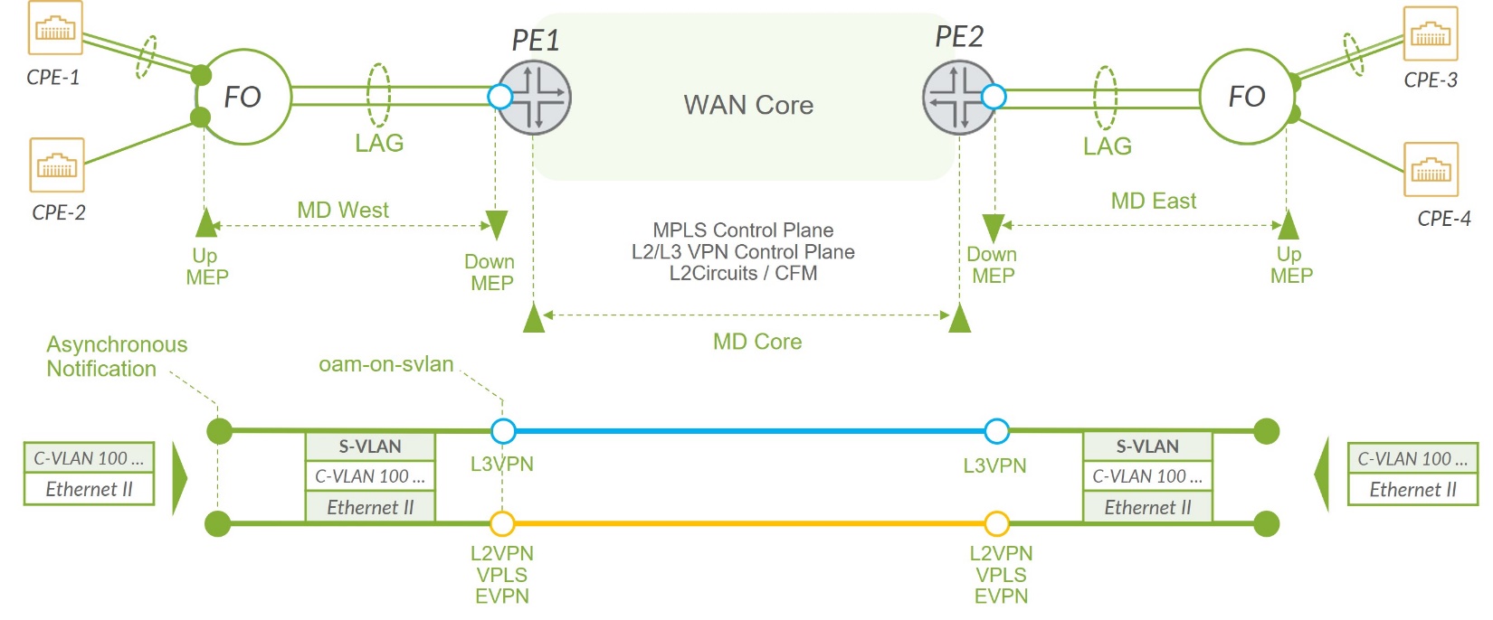
Note that the CFM session between the FO and PE pair (MD West and MD East in the Figure 2 ) are integral part of the solution. The MD Core shown in Figure 2 is agnostic to fan-out solution. The choice of a protocol used for connectivity control and state propagation between PE-nodes depends on the type of network service implemented in the network. The protocol could be the status TLV in LDP-signaled L2 circuits, IGP or MP-BGP signaling for L3VPN control plane and so on.
Eight maintenance domains (MD) in Junos OS speak, or maintenance entity groups (MEG) in ITU‑T speak levels are available to accommodate different network deployment scenarios. The ITU‑T recommends this default MD level assignment amongst customer, provider, and operator roles:
- The customer role is assigned three MD levels: 7, 6, 5
- The provider role is assigned two MD levels: 4, 3
- The operator role is assigned three MD levels: 2, 1, 0
The specific MD level assignment in the production network is a matter of mutual agreement among customer, provider and/or operator, and might differ from what we have used during our validation.
Fault detection and propagation in the port fan‑out solution adheres to modular hierarchical design principles and handles faults in a segmented and compartmentalized manner, similar to how we approached the problem of building an end‑to‑end data path in the previous section. The PE's IFLs create a demarcation line between the fan-out fault domain and the rest of the network. As a result, the port fan-out compartment is completely agnostic of faut detection and propagation methods and procedures used in the network between PEs.
Figure 2 illustrates the CFM design and end‑to‑end fault propagation in the port fan‑out solution. In a real deployment, some CEs may connect to their PEs through fan-out devices while others may not, this does not affect proposed fault propagation design nor its operation.
On the fan-out device, Up MEP is configured on the CE‑facing IFL. Up MEP actively probes connectivity through the packet forwarding engines (PFEs) on the fan-out device and its local cross-connect between CE-facing and PE-facing IFLs, on a per customer basis. If connectivity between a CE facing port on fan-out device and a PE becomes non-operational for any reason, this will be detected by the Up MEP which shuts down the laser of the CE facing port on the PO device, which in turn, signals the event to the CE. Respectively, the Down MEP configured on the S-VLAN logical interface on the PE device controls the states of corresponding customer IFL’s.
Note that in most cases the PE will have multiple CE-facing IFLs per customer (one IFL per deployed service). When the physical port on fan-out device goes down, we must assure that the failure state is accurately signaled to each service-IFL on the PE-device. To achieve that a special oam-on-svlan function is enabled on the MX PE-node to propagate the state of the S-VLAN to all logical interfaces which are configured with a given S-VLAN tag. Think of them as parent IFL and children IFLs. Parent and children IFLs in turn propagate their state throughout the rest of core network as usual, through underlying network's signaling such as a status TLV in LDP-signaled L2 circuits, route advertisement and withdrawal in the case of a L3 IFL, and so on. At the release of this JVD with Junos OS Release 23.4R2 the OAM state propagation only happens in the parent to children direction, from SVLAN to all CVLANs. State propagation in the opposite direction, from children to their parent, may be considered in future releases of Junos OS software.
This solution provides a consistent fault detection and state propagation and synchronization between physical ports of the fan-out device and mapped logical interfaces (IFL’s) of the PE-device for the following failure events:
- CE-facing on PO device is down
- FO-PE link is down
- FO to PE connectivity failure (any reason other than FO-PE link failure)
- CE facing IFL on PE device is down (driven by the Core MD control plane)
To illustrate the state propagation workflow, consider a CE-facing link failure where the CE brings its interface down or a fiber cable gets cut.
In this situation the FO's interface registers an Rx loss of line (LOL)/loss of service (LOS) event and shortly thereafter brings CE-facing IFL down. From this moment, two concurrent chains of events begin to unfold:
- The Local L2 circuit on the fan-out device propagates the fault to its PE-facing IFL, brings it down and keeps it down until the Rx LOL/LOS condition clears on CE-facing interface.
-
Concurrently, the Up MEP on the CE-facing IFL ceases to receive connectivity check messages (CCMs) from its Down MEP peer on the PE, because its underlying IFLs has been brought down in response to the Rx LOL/LOS on the physical CE-facing interface. Within an interval of 3.5 times the configured continuity check transmission period, it detects loss of continuity (adjacency-loss in Junos speak) to the peer MEP on the PE and sends a laser off command to an interface (known as an asynchronous-notification in Junos). The CE-facing interface turns its laser off.
IMPORTANT: If the CE implements the exact same logic, then even when it becomes operational again, it will have to keep its laser off in response to the LOL/LOS caused by the MEP's action. At this point, we have a deadlock and manual intervention is required to clear it. To avoid a deadlock, ensure CE does not turn its laser off in response to Rx LOL/LOS at its end.
On the PE device, the Down MEP similarly ceases to receive connectivity check messages (CCMs) from its Up MEP peer on the fan-out, because fan-out’s local cross-connect circuit brought down its respective IFL when it propagated the fault. Within an interval of 3.5 times the configured continuity check transmission period, The Down MEP detects loss of continuity (adjacency-loss in Junos OS speak) to the peer MEP on the PE and performs the action defined in its action-profile (for example, interface-down) of the parent IFL, which thanks to oam-on-svlan automagically brings down its children IFLs.
Finally, the fault propagates throughout the network to the far end PEs through respective signaling mechanisms. A parent IFL on a far end PE goes down. The Down MEP configured on this IFL originates interface status TLV = down to its peer Up MEP on the fan-out device, which then turns the laser off on the CE-facing interface. The CE registers Rx LOL/LOS faults and processes in accordance with its configuration. That completes the propagation cycle of the CE-FO failure.
For the complete configuration details for fan-out failure detection and state propagation, contact your Juniper Networks representative.
Port Fan-Out L2CP Transparency
Transparency in the data plane is relatively easy to achieve. While different switches and routers and software versions demonstrate various degrees of L2CP transparency and offer different controls to an operator, It is impractical to aim at absolute L2CP transparency because some L2CPs are designed to be locally significant between link partners on an Ethernet link. Notable examples are IEEE 802.3 Ethernet PAUSE, IEEE 802.1Qbb priority flow control (PFC), and micro-BFD.
Table 1 has a summary of L2CP and other control protocol transparency test results for the ACX702 device and the MX480 MPC10E router.
| Layer 2 and Other Control Protocol | Result |
|---|---|
| 01:00:0c:cc:cc:cc 0xaa 0xaa 0x00000c 0x2004 DTP | PASS |
| 01:00:0c:cc:cc:cd 0xaa 0xaa 0x3 0x010b PVST+ | PASS |
| 01:80:c2:00:00:00 0x42 0x42 0x3 STP | PASS |
| 01:80:c2:00:00:00 0x8809 0x01 LACP alt. DMAC (Nearest Customer Bridge) | PASS |
| 01:80:c2:00:00:00 0x888e EAPOL/MKA alt. DMAC (Nearest Customer Bridge) | PASS |
| 01:80:c2:00:00:00 0x88cc LLDP alt. DMAC (Nearest Customer Bridge) | PASS |
| 01:80:c2:00:00:01 0x8808 0x0001 802.3x PAUSE | PEER (1) |
| 01:80:c2:00:00:01 0x8808 0x0101 802.1Qbb PAUSE | PEER (1) |
| 01:80:c2:00:00:02 0x8809 0x01 LACP default DMAC (Slow Protocols) | PASS | PEER | DROP |
| 01:80:c2:00:00:02 0x8809 0x02 LAMP default DMAC (Slow Protocols) | PASS | PEER | DROP |
| 01:80:c2:00:00:02 0x8809 0x03 Link OAM | PASS |
| 01:80:c2:00:00:02 0x8809 0x0a ESMC | DROP |
| 01:80:c2:00:00:03 0x8809 0x01 LACP alt. DMAC (Nearest Non-TPMR Bridge) | PASS |
| 01:80:c2:00:00:03 0x8809 0x02 LAMP alt. DMAC (Nearest Non-TPMR Bridge) | PASS |
| 01:80:c2:00:00:03 0x888e EAPoL/MKA default DMAC (Nearest Non-TPMR Bridge) | PASS |
| 01:80:c2:00:00:03 0x88cc LLDP alt. DMAC (Nearest Non-TPMR Bridge) | PASS |
| 01:80:c2:00:00:04 802.1Q MAC-specific Ctrl Protos | PASS |
| 01:80:c2:00:00:05 802.1Q Reserved for future | PASS |
| 01:80:c2:00:00:06 802.1Q Reserved for future | PASS |
| 01:80:c2:00:00:07 0x88ee MEF E-LMI | PASS |
| 01:80:c2:00:00:08 Provider Bridge Group | PASS |
| 01:80:c2:00:00:09 802.1Q Reserved for future | PASS |
| 01:80:c2:00:00:0a 802.1Q Reserved for future | PASS |
| 01:80:c2:00:00:0b 0x888e EAPOL/MKA alt. DMAC (EDE-SS PEP Address) | PASS |
| 01:80:c2:00:00:0c 802.1Q Reserved for future | PASS |
| 01:80:c2:00:00:0d 0x88f5 Provider Bridge MVRP | PASS |
| 01:80:c2:00:00:0e 0x888e EAPOL.MKA alternate DMAC (Nearest Bridge) | PASS |
| 01:80:c2:00:00:0e 0x88cc LLDP default DMAC (Nearest Bridge) | PASS |
| 01:80:c2:00:00:0e 0x88f7 PTP | PASS |
| 01:80:c2:00:00:0f 802.1Q Reserved for future | PASS |
| 01:80:c2:00:00:1f 0x888e EAPOL/MKA alt. DMAC (EDE-CC PEP Address) | PASS |
| 01:80:c2:00:00:20-2f GARP/MRP | PASS |
| 01:80:c2:00:00:30 0x8902 CFM Level 0 | PASS or DROP (2) |
| 01:80:c2:00:00:31 0x8902 CFM Level 1 | PASS or DROP (2) |
| 01:80:c2:00:00:32 0x8902 CFM Level 2 | PASS or DROP (2) |
| 01:80:c2:00:00:33 0x8902 CFM Level 3 | PASS or DROP (2) |
| 01:80:c2:00:00:34 0x8902 CFM Level 4 | PASS or DROP (2) |
| 01:80:c2:00:00:35 0x8902 CFM Level 5 | PASS or DROP (2) |
| 01:80:c2:00:00:36 0x8902 CFM Level 6 | PASS or DROP (2) |
| 01:80:c2:00:00:37 0x8902 CFM Level 7 | PASS or DROP (2) |
| micro-BFD 01:00:5e:90:00:01 udp/6784 | DROP |
Legend:
- DROP—A frame is dropped on ingress without any further processing.
- PASS—A frame is transparently forwarded, without processing in the control plane.
- PEER—A frame is trapped on ingress and sent to control plane for local processing.
Notes in Table 1:
(1) 802.3 MAC Control frames with DMAC 01-80-C2-00-00-01 and EtherType 0x8808 are discarded in hardware as these packets are considered Rx control packets by the DNX Jericho 2 chipset of the FO deice and consumed in hardware irrespective of their subtype. Due to this hardware behavior, all types of 802.3 MAC Control frames such as Pause, Priority Flow Control, Multipoint MAC control and Organization Specific Extensions are discarded in hardware.
(2) In ITU-T G.8013/Y.1731 OAM functions and mechanisms for Ethernet based networks, OAM transparency refers to the ability to allow transparent carrying of OAM frames belonging to higher-level MEGs across other lower-level MEGs when the MEGs are nested. OAM frames belonging to an administrative domain originate and terminate in MEPs present at the boundary of that administrative domain. A MEP prevents OAM frames corresponding to a MEG in the administrative domain, from leaking outside that administrative domain. However, when a MEP is not present or is faulty, the associated OAM frames could leave the administrative domain. Similarly, a MEP present at the boundary of an administrative domain protects the administrative domain from OAM frames belonging to other administrative domains. The MEP allows OAM frames from outside administrative domains belonging to higher-level MEs to pass transparently, while it blocks OAM frames from outside administrative domains belonging to same or lower-level MEs.
QoS/CoS Considerations
CoS config is a critical part of the solution which enables the network to avoid false positive interface failure detection in congestion scenarios: FO-CE interface congestion and FO-PE interface congestion. High level design principals and solution requirements for quality of service are:
- The oversubscription of a fan-out device should be avoided or reduced to a reasonable and acceptable level
- Contention of FO—PE link must be under check
- Prevent overwhelming of a customer's attachment circuit FO➜CE
- Minimal and localized alterations to an already existing QoS architecture, design, and deployment
Class of Service Design
Oversubscription of fan-out can be eliminated by sizing fan-out device appropriately during network design. Choose a fan-out device model that has adequate forwarding capacity for aggregate bandwidth on its customer-facing interfaces plus FO-PE links. For example, forwarding ASIC in ACX7024 has throughput of 360 Gbps and 300 Mpps:
- On a fan-out device:
- Ingress from CE
- Traffic conditioning by envelope policing of transit/revenue traffic on a customer's attachment circuit. (Traffic is received or sent in regulated amounts to ensure that it fits within the acceptable or promised/agreed traffic profile for a particular set of flows. We call this traffic profile an envelope. There are many ways to define a set of flows such as per subscriber or group of subscribers, per service, logical interface, and so on. Conformance to a traffic envelope is enforced by input policing and output queueing and scheduling (incl. shaping). This limits surges that may congest a network and/or violate a service level agreement (SLA). The port fan-out solution makes use of these concepts and tools at various levels of the Hierarchical QoS architecture.
- The MEF 10.4 Subscriber Ethernet Service Attributes has the following definition: An Envelope is a set that contains one or more bandwidth profile flows that can share bandwidth resources that are represented by tokens. This avoids oversubscribing the FO-PE link in a deployment that is prone to such oversubscription because of deliberately or incorrectly sized fan-out device interfaces facing customers and the PE. Also, if there is a possibility of a customer exceeding their contractual traffic rate, ingress envelope policing can be moved from IFLs on the PE to a customer facing interface on the fan-out device, so that excess traffic never traverses FO-PE link.
- Assign your own CFM Up MEP’s PDUs to a dedicated forwarding class, with its own egress queue (think of it as a super network control class and its queue). Up MEP’s PDUs appear as they have entered fan-out device through a front panel port. They undergo exact same treatment as any other ingress packet. This is by OAM/CFM design.
- Assuming that the fan-out device and its interfaces are sized such that there is no potential for oversubscription of the FO-PE link, all transit traffic ingressing from a CE is treated as belonging to the same forwarding class and enqueued in the same egress queue on a PE facing interface.
- Egress to PE
- Separate own real-time and near-real-time control traffic from transit/revenue traffic by enqueueing them in different queues.
- Do not mix [near-]real-time (own CFM PDUs) and bulk control or management traffic.
- Optional. Increase priority of the network control queue to minimize jitter for [near-]real-time control traffic. Inconsistent arrival times of CFM continuity check messages are known to cause loss of MEP adjacency on a peer MEP at short continuity check intervals and with low loss-threshold setting.
- Ingress from PE
- Assign peer’s CFM PDUs to a dedicated forwarding class, with its own egress queue (a super network control class and its queue).
- If egress envelope shaping (envelope shaping, in Juniper terminology refers to hierarchical shaping which is available on MX Series routers) to a contractual or attachment circuit’s rate is implemented on a PE towards a customer, all transit traffic ingressing from a PE is treated as belonging to the same forwarding class and enqueued in the same egress queue on a CE‑facing interface.
- Egress to CE
- If egress envelope shaping to a contractual or attachment circuit’s rate is implemented on a PE towards a customer, all transit traffic ingressing from a PE is treated as belonging to the same forwarding class and enqueued in the same egress queue on a CE‑facing interface.
- Ingress from CE
- On a PE:
- Ingress from fan-out (and customer)
- Apply your usual traffic conditioning (for example, policing), QoS classification, filters, and so on. Ensure that while doing so you are not inadvertently punishing incoming peer’s CFM PDUs.
- Egress to network
- Apply your usual scheduling and queueing, ToS re-write, and so on.
- Ingress from network
- Classify ingressing control and management traffic into a traffic class other than default network-control class. This is to avoid mixing transit control and management traffic with own CFM Down MEP’s PDUs that are sensitive to jitter and loss and are enqueued in the default network-control queue (explained why later in this section).
- Egress to fan-out (and customer)
- Envelope shaping to the attachment circuit’s rate or a contractual rate, whichever is lower.
- Increase priority of the default network-control queue to minimize jitter for [near-]real-time control traffic. Recall that transit control ad management traffic has been classified in a different class on ingress from the network. Inconsistent arrival times of CFM continuity check messages are known to cause loss of MEP adjacency on a peer MEP at short continuity check intervals and with low loss-threshold setting.
- Self-originated (a.k.a. host-outbound, locally originated, or RE traffic) is being
treated in a default manner.
- For a complete list of self-originated control and management protocols and their queue assignment on Juniper’s routers and switches, see: https://www.juniper.net/documentation/us/en/software/junos/cos/topics/example/cos-host-outbound-traffic-default-classification-and-dscp-remarking.html
- Ingress from fan-out (and customer)