ON THIS PAGE
Solution Architecture
The solutions provide for the integration of traditional Metro ring architectures with multi-instance ISIS, Flex-Algo Prefix Metric (FAPM) into Segment Routing MPLS with Metro fabrics leveraging inter-domain Transport Classes and Inter-AS BGP Classful Transport with end-to-end multi-domain service mapping.
The solution infrastructure can be divided into two major segments: Metro fabric and Metro multi-ring topologies. The end-to-end topology makes use of SR-MPLS and Flex-Algo. The following sections describe the components, which are common across both architectures.
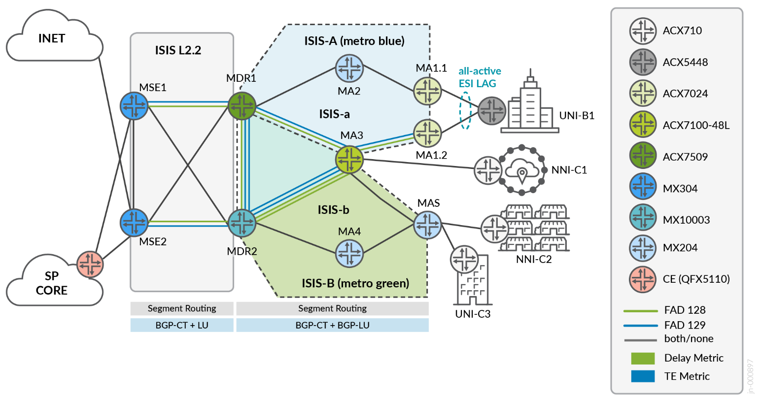
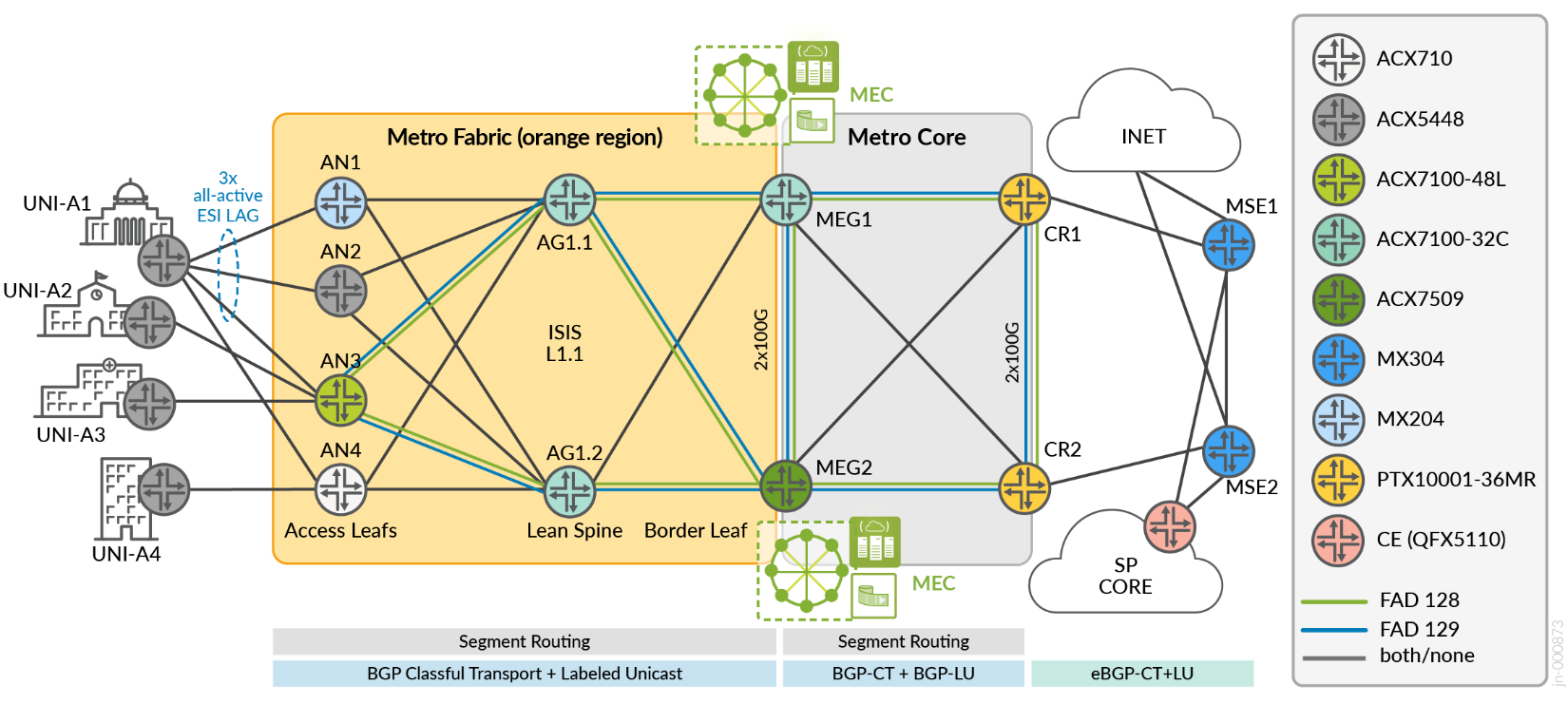
Flex Algo 128 include-any GREEN delay-metric
Flex Algo 129 include-any BLUE TE-metric
Transport Class 4000 maps to GOLD
Transport Class 6000 maps to BRONZE
| Topology Definitions | Role | Device |
|---|---|---|
| Access Leaf | AN | ACX7100-48L (DUT), ACX710, ACX5448, MX204 |
| Lean Spine | AG1 | ACX7100-32C |
| Lean Edge Border Leaf | MEG | Metro Edge Gateway: ACX7509 (DUT), ACX7100-32C (DUT) |
| Core | CR | PTX10001-36MR |
| Multiservices Edge | MSE | MX304 (DUT) |
| Metro Distribution Router | MDR | MX10003, ACX7509 (DUT) |
| Metro Access Node | MA | ACX7024 (DUT), ACX7100-48L (DUT), MX204 |
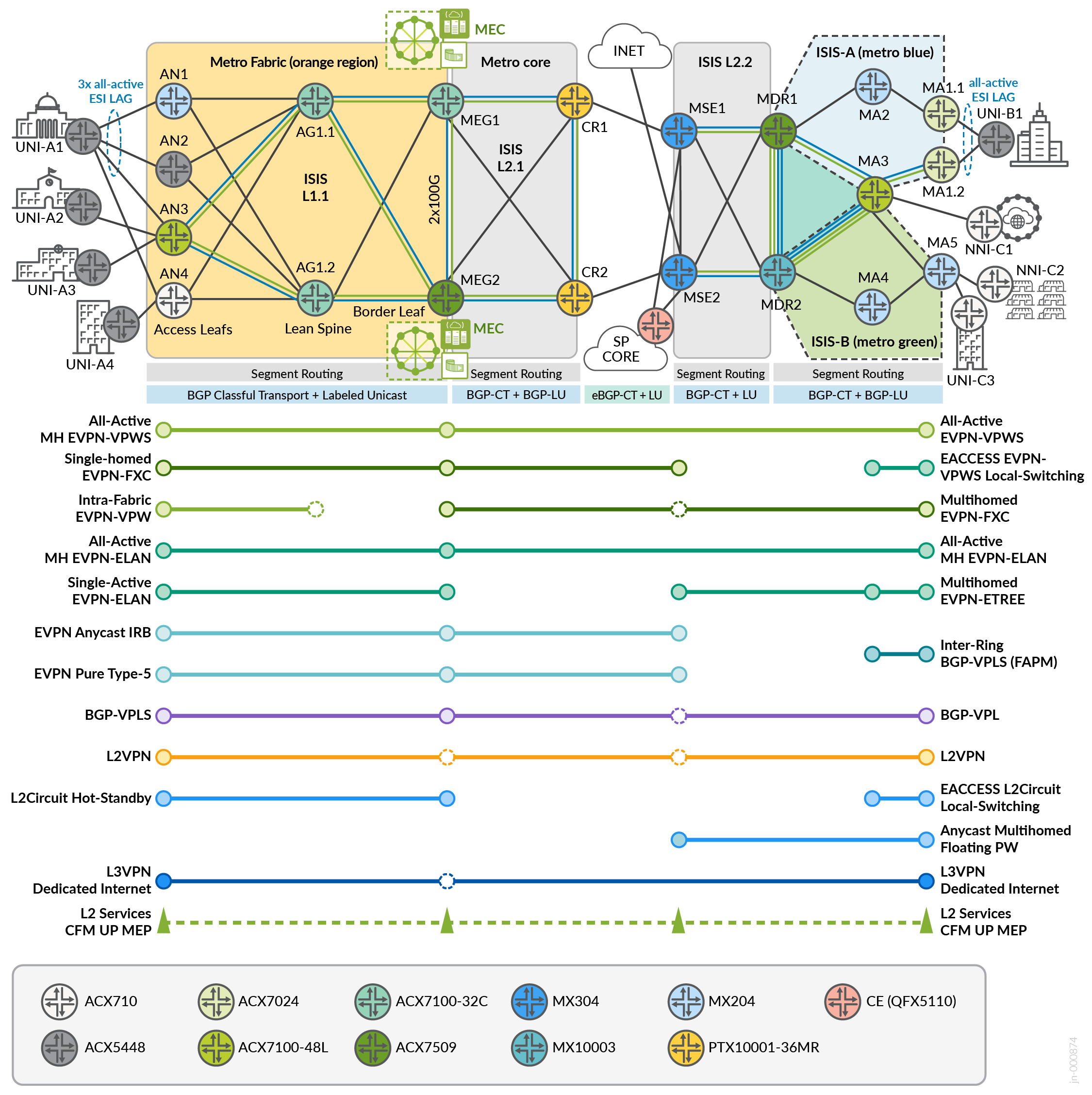
Solutions for E-Line/E-LAN/E-ACCESS Metro Services based on next-generation Seamless Segment Routing transport infrastructure, incorporating ACX7024, ACX7100-48L, and MX204 as access nodes; ACX7100-32C and ACX7509 platforms as Lean Edge solution offering connectivity options into Cloud Compute complexes; and MX304 Multiservices Edge (MSE) supporting complex services, termination, and interconnectivity with other network segments or Internet peering.
Connectivity options for port-based (EPL) and VLAN-based (EVPL) IEEE 802.1q/QinQ-based EVCs to support end-to-end active-active highly available services including EVPN-VPWS/FXC/EVPN-ELAN and coexisting with traditional VPN services including multi-site VPLS, Hot-Standby L2Circuit, L2VPN, and L3VPN with Internet Access. Legacy static PWs are migrated to an Anycast Floating PW solution leveraging Anycast-SID for L2 Q-in-Q connectivity. Most Layer 2 services include E-OAM performance monitoring.
Underlay Attributes
The common underlay included is Segment Routing MPLS with Labeled ISIS. TI-LFA is the protection mechanism of choice with loose mode, which allows the transition to link-protection should node-protection become unavailable.
Characteristics of the SR-MPLS design include:
- ISIS (L1 or L2) enabled for all devices.
- BFD over L-ISIS links.
- Additional ISIS tuning involves the following attributes but should be appropriately
set for the network deployment to ensure stability:
- Improve ISIS link state PDU interval to 10ms (100ms default),
- ISIS maximum hello size is increased to 9106 based on interface ISO MTU configuration, which can help identify MTU issues.
- SPF options are tuned within a range to prevent network instability.
- Consistent SRGB label range between 16000 and 24000. In earlier Junos OS implementations, SRGB is configured under the IGP hierarchy. This is still supported. Now SRGB is configured conveniently under the MPLS configuration hierarchy and is consistent with other label range configurations.
- TI-LFA provides both link and node protection with a configured maximum-label of 3 for backup paths.
- Microloop Avoidance is enabled for all devices.
ISIS is the IGP that is used for the solution architecture. The JVD includes three IGP metric combinations using Application Specific Link Attributes (ASLA) link affinity constraints for computed paths:
- IGP Metrics for uncolored paths (BGP-LU), referenced as best effort.
- TE Metrics for Transport Class Bronze (BGP-CT).
- Static Delay Metrics for Transport Class Gold (BGP-CT).
Flexible Algorithm
Flexible Algorithm was ratified by RFC9350 and enables controllerless lightweight traffic engineering solutions, while supporting advanced protection mechanisms, like TI-LFA. TLV advertisements describe the key attributes of calculation-type, metric-type, priority, and set of link constraints used for IGP-computed best paths. The coalescence of these values defines the Flexible Algorithm Definition (FAD).
Segment Routing prefix-SIDs are then associated with the Flex-Algo identifier, thereby representing the computed path across participating nodes. By leveraging different constraints and metric types, multiple layers of abstraction can be created by forming colored paths through the network.
In the JVD, all nodes will participate in flex-algo and therefore must advertise the SR-Algorithm sub-TLV node capability. The FAD sub-TLV announcements are not required by every router. As a best practice to avoid conflict resolution, FAD announcements in the JVD are restrained to only the border nodes (ABR/ASBR). Both ABRs should be configured to advertise the FADs. Both sub-TLVs have level scope and therefore are not advertised across IGP boundaries without an additional mechanism for sharing inter-region attributes, explained further on.
After several draft revisions, the flex-algo RFC was finalized in 2023. But the lead-up created a landscape of shifting standards, particularly around link affinity attributes where three permutations emerged with legacy (RFC5305 section 3.1), Common ASLA (RFC8919 section 6.3.1), and finally Flex-Algo ASLA (RFC9350).
In Metro EBS JVD, the flex-algo implementation includes the latest link attribute definitions specified in RFC9350 for the use of Application-specific link attributes. The link attributes, as defined in RFC8919 for ISIS (or RFC8920 for OSPF), include TE-metric, admin-group, and link-delay. Junos OS/Junos OS Evolved supports L-Flag, allowing backward compatibility with legacy attributes and default behavior allows fallback from Flex-Algo ASLA to Common ASLA and finally to legacy TE attributes. In the JVD, legacy advertisements are disabled with strict-sla-based-flex-algorithm knob but not a requirement for the solution.
A final consideration is IGP scale as each Flex-Algo will compute its own path. In the JVD, we define three paths with two algos, gold (128) using delay metrics, bronze (129) with TE metrics, and best effort (inet.3) with IGP metrics.
Transport Classes
Transport classes define a set of common constraint attributes that are used to create transport tunnels. Transport classes can be associated with different underlay protocols, like RSVP or SR-TE. In the JVD, the transport classes will use ISIS Flex-Algo to create multiple layers of network abstraction over the same physical infrastructure. Services are then mapped to the color transport, enabling a simplistic method for intelligent traffic steering.
With the latest implementations of classful transport, services that are mapped onto transport class tunnels can be configured to transition or fallback between tunnel hierarchies as required. The resolution scheme attribute governs the next-hop resolution tables to consider.
Two styles of resolution scheme fallback methodologies are included in the JVD:
- No Fallback—This method ensures that traffic is mapped to the appropriate color. If not, traffic is discarded.
- Cascade—This is the preferred solution validated because it enables fallback for gold paths to bronze, and bronze paths to Inet.3 (best effort).
BGP Routing Policy
BGP routing policies tag all routes based on the originating network segment to enable targeted redistribution, prevent loops, and simplify troubleshooting. To prevent loops, border nodes of each region only export routes that match the local region community and reject routes matching the peer region communities. For improved failure detection, BFD is configured on all BGP sessions using a 300ms detection timer. BFD timers should be tuned based on network performance, stability, and device capabilities.
BGP best practices are applied where relevant and include the following:
- BGP path-selection external-router-id modifies the path selection algorithm to always use router-ID for deciding the active path between EBGP paths, which helps with more consistent BGP behavior.
- BGP hold-time (default 90 seconds) is reduced to 10 seconds.
- When BGP hold-time is less than 20 seconds, precision-timers should be configured since it creates an increased workload on the routing engine CPU. Precision timers enable a dedicated kernel thread for BGP computation to ensure keepalives survive even with scheduler slips. This helps to prevent BGP session flaps because of the expiration of hold-time.
- With bgp-error-tolerance, additional default error handling mechanisms are enabled, including limiting malformed hidden routes stored in memory to 1000 and suppressing logging of malformed BGP update messages for 300 seconds.
- The BGP maximum segment size tcp-mss is increased from default 500 bytes to the maximum of 4096 bytes to help accelerate convergence.
PE link protection is enabled for EBGP-LU and BGP-CT paths in addition to per-prefix-label to improve convergence. This can be a topic of scaling concern, but for transport-only segments, the route scale is usually manageable. Only labeled-unicast is configured with per-prefix-label since BGP-CT transport family enables this behavior by default.
BGP Route Reflectors
Fabric and multi-ring regions should use redundant BGP route reflectors for access node clients. To optimize intra-fabric and inter-ring communication between access nodes in the same region, multi-protocol BGP for VPN families will not include the next-hop self option. Unique cluster IDs are used to maximize convergence. As a general practice for local reachability within the fabric, access segment loopback addresses are reachable only by ISIS and are not leaked into BGP. Only remote loopbacks should be learned by BGP.
BGP route reflectors will enable the multiprotocol families:
- labeled-unicast (BGP-LU)
- transport (BGP-CT)
- inet-vpn (L3VPN)
- inet6-vpn (6vPE)
- l2vpn signaling (L2VPN, VPLS)
- evpn signaling (EVPN)
- route-target (RTF)
In all places where Route Target Constraint (RTC) is configured, the additional next-hop-resolution no-resolution configuration option is included for bypassing next hop resolution for RIB installation. This configuration is useful for routes that are not used for forwarding, like non-forwarding RRs. The JVD route reflectors are in the forwarding path, but RTF is strictly a control-plane element. To further optimize the topology, the advertise-default option can be used to send only a default route target to PE clients. The logical use would be in supporting the featured access segments.
Metro Fabric and Metro Multi-Ring segments deploy different route reflector strategies. In the fabric, the Metro edge gateways (MEG) function as the access node (AN) reflectors for both transport and services routes (BGP-LU, BGP-CT, and MP-BGP). In the multi-ring segment, the metro access nodes (MA) peer as route reflector clients with the metro distribution routers (MDR), which are only transport reflectors (BGP-LU, BGP-CT). All services (MP-BGP) leverage the multiservices edge (MSE) route reflectors.
Metro Ring Architecture
The following sections describe the proposed metro ring architectures. The design comprises a multi-ring topology with multi-instance ISIS and inherits the common elements described earlier.
Key Metro Ring Features
- Multi-Instance ISIS (blue and green rings).
- Flex-Algo Prefix Metrics (FAPM) leaking across multiple ISIS instances to optimize inter-ring forwarding.
- Intra-domain Transport Class Service Mapping.
- EVPN Floating PW with Anycast-SID (migrating from legacy L2CKT).
- EVPN-ETREE, EVPN-FXC, EVPN-VPWS, EVPN-ELAN
- L2Circuit, L2VPN, and BGP-VPLS.
- Local Switching (LSW) EVPN-VPWS and L2Circuit
- L3VPN Internet services
The primary common BGP communities originating from metro ring regions include:
- CM-LOOPBACK (63536:10000)
- CM-SERVICE-EDGE (63536:10)
- CM-METRO-RING (63536:20)
- CM-REGION-EDGE (63536:30)
- CM-TC-4000-GOLD (transport-target:0:4000)
- CM-TC-6000-BRONZE (transport-target:0:6000)
- CM-INET-DEFAULT (target:63536:11111)
- CM-L3VPN-PUB (target:63536:22222)
Multi-Instance ISIS
Both blue and green rings are functionally identical as Level 2 ISIS instances. Most devices operate using a single ISIS instance that is configured under the normal global hierarchy. Devices that attach to multiple IGP regions are configured with multiple ISIS instances. This includes MDR1, MDR2, and MA3. Links between MDR1 and MDR2 share a common LAG, split logically by VLANs between global, metro-a, and metro-b ISIS instances. The interfaces between MDR1 and MDR2 toward MA3 are also logically divided by VLANs across a common physical interface. All other links are domain-specific and exist in only a single IGP instance.
There is no requirement to share common interfaces in this architecture. The JVD demonstrates how these challenging connectivity scenarios can be achieved, creating definitive postures for route leaking at the border demarcation points.
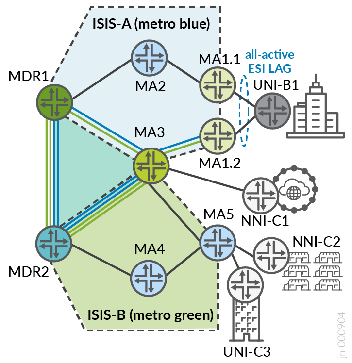
All inter-instance route leaking between rings is done at the MDR1 and MDR2 nodes. The logic for leaking only at MDRs rather than MA3 can be attributed to anticipating network expansion with additional rings, causing MA3 to become a less preferred leaking point. The MDR presents the ideal demarcation point with visibility of all rings for the regions. Routes leaked between ISIS instances are tagged to prevent loops. The MDRs function as the BGP transport route reflectors (BGP-LU and BGP-CT) for all ring access nodes (no multi-protocol BGP). For VPN services, access nodes peer using MP-BGP with MSE route reflectors.
Leaking between global ISIS area ID 005 into ISIS instances metro-a (001) and metro-b (002) is restricted to only BGP. At this juncture, seamless SR-MPLS with BGP-LU and BGP-CT is leveraged. The solution could instead leak between the IGP domains that are part of the common autonomous system, but here the solution provides the ability to divide the IGP into smaller domains and reduce the blast radius.
The same system ID is used for all ISIS instances and unique AREA IDs are included as follows:
- 0005–Global Instance
- 0001–Metro-A Instance
- 0002–Metro-B Instance
The IP scheme proposes aggregate tags to enable easier route redistribution and loop prevention as follows:
- 10.10.0.0/24–TAG2 5: GLOBAL
- 10.10.1.0/24–TAG2 1: METRO-A
- 10.10.2.0/24–TAG2 2: METRO-B
Inter-Ring Flex-Algo Prefix Leaking
Flex-Algo inter-domain procedures are explained in RFC9350 section 13.1. Flex-Algo Prefix Metric (FAPM) is a sub-TLV advertisement that carries a prefix association. Flex-Algo with Application Specific Link Attributes (ASLA) metrics are defined on all nodes, with Flex-Algo Definitions (FADs) advertised only by MDR border nodes. Application Specific Link Attributes is the latest and standardized version for Flex-Algo Metric advertisement. Flex-Algo Prefix Metric (FAPM) leaking is performed between rings through MDRs to enable inter-ring traffic flows and are optimized within the region.
MSE1 and MSE2 function as redundant route reflectors for all ring nodes and additionally support inter-AS functionalities enhanced with BGP-LU and BGP-CT. To ensure traffic flows are optimized within and between rings, VPN services (MP-BGP) will not leverage next-hop self at the MSE. For LU/CT transport routes, next-hop self is mandatory to facilitate inter-AS reachability.
SR-MPLS is the underlay of choice using Flex-Algo with ASLA metrics and transport classes defining green and blue paths through the network. Green paths utilize ISIS delay metrics and blue paths use TE metrics. The IGP metrics are used for color-agnostic paths, which could be extended to consider colored or non-colored paths. All routes leaked between domains are given a common ISIS tag and any routes that are exported that already include this tag are rejected to prevent loops.
Intra-AS BGP Classful Transport and Labeled Unicast
There are several viable strategies for communications across IGP domains within the same autonomous system. In the JVD we provide a few variations using FAPM to leak prefixes between ISIS instances where each instance denotes a metro ring entity. From the collective multi-instance ISIS domains toward the global ISIS domain (existing between MDR and MSE segments), we decide to prohibit any IGP leaking and only use BGP-LU and BGP-CT as the inter-domain stitching mechanisms. This ensures the IGP blast radius is contained within the specific areas.
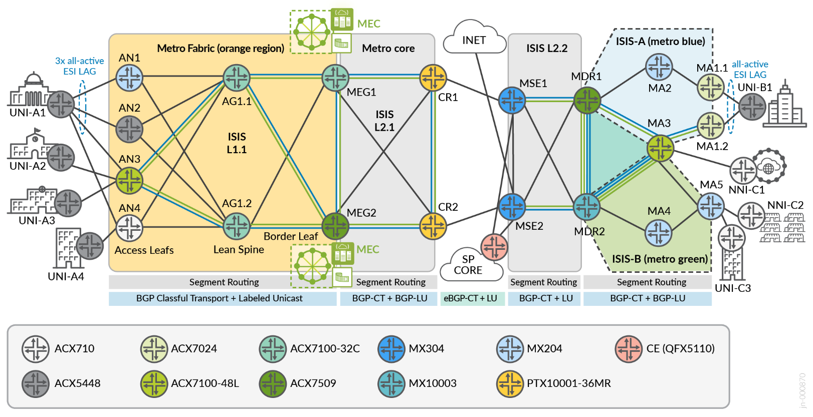
Metro Fabric Architecture
IP Fabrics are well understood and heavily deployed by hyper-scalers to deliver the promise of high bandwidth, resiliency, and virtually unlimited scale-out capability. Metro Fabrics have been a common point of discussion but generally lack clear definitions. The infrastructure placement becomes a key consideration. While IP Fabrics are commonly built within a data center environment, practically nullifying associated fiber transport costs, the metro typically spans greater distances between physical collocations, which can lead to more expensive optics. Thus, implementing a metro fabric can vary between service providers and is determined by the associated transport costs.
The model proposed by the Metro EBS JVD considers an infrastructure built with the flexibility to support cost-effective scale-out solutions that are contained within a single physical location and/or supporting spine-and-leaf metro access node locations. In the general sense, we deploy a two-stage fabric using MPLS as the underlay transport of choice.
In the topology, the metro fabric refers to the orange region. The metro core is the grey region.
Key Metro Fabric Features
- Lean edge services aggregation
- Metro edge gateway with multiaccess edge compute interconnectivity
- Optimized forwarding paths over 2-stage MPLS fabric
- EVPN-FXC (aware + unaware), EVPN-VPWS, EVPN-ELAN
- L2Circuit, L2VPN, BGP-VPLS
- Dedicated Internet Access (DIA): L3VPN, EVPN Type-5, EVPN IRB VGA
- All-Active ESI LAG load-shared across three PEs
- Active-active and hot-standby services
- Logical Interface policers
To optimize VPN flows within the Metro Fabric, a pair of route reflectors (hosted by border leaf nodes MEG1/MEG2) are used. While they operate in the forwarding path, we must avoid setting next-hop to self for the multi-protocol BGP fabric services to enable intra-fabric traffic to stay within the spine. Lean spine nodes (AG1.1, AG1.2) are BGP-free with only SR-MPLS configuration. The IGP domain comprises ISIS Level 1 in the metro fabric access network and Level 2 in the metro core. All the metro fabric infrastructure implements the same area ID:
- 0000–Global Instance
Traffic leaking between L1 and L2 ISIS can be accommodated with IGP machinery and Flex Algo prefix leaking using Flex-Algo Prefix Metric (FAPM) or IGP leaking explicitly restricted and relying only on BGP as the inter-domain protocol of choice.
The Flexible Algorithm Definitions (FADs) are only advertised from the border nodes at MEG1 and MEG2 positions. Similar to the Metro Ring design, only two transport classes are created: Gold and Bronze. Resolution schemes enable gold services to cascade failover onto bronze paths if a gold path is unavailable and bronze is enabled to failover to “best effort” uncolored paths (inet.3). The default behavior if no custom resolution scheme is configured, would be to enable all transport classes to failover onto uncolored paths, resolving from the inet.3 table.
Similar to the metro ring design, we use BGP community-based routing to control how routes are imported and exported across the various domains. The primary common BGP communities originating from metro fabric regions include:
- CM-LOOPBACK (63535:10000)
- CM-METRO-FABRIC (63535:1)
- CM-ACCESS-FABRIC (63535:2)
- CM-REGIONAL-BORDER (63535:3)
- CM-TC-4000-GOLD (transport-target:0:4000)
- CM-TC-6000-BRONZE (transport-target:0:6000)
- CM-INET-DEFAULT (target:63536:11111)
- CM-L3VPN-PUB (target:63536:22222)
The core-facing interface IP scheme is delegated with an aggregate tag:
- 10.10.0.0/24 – TAG2 10: GLOBAL
Overlay Attributes
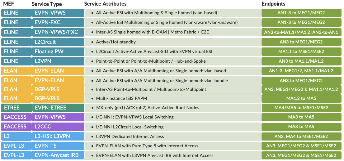
The following sections describe the implementation and use cases of services that are included in the Metro Ethernet Business Services JVD. This includes the termination points and how these services relate to MEF definitions. However, it is important to note that MEF alignment is not a requirement to use any of the described services. Multiple permutations are included to cover different customer use cases, but many more options are possible and supported.
Metro EBS Service Delivery Models
Over twenty use cases are covered for delivering Metro Ethernet services. Traditional Layer 2 VPN services are included along with L2Circuit with hot-standby, L2VPN, and VPLS. This shows the ability to coexist with newer EVPN-VPWS, EVPN-FXC, EVPN-ELAN, and EVPN-ETREE services over common modern Metro ring and fabric infrastructures. In addition, the Floating PW solution delivers a massive upgrade to legacy static L2Circuit by leveraging Anycast-SID with all-active virtual ESI (vESI) for active-active multi-homing. Layer 3 services are supported using traditional L3VPN, EVPN-ELAN Type 5, and EVPN IRB Virtual Gateway Address (VGA) models. High-availability services are included, like active-active EVPN and hot standby L2CKT.
Service interconnection models are considered for specific segments around lean edge for Metro edge compute handoff where multiple options exist like EVPN-VXLAN or SRv6 for IP Fabric interworking, however for this initial phase, we selected a Q-in-Q handoff, which enables services to be connected into the edge complex resources based on inner and or outer tag match. Operators are free to perform VLAN manipulation to meet this goal. Similar considerations are made for multiservices edge connectivity to facilitate Internet services or SP core for Layer 2 connectivity into additional network segments. Previous 5G Metro JVDs covered over 80 combinations of VLAN manipulation operations, which are still applicable here.
Service providers increasingly migrate to EVPN as a more capable solution under a single technology umbrella compared to traditional VPN services, including the various flavors of L2Circuit, VPLS, and L2VPN. However, operators continue to require legacy services as standalone and coexisting solutions. The Metro EBS validated design considers a range of modern and traditional Carrier Ethernet services, creating a comparative performance analysis and providing a few methodologies that significantly modernize legacy protocols by taking advantage of more recent solution developments.