Traffic Workflow Scenarios
JCNR to JCNR Same Tenant and Same Network
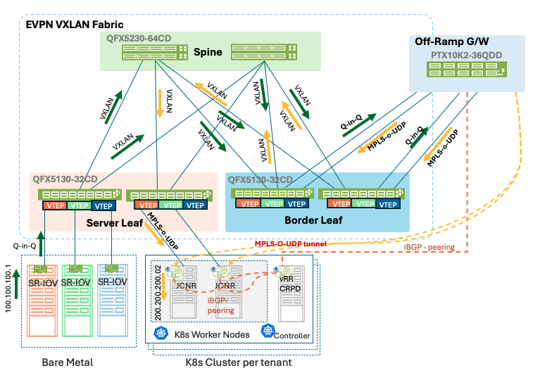
For traffic between computes (Kubernetes cluster) belonging to the same tenant and same JCNR network, the source JCNR data plane encapsulates the workload traffic using MPLS-over-UDP. The encapsulated packet is forwarded from the compute host to the attached leaf switch. If the destination workload is located on a different compute node, the leaf switch transports the traffic across the EVPN-VXLAN fabric towards the destination leaf switch. The MPLS-over-UDP packet is carried transparently across the fabric, with the leaf switches using EVPN Type-2 route information and MAC address learning to determine the forwarding path. The packet is then delivered to the destination compute host, where the receiving JCNR decapsulates the MPLS-over-UDP header and forwards the original packet to the destination workload.
As the source and destination workloads belong to the same virtual network, no Layer 3 routing lookup is required on the Off-Ramp Gateway, and the traffic remains entirely within the data center’s fabric.
Figure 33: JCNR to JCNR Same Tenant Same Network
JCNR to JCNR Same Tenant and Different Network
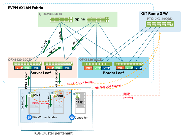
For traffic between workloads belonging to the same tenant but residing in different virtual networks (subnets), the source JCNR data plane encapsulates the traffic using MPLS-over-UDP and forwards it towards the attached leaf switch. The EVPN-VXLAN fabric transports the encapsulated traffic to the Border Leaf switch, where the VXLAN header is removed and the MPLS-over-UDP packet is forwarded towards the Off-Ramp Gateway.
The offramp gateway performs the Layer 3 lookup and route resolution between the source and destination virtual networks. Based on the tenant VRF routing information and route-leaking policies, the off-ramp gateway determines the destination JCNR endpoint and forwards the traffic back towards the fabric using MPLS-over-UDP.
The packet is then transported through the Border Leaf and EVPN-VXLAN fabric to the destination leaf switch, which delivers the packet to the destination JCNR. The receiving JCNR decapsulates the MPLS-over-UDP packet and forwards the traffic to the destination workload.
This design centralizes inter-network routing and policy enforcement on the Off-Ramp Gateway while maintaining Layer 2 transport within the EVPN-VXLAN fabric.
Figure 34: JCNR to JCNR Same Tenant Different Network
JCNR to JCNR Inter-Tenant
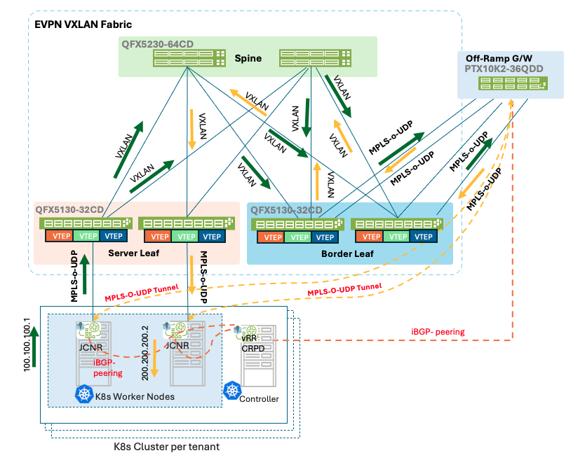
By default, tenant networks are fully isolated from one another, with each tenant hosted within its own set of VRFs and VPN route targets. Communication between workloads belonging to different tenants therefore requires traffic to traverse the Off-Ramp Gateway as its central point for policy enforcement, route leaking, and inter-VRF connectivity. For traffic originating from compute attached to a JCNR instance in one tenant communicates with workload or application attached to a JCNR instance in a different tenant, the source JCNR encapsulates the traffic using MPLS-over-UDP and forwards it towards the EVPN-VXLAN fabric. The traffic is transported across the fabric to the Border Leaf switch, where the VXLAN encapsulation is removed, and the MPLS-over-UDP packet is forwarded to the Off-Ramp Gateway. The offramp gateway performs a Layer 3 lookup within the source tenant VRF and applies the required route-leaking and policy controls to determine whether communication with the destination tenant is permitted. If inter-tenant communication is allowed as per the route policies configured on the offramp gateway, then the offramp gateway forwards the traffic into the destination tenant VRF and re-encapsulates it for delivery towards the destination JCNR endpoint. The packet is then transported through the Border Leaf and EVPN-VXLAN fabric to the destination JCNR, which decapsulates the MPLS-over-UDP header and forwards the packet to the destination workload or application.
Figure 35: JCNR to JCNR Inter Tenant Traffic Routing
Inter-tenant communication is not performed directly between JCNR instances. Traffic must traverse the Off-Ramp Gateway, where route-target policies and VRF route leaking determine whether communication between tenant environments is permitted. This ensures strict tenant isolation while providing a controlled mechanism for inter-tenant connectivity when required.
SR-IOV to SR-IOV Same Tenant and Same Subnet
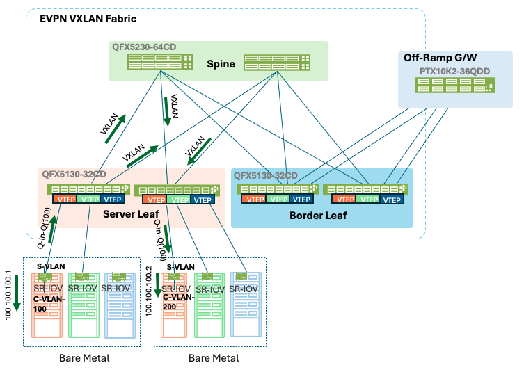
For communication between SR-IOV workloads belonging to the same tenant and residing within the same subnet, traffic is forwarded entirely at Layer 2 across the EVPN-VXLAN fabric. The workload generates a standard Ethernet frame, which is transmitted through the assigned SR-IOV Virtual Function (VF) and encapsulated using Q-in-Q tagging, where the Service VLAN (S-VLAN) identifies the tenant service and the Customer VLAN (C-VLAN) identifies the tenant network. Upon reaching the ingress leaf switch, the outer S-VLAN is mapped to the corresponding EVPN instance (MAC-VRF) and transported across the fabric. The fabric uses EVPN Type-2 MAC route advertisements to identify the location of the destination workload and forward the traffic directly to the destination leaf switch. The destination leaf restores the Q-in-Q encapsulation and forwards the packet to the destination SR-IOV workload.
As both workloads belong to the same tenant and the same subnet, no Layer 3 routing lookup is required, and the traffic does not traverse the Off-Ramp Gateway.
Figure 36: SR-IOV to SR-IOV Same Tenant Same Network Traffic Flow
SR-IOV to SR-IOV Same Tenant and Different Network
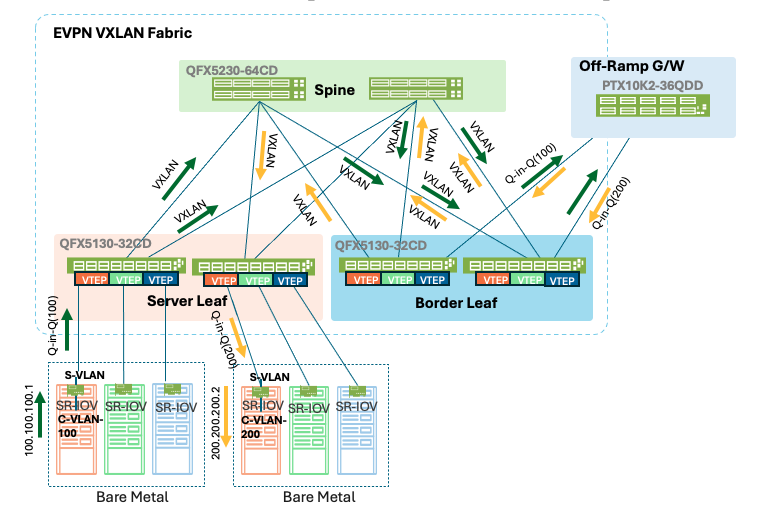
For communication between SR-IOV workloads belonging to the same tenant but residing in different networks (different C-VLANs/subnets), the traffic must be routed by the Off-Ramp Gateway. While the EVPN-VXLAN fabric provides Layer 2 transport for the SR-IOV services, it does not perform inter-subnet routing. The Off-ramp gateway acts as the centralised Layer 3 gateway and policy enforcement point for all inter-network communication.
The source SR-IOV workload transmits traffic through its SR-IOV Virtual Function (VF) using Q-in-Q encapsulation, where the Service VLAN (S-VLAN) identifies the tenant and the Customer VLAN (C-VLAN) identifies the tenant’s network. The ingress leaf switch maps the S-VLAN to the corresponding EVPN-VXLAN forwarding domain and transports the packet across the fabric to the Border Leaf. The packet is then forwarded to the Off-Ramp Gateway through the tenant-specific Layer 2 service. The offramp gateway terminates the Q-in-Q service in the corresponding tenant VRF and performs a Layer 3 lookup to determine the destination network and applies relevant routing policies to route the packet. After routing the packet to the destination tenant network, the offramp gateway forwards the traffic back into the appropriate SR-IOV Layer 2 domain, where it is transported across the EVPN-VXLAN fabric to the destination leaf switch and finally delivered to the destination SR-IOV workload.
Figure 37: SR-IOV to SR-IOV Inter-tenant Workflow
SR-IOV to SR-IOV Inter-tenant
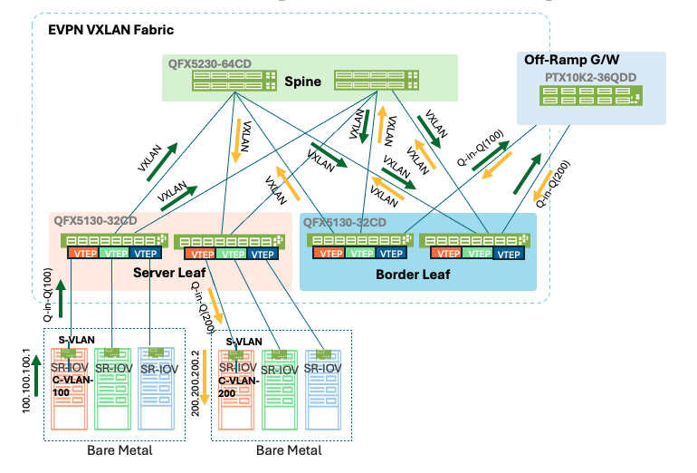
By default, SR-IOV services belonging to different tenants are isolated through dedicated S-VLANs, tenant-specific Layer 2 forwarding domains (virtual-switch instances), VRFs, and VPN route targets. Communication between workloads belonging to different tenants therefore requires traffic to traverse the Off-Ramp Gateway, which acts as the centralized Layer 3 routing and policy enforcement point for inter-tenant connectivity. The source SR-IOV workload transmits traffic through its SR-IOV Virtual Function (VF) using Q-in-Q encapsulation, where the outer Service VLAN (S-VLAN) identifies the tenant and the inner Customer VLAN (C-VLAN) identifies the tenant network. The ingress leaf switch maps the S-VLAN to the corresponding EVPN-VXLAN forwarding domain and transports the traffic through the EVPN-VXLAN fabric to the Border Leaf switch. The Border Leaf forwards the Q-in-Q traffic towards the Off-Ramp Gateway, where the packet is terminated in the source tenant VRF. The Off-Ramp Gateway performs an inter-tenant routing lookup and applies to the configured route-target import/export policies and route-leaking controls to determine whether communication between the source and destination tenants is permitted. If authorized, the traffic is forwarded into the destination tenant VRF and associated with Layer 2 service before being sent back through the Border Leaf and EVPN-VXLAN fabric towards the destination SR-IOV workload.
Figure 38: SR-IOV to SR-IOV Inter VRF Traffic
JCNR to SR-IOV
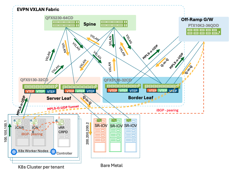
In cases where JCNR traffic is destined for SR-IOV connected systems, traffic traverses the Off-Ramp Gateway, which provides the routing transition between the JCNR MPLS-over-UDP domain and the SR-IOV Q-in-Q domain. The compute hosting the JCNR workloads generates traffic that is encapsulated using MPLS-over-UDP. The packet is forwarded to the local leaf switch and transported across the EVPN-VXLAN fabric to the Border Leaf switch. The Border Leaf removes the VXLAN encapsulation and forwards the MPLS-over-UDP packet towards the Off-Ramp Gateway. The Off-Ramp Gateway terminates the MPLS-over-UDP tunnel, performs a Layer 3 lookup within the source tenant VRF, and determines the destination SR-IOV network. Through controlled route leaking and route-target policies, the off-ramp gateway forwards the traffic into the appropriate SR-IOV VRF. The packet is then associated with the corresponding Q-in-Q service, where the appropriate S-VLAN and C-VLAN tags are applied before forwarding the traffic back through the Border Leaf and EVPN-VXLAN fabric to the destination SR-IOV workload.
Figure 39: JCNR to SR-IOV Traffic Flow
SR-IOV to JCNR
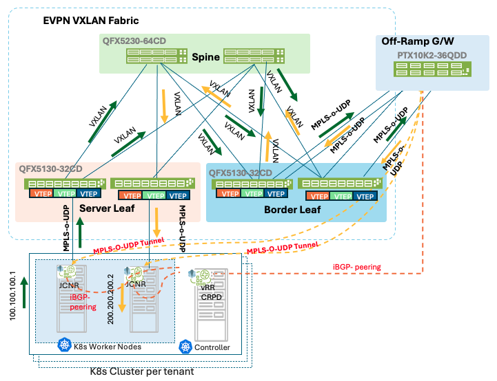
The source SR-IOV workload transmits traffic through its assigned SR-IOV Virtual Function (VF), with the packet encapsulated using Q-in-Q tagging. The outer Service VLAN (S-VLAN) identifies the tenant service, while the inner Customer VLAN (C-VLAN) identifies the tenant network. The ingress leaf switch maps the S-VLAN to the appropriate EVPN-VXLAN forwarding domain and transports the traffic across the fabric towards the Border Leaf switch.
The Border Leaf forwards the Q-in-Q traffic to the Off-Ramp Gateway, where the packet is terminated within the corresponding SR-IOV tenant VRF. The Off-Ramp Gateway performs a Layer 3 lookup and, through configured route-target import/export policies and route-leaking rules, identifies the destination JCNR network.
The traffic is then forwarded into the corresponding JCNR VRF and encapsulated as MPLS-over-UDP. The packet traverses the Border Leaf and EVPN-VXLAN fabric towards the destination compute node hosting the target JCNR instance. Upon receipt, the JCNR data plane decapsulates the MPLS-over-UDP header and forwards the original packet to the destination workload.
Figure 40: SR-IOV to JCNR Traffic