Network Deployment Model
Lab Topology
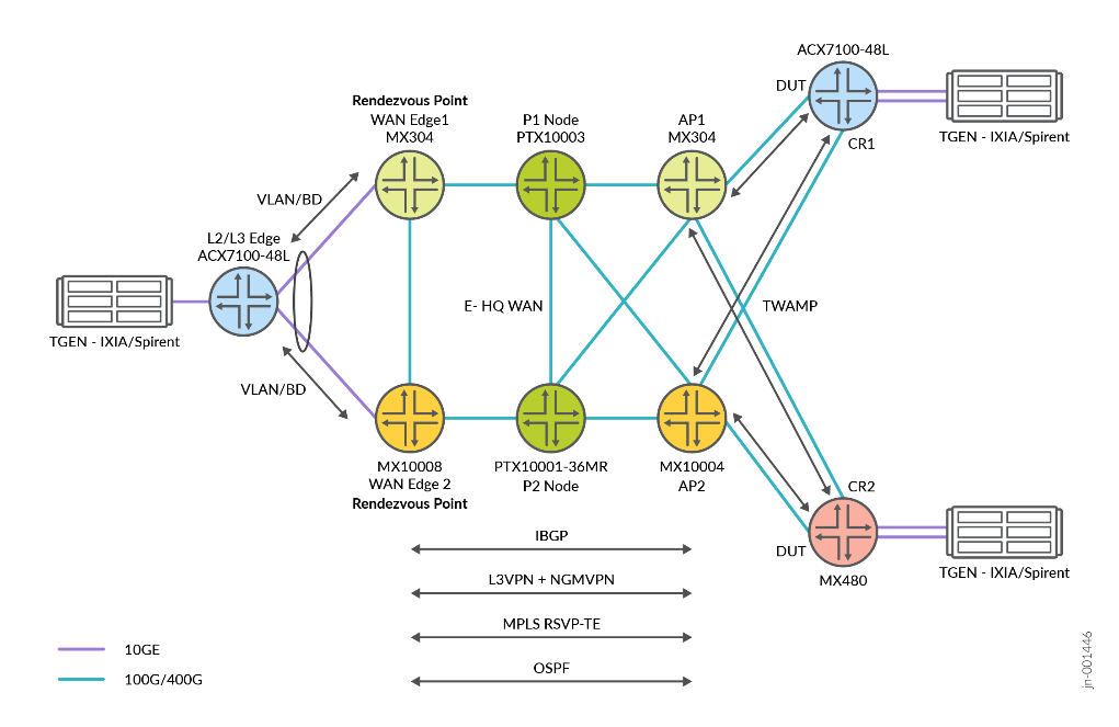
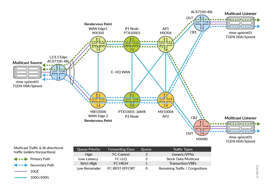
Figure 1 explains connectivity between the platforms in the Enterprise WAN for Finance and Stock Exchange JVD infrastructure. The fabric topology leverages Primary and Secondary path for multicast traffic with Anycast RP in case of node failure scenarios.
Platform Positioning
Topology definition includes:
- WANEDGE1: Device (DUT)
- AP1: Device (DUT)
- AP2: Helper Router
- CR1: Customer Router (DUT)
- CR2: Customer Router
- WANEDGE2: Helper Router
- L2/L3 Edge: Helper Router
Baseline Features
The following are list of the protocols used stock exchange WAN overlay and underlay services:
- NG-MVPN (Type 6 and Type 7)
- PIM V2 with Sparse Mode
- L3VPN
- Bridge-Domain
- MVPN with mode spt-only
- RSVP TE
- OSPF
- IBGP and EBGP
- TWAMP (SLA Monitoring)
- LLQ-COS [Multifield Classifiers]
- ANYCAST RP
- Static RP
Figure 2 shows the VPN multicast source is connected to ACX7100, which connects to WAN Edge-1 and WAN Edge-2. From the NG-MVPN signaling perspective, both routers act as Source-PE and at the other end, VPN multicast receivers connected to router AP1 and AP2 act as Receiver-PE. Following are some of the BGP routes used in NG-MVPN:
- Auto-discovery Routes: These routes help in discovering MVPN membership information within and across autonomous systems.
- Provider Tunnel Routes: These routes are used to advertise provider tunnel details.
- C-Multicast Routes: These routes are used for the exchange of customer multicast routing information.
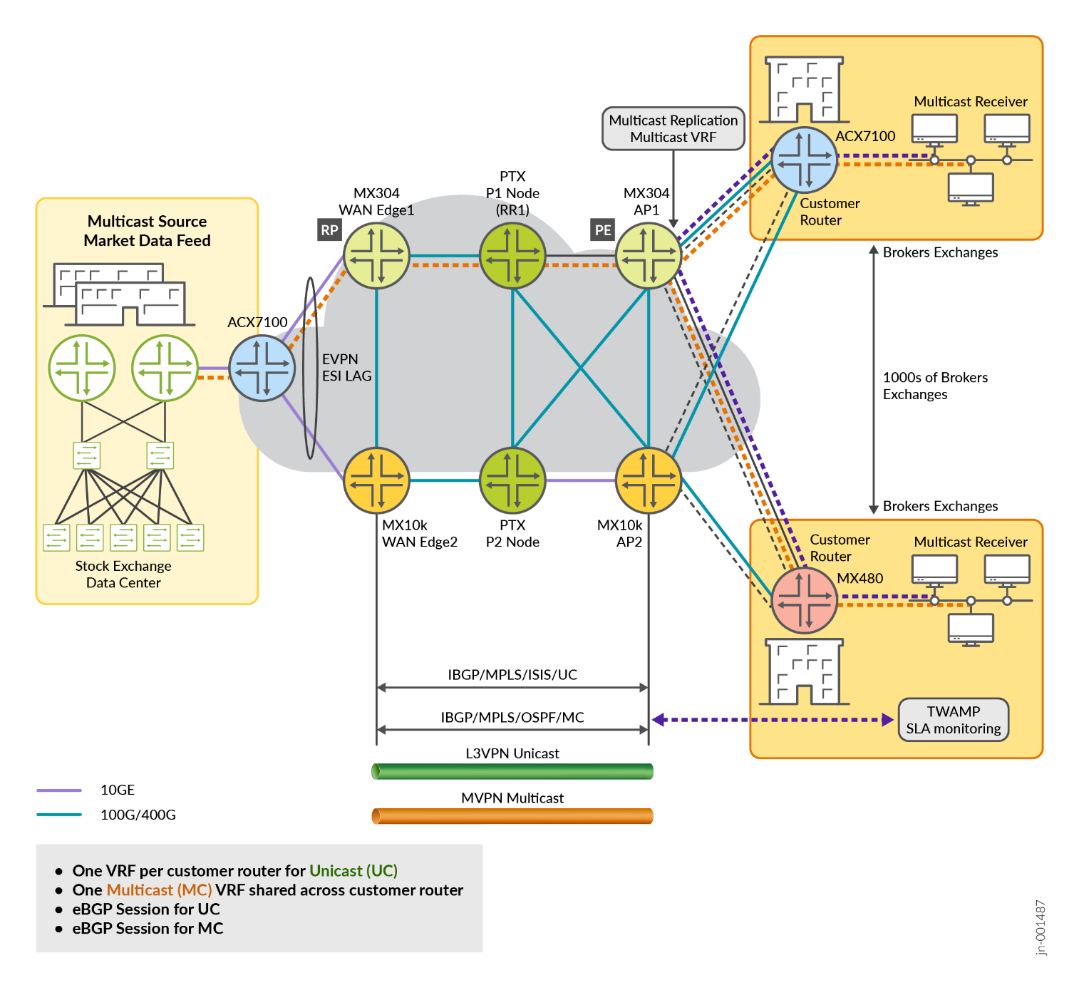
In this solution, BGP signaling is enabled with family mcast-vpn configuration to use BGP as the control plane protocol between PEs for MVPNs.
protocols {
    bgp {
        group MVPN-PEERS {
            type internal;
            family mcast-vpn {
                unicast;
            }
            neighbor 192.0.2.2;
            neighbor 192.0.2.3;
        }
    }
}
Configuration of multicast VRF at data center of the stock exchange at WANEdge-1.
    VRF1 {
        instance-type vrf;
        protocols {
            bgp {
                group CustA-STC {
                    type external;
                    local-address 172.168.101.1;
                    export adv_direct;
                    neighbor 172.168.101.2 {
                        peer-as 64513;
                    }
                }
            }
            mvpn {
                traceoptions {
                    file mvpn-VRF1.log size 1g;
                    flag all detail;
                }
                sender-site;
                mvpn-mode {
                    spt-only;
                }
                route-target {
                    import-target {
                        target target:64512:100;
                    }
                    export-target {
                        target target:64512:100;
                    }
                }
                sender-based-rpf;
                hot-root-standby {
                    source-tree;
                    min-rate {
                        rate 3m;
                        revert-delay 5;
                    }
                }
            }
            ospf {
                area 0.0.0.0 {
                    interface lo0.1;
                }
                export bgp-to-ospf;
            }
            pim {
                traceoptions {
                    file pim-VRF1.log size 1g;
                    flag all detail;
                }
                join-prune-timeout 420;
                rp {
                    local {
                        address 10.10.47.101;
                        group-ranges {
                            225.0.0.0/22;
                        }
                    }
                }
                interface lo0.1;
                interface irb.1;
            }
        }
        interface irb.1;
        interface lo0.1;
        route-distinguisher 64512:51;
        vrf-target target:64512:2;
        vrf-table-label;
        provider-tunnel {
            rsvp-te {
                label-switched-path-template {
                    default-template;
                }
            }
        }
    }
In a multicast environment, the Rendezvous Point (RP) is a crucial component for managing multicast traffic, particularly in Protocol Independent Multicast Sparse Mode (PIM-SM). The RP serves as the initial point of contact for multicast sources and receivers.
The configuration of RP in WAN Edge1 and WAN Edge2 is as follows:
                rp {
                    local {
                        address 10.10.47.101;
                        group-ranges {
                            225.0.0.0/22;
                        }
                    }
                }
                interface lo0.1;
                interface irb.1;
The configuration of RP in MVPN protocol is as follows:
    mvpn {
        traceoptions {
            file mvpn-g.log size 1g;
            flag all detail;
        }
    }
root@rtme-mx10k4-02# run show mvpn instance VRF10

MVPN instance:
Legend for neighbor state (St)
A-    Preferred upstream neighbor for inter-AS

Legend for provider tunnel
S-    Selective provider tunnel
F-    Flood NH forwarding NH
M-    Multicast Composite NH
C-    Cloned NH

Legend for c-multicast routes properties (St)
DS -- derived from (*, c-g)          RM -- remote VPN route
I -- Inactive
Family : INET

Instance : VRF10
  MVPN Mode : SPT-ONLY
  Sender-Based RPF: Disabled. Reason: Not enabled by configuration.
  Hot Root Standby: Disabled. Reason: Not enabled by configuration.
  Provider tunnel: I-P-tnl:RSVP-TE P2MP:7.7.7.7, 44721,7.7.7.7
  Neighbor                      Inclusive Provider Tunnel                           Label-In    St             Segment
  5.5.5.5                       RSVP-TE P2MP:5.5.5.5, 17207,5.5.5.5                     1065
  9.9.9.9                       RSVP-TE P2MP:9.9.9.9, 32163,9.9.9.9                     1065

  C-mcast IPv4 (S:G)            Provider Tunnel                                     Label-In    St    FwdNh    Segment
  0.0.0.0/0:225.0.36.0/32       Primary unbound
  172.168.102.2/32:225.0.36.0/32 RSVP-TE P2MP:9.9.9.9, 32163,9.9.9.9                    1065           M-0x0
Optimum Replication
Multicast tunnels are either ingress replication tunnels or Point to MultiPoint (P2MP) tunnels. The solution supports optimum replication for both Intra-subnet and Inter-subnet IP multicast traffic.
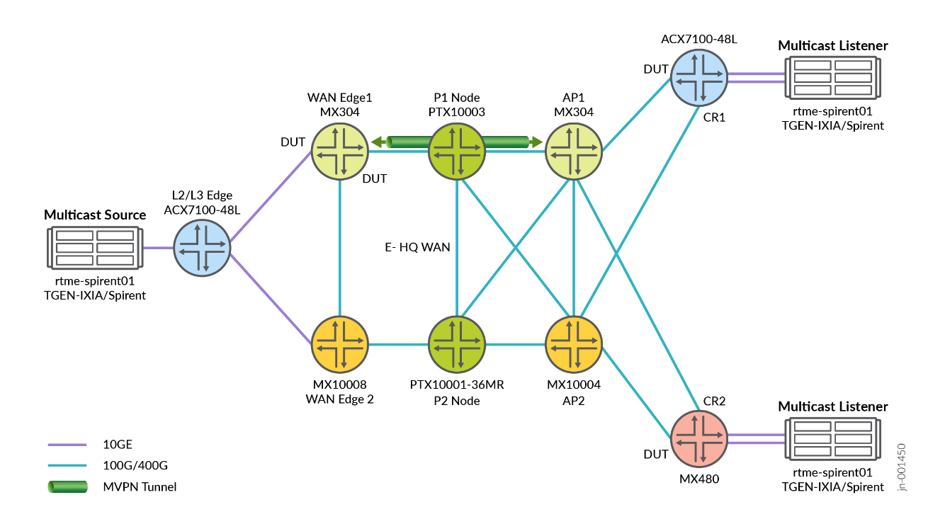
Ethernet VPN (EVPN) connects dispersed customer sites using a Layer 2 virtual bridge. In Figure 3 , EVPN with Single-Active solution is enabled with Designated Forwarder (DF) and Non-Designated Forwarders (non-DF) PE’s. This solution supports all EVPN service interfaces listed in Section 6 of [RFC7432]:
- VLAN-based service interface
- VLAN-bundle service interface
- VLAN-aware bundle service interface
In this JVD solution is used VLAN-based service interface model. EVPN ESI simplifies complex network designs by:
- Reducing network complexity and eliminating multiple redundancy protocols
- Providing a unified approach to multi-homing
- Minimizing configuration overhead
- Enabling centralized management of network segments
ae0 {
        flexible-vlan-tagging;
        mtu 1522;
        encapsulation flexible-ethernet-services;
        esi {
            00:11:11:11:11:11:12:12:12:12;
            single-active;
            df-election-granularity {
                per-esi {
                    lacp-oos-on-ndf;
                }
            }
            df-election-type {
                preference {
                    value 150;
                }
            }
        }
        aggregated-ether-options {
            link-speed 10g;
            lacp {
                active;
                system-priority 100;
                system-id 00:00:00:00:00:10;
            }
        }
        unit 1 {
            description "Connection to PE1_to_CE1_for_CR1_1";
            encapsulation vlan-bridge;
            vlan-id 10;
            esi {
                00:01:71:81:11:12:a1:00:00:01;
                single-active;
                df-election-type {
                    preference {
                        value 150;
                    }
                }
            }
        }
        unit 2 {
            description "Connection to PE1_to_CE1_for_CR1_2";
            encapsulation vlan-bridge;
            vlan-id 11;
            esi {
                00:02:71:81:11:12:a1:00:00:02;
                single-active;
                df-election-type {
                    preference {
                        value 150;
                    }
                }
            }
        }
        unit 3 {
            …
        }
        unit 4 {
                        …
        }
        unit 5 {
            …}
        unit 6 {
            …}
        unit 7 {
            …}
        unit 8 {
            …}
        unit 9 {
            …}

        unit 10 {
            encapsulation vlan-bridge;
            vlan-id 19;
            esi {
                00:22:71:81:11:12:a1:00:00:01;
                single-active;
                df-election-type {
                    preference {
                        value 150;
                    }
                }
            }
        }
        unit 20 {
            vlan-id 20;
            family inet {
                address 192.168.200.10/24;
            }
        }
        unit 21 {
            encapsulation vlan-bridge;
            vlan-id 21;
            esi {
                00:22:71:81:11:12:a1:00:00:21;
                single-active;
                df-election-type {
                    preference {
                        value 150;
                    }
                }
            }
        }
        unit 22 {
            encapsulation vlan-bridge;
            vlan-id 22;
            esi {
                00:22:71:81:11:12:a1:00:00:22;
                single-active;
                df-election-type {
                    preference {
                        value 150;
                    }
                }
            }
        }
        unit 23 {
            encapsulation vlan-bridge;
            vlan-id 23;
            esi {
                00:23:71:81:11:12:a1:00:00:23;
                single-active;
                df-election-type {
                    preference {
                        value 150;
                    }
                }
            }
        }
        unit 50 {
            encapsulation vlan-bridge;
            vlan-id 50;
            esi {
                00:03:03:03:03:03:03:03:03:01;
                all-active;
            }
        }
    }
L3 VPN Configuration
In Next-Generation Multicast VPNs (NG-MVPNs), the underlying Layer 3 VPN (L3VPN) model provides the foundational unicast infrastructure and core network, onto which NG-MVPN builds the capability to transport multicast traffic efficiently. NG-MVPN extends the familiar MPLS L3VPN service by unifying the control plane for both unicast and multicast using BGP, reducing the complexity and improving scalability compared to older MVPN architectures. Figure x shows the traffic flow from the customer to the stock exchange data center and vice versa. There are separate VRFs from unicast and Multicast services.
.png)
Following is the L3 VPN configuration for multicast traffic.
    VRF10 {
        instance-type vrf;
        protocols {
            bgp {
                group CustA-STC-10 {
                    type external;
                    local-address 172.168.102.1;
                    export adv_direct;
                    neighbor 172.168.102.2 {
                        peer-as 64513;
                    }
                }
            }

            mvpn {
                traceoptions {
                    file mvpn-VRF10.log size 1g;
                    flag all detail;
                }
                sender-site;
                mvpn-mode {
                    spt-only;
                }
                route-target {
                    import-target {
                        target target:64512:109;
                    }
                    export-target {
                        target target:64512:109;
                    }
                }
                sender-based-rpf;
                hot-root-standby {
                    source-tree;
                    min-rate {
                        rate 3m;
                        revert-delay 5;
                    }
                }
            }
            ospf {
                area 0.0.0.0 {
                    interface lo0.10;
                }
                export bgp-to-ospf;
            }
            pim {
                traceoptions {
                    file pim-VRF10.log size 1g;
                    flag all detail;
                }
                join-prune-timeout 420;
                rp {
                    local {
                        address 10.10.47.110;
                        group-ranges {
                            225.0.36.0/22;
                        }
                    }
                }
                interface lo0.10;
                interface irb.10;
            }
        }
        interface irb.10;
        interface lo0.10;
        route-distinguisher 64512:60;
        vrf-target target:64512:11;
        vrf-table-label;
        provider-tunnel {
            rsvp-te {
                label-switched-path-template {
                    default-template;
                }
            }
        }
    }
Here is the configuration for L3 VPNS for unicast traffic
    VRF21 {
        instance-type vrf;
        protocols {
            bgp {
                group STC_AF {
                    type external;
                    local-address 40.40.2.1;
                    export adv_direct;
                    neighbor 40.40.2.2 {
                        peer-as 64513;
                    }
                }
            }
        }
        interface irb.21;
        route-distinguisher 64512:21;
        vrf-target target:64512:21;
        vrf-table-label;
    }
Class of Service
In Juniper router, we support multiple levels of transmission priority, which in order of increasing priority are low, low-medium, low-high, medium-low, medium-high, high, strict-high, and low-latency. This allows the software to service higher-priority queues before lower-priority queues. Which transmission priority levels that are supported can vary depending on the platform and software release. LLQ enables delay-sensitive data to have preferential treatment over other traffic. A low-latency queue has the highest priority over any other priority queues, including strict-high queues, as well as a low delay scheduling profile.
In this solution Class of Service( CoS ) with a multifield classifier applied on multicast and other services use the following queue priorities. CoS is configured with multifield classifiers that prioritize multicast traffic with a low-latency priority designation, while assigning a lower priority to all remaining services.
The following table provides queue priority details:
| Queue Priority | Forwarding Class | Queue | Traffic Types |
|---|---|---|---|
| High | FC-Control | 3 | Generic/VPNs |
| Low-Latency | FC-LLQ | 2 | Stock Data/Multicast |
| Strict-High | FC-HIGH | 1 | Transaction/VRFs |
Following sample COS configuration can be applied on WAN edge-1 and WAN edge-2.
    Filter_MF {
        firewall {
            family inet {
                filter mfc-filter {
                    interface-specific;
                    term stock_exch {
                        from {
                            destination-address {
                                225.0.0.0/16;
                            }
                        }
                        then {
                            loss-priority low;
                            forwarding-class FC-LLQ;
                        }
                    }
                    term accept-all-else {
                        then accept;
                    }
                }
                filter mfc-filter1 {
                    interface-specific;
                    term stock_exch {
                        from {
                            destination-address {
                                20.20.2.22/32;
                            }
                        }
                        then {
                            loss-priority low;
                            forwarding-class FC-HIGH;
                        }
                    }
                    term accept-all-else {
                        then accept;
                    }
                }
                filter mfc-filter2 {
                    interface-specific;
                    term stock_exch {
                        from {
                            destination-address {
                                20.20.4.22/32;
                            }
                        }
                        then {
                            loss-priority low;
                            forwarding-class BEST-EFFORT;
                        }
                    }
                    term accept-all-else {
                        then accept;
                    }
                }
                filter mfc-filter3 {
                    interface-specific;
                    term stock_exch {
                        from {
                            destination-address {
                                20.20.3.22/32;
                            }
                        }
                        then {
                            loss-priority low;
                            forwarding-class CONTROL;
                        }
                    }
                    term accept-all-else {
                        then accept;
                    }
                }
            }
        }
    }
    Int_MF {
        interfaces {
            irb {
                unit 10 {
                    family inet {
                        filter {
                            input mfc-filter;
                        }
                    }
                }
                unit 21 {
                    family inet {
                        filter {
                            input mfc-filter1;
                        }
                    }
                }
                unit 22 {
                    family inet {
                        filter {
                            input mfc-filter3;
                        }
                    }
                }
                unit 23 {
                    family inet {
                        filter {
                            input mfc-filter2;
                        }
                    }
                }
                unit 1 {
                    family inet {
                        filter {
                            input mfc-filter;
                        }
                    }
                }
                unit 2 {
                   …}
                unit 3 {
                      …}
                unit 4 {
                      …}
                unit 5 {
                      …}
                unit 6 {
                      …
                        }
                unit 7 {
                      …}
                unit 8 {
                      …}
                unit 9 {
                      …}


        }
    }
    COS_MF {
        class-of-service {
            classifiers {
                exp EXP {
                    forwarding-class FC-HIGH {
                        loss-priority low code-points 001;
                    }
                    forwarding-class BEST-EFFORT {
                        loss-priority low code-points 000;
                    }
                    forwarding-class CONTROL {
                        loss-priority low code-points 011;
                    }
                    forwarding-class FC-LLQ {
                        loss-priority low code-points 010;
                    }
                }
            }
            forwarding-classes {
                class FC-HIGH queue-num 1;
                class BEST-EFFORT queue-num 0;
                class CONTROL queue-num 3;
                class FC-LLQ queue-num 2;
            }
            interfaces {
                et-0/0/4 {
                    scheduler-map sched-map;
                    unit 0 {
                        classifiers {
                            exp EXP;
                        }
                        rewrite-rules {
                            exp EXP;
                        }
                    }
                }
                xe-0/0/1:1 {
                    scheduler-map sched-map;
                    unit 0 {
                        classifiers {
                            exp EXP;
                        }
                        rewrite-rules {
                            exp EXP;
                        }
                    }
                }
                et-0/0/2 {
                    scheduler-map sched-map;
                }
                ae0 {
                    scheduler-map sched-map;
                }
            }
            rewrite-rules {
                exp EXP {
                    forwarding-class FC-HIGH {
                        loss-priority low code-point 001;
                    }
                    forwarding-class BEST-EFFORT {
                        loss-priority low code-point 000;
                    }
                    forwarding-class CONTROL {
                        loss-priority low code-point 011;
                    }
                    forwarding-class FC-LLQ {
                        loss-priority low code-point 010;
                    }
                }
            }
            scheduler-maps {
                sched-map {
                    forwarding-class BEST-EFFORT scheduler s0;
                    forwarding-class FC-HIGH scheduler s1;
                    forwarding-class FC-LLQ scheduler s2;
                    forwarding-class CONTROL scheduler s3;
                }
            }
            schedulers {
                s0 {
                    transmit-rate {
                        remainder;
                    }
                    priority low;
                }
                s1 {
                    transmit-rate percent 20;
                    shaping-rate percent 20;
                    priority low;
                }
                s2 {
                    transmit-rate percent 40;
                    priority strict-high;
                }
                s3 {
                    transmit-rate percent 20;
                    shaping-rate percent 20;
                    priority low;
                }
            }
        }
    }
Following sample configuration can be applied on an access point.
class-of-service {
    classifiers {
        exp EXP {
            forwarding-class BEST-EFFORT {
                loss-priority low code-points 000;
            }
            forwarding-class CONTROL {
                loss-priority low code-points 011;
            }
            forwarding-class FC-HIGH {
                loss-priority low code-points 001;
            }
            forwarding-class FC-LLQ {
                loss-priority low code-points 010;
            }
        }
    }
    forwarding-classes {
        class FC-HIGH queue-num 1;
        class BEST-EFFORT queue-num 0;
        class CONTROL queue-num 3;
        class FC-LLQ queue-num 2;
    }
    routing-instances {
        <VRF*> {
            classifiers {
                no-default;
            }
        }
        VRF1 {
            classifiers {
                no-default;
            }
        }
        VRF10 {
            classifiers {
                no-default;
            }
        }
        VRF2 {
            classifiers {
                no-default;
            }
        }
        VRF21 {
            classifiers {
                no-default;
            }
        }
        VRF22 {
            classifiers {
                no-default;
            }
        }
        VRF23 {
            classifiers {
                no-default;
            }
        }
        VRF3 {
            …}
        VRF4 {
            …}
        VRF5 {
…}
        VRF6 {
…}
        VRF7 {
…}
        VRF8 {
…}
        VRF9 {
…}
    rewrite-rules {
        exp EXP {
            forwarding-class BEST-EFFORT {
                loss-priority low code-point 000;
            }
            forwarding-class CONTROL {
                loss-priority low code-point 011;
            }
            forwarding-class FC-HIGH {
                loss-priority low code-point 001;
            }
            forwarding-class FC-LLQ {
                loss-priority low code-point 010;
            }
        }
    }
}
You can define Class of Service in the following roles, which are suitable for this JVD solution.
- Classification:
- Behavior Aggregate classification is based on received code points
- 802.1p, DSCP, and EXP classification is based on received ingress packet headers
- Fixed classification is based on forwarding class mapping
For guaranteed ultra-low end-to-end latency between the Customer Equipment (CE) and the Provider Equipment (PE) as well as for overall Low Latency Quality (LLQ) use cases. For more information, see JVD-5G-FH-COS-02-02 .
Following is the sample configuration for multifield classification.
Filter_MF {
        firewall {
            family inet {
                filter mfc-filter {
                    term stock_exch {
                        from {
                            destination-address {
                                225.0.0.0/16;
                            }
                        }
                        then {
                            loss-priority low;
                            forwarding-class FC-LLQ;
                        }
                    }
                    term accept-all-else {
                        then accept;
                    }
                }
                filter mfc-filter1 {
                    term stock_exch {
                        from {
                            destination-address {
                                20.20.2.22/32;
                            }
                        }
                        then {
                            loss-priority low;
                            forwarding-class FC-HIGH;
                        }
                    }
                    term accept-all-else {
                        then accept;
                    }
                }
                filter mfc-filter2 {
                    term stock_exch {
                        from {
                            destination-address {
                                20.20.3.22/32;
                            }
                        }
                        then {
                            loss-priority low;
                            forwarding-class CONTROL;
                        }
                    }
                    term accept-all-else {
                        then accept;
                    }
                }
                filter mfc-filter3 {
                    term stock_exch {
                        from {
                            destination-address {
                                20.20.4.22/32;
                            }
                        }
                        then {
                            loss-priority low;
                            forwarding-class BEST-EFFORT;
                        }
                    }
                    term accept-all-else {
                        then accept;
                    }
                }
            }
        }
    }
    COS_MF {
        class-of-service {
            classifiers {
                exp EXP {
                    forwarding-class BEST-EFFORT {
                        loss-priority low code-points 000;
                    }
                    forwarding-class CONTROL {
                        loss-priority low code-points 011;
                    }
                    forwarding-class FC-HIGH {
                        loss-priority low code-points 001;
                    }
                    forwarding-class FC-LLQ {
                        loss-priority low code-points 010;
                    }
                }
            }
            forwarding-classes {
                class AF queue-num 1;
                class BEST-EFFORT queue-num 0;
                class CONTROL queue-num 3;
                class EF queue-num 2;
                class FC-HIGH queue-num 1;
                class FC-LLQ queue-num 2;
            }
            interfaces {
                et-0/1/2 {
                    scheduler-map sched-map;
                    unit 0 {
                        classifiers {
                            exp EXP;
                        }
                        rewrite-rules {
                            exp EXP;
                        }
                    }
                }
                et-0/0/0 {
                    scheduler-map sched-map;
                    unit 0 {
                        classifiers {
                            exp EXP;
                        }
                        rewrite-rules {
                            exp EXP;
                        }
                    }
                }
                et-0/0/1 {
                    scheduler-map sched-map;
                    unit 0 {
                        classifiers {
                            exp EXP;
                        }
                        rewrite-rules {
                            exp EXP;
                        }
                    }
                }
                et-0/0/5 {
                    scheduler-map sched-map;
                }
            }
            rewrite-rules {
                exp EXP {
                    forwarding-class BEST-EFFORT {
                        loss-priority low code-point 000;
                    }
                    forwarding-class CONTROL {
                        loss-priority low code-point 011;
                    }
                    forwarding-class FC-HIGH {
                        loss-priority low code-point 001;
                    }
                    forwarding-class FC-LLQ {
                        loss-priority low code-point 010;
                    }
                }
            }
            scheduler-maps {
                sched-map {
                    forwarding-class BEST-EFFORT scheduler s0;
                    forwarding-class AF scheduler s1;
                    forwarding-class EF scheduler s2;
                    forwarding-class CONTROL scheduler s3;
                    forwarding-class FC-HIGH scheduler s1;
                    forwarding-class FC-LLQ scheduler s2;
                }
            }
            schedulers {
                s0 {
                    transmit-rate {
                        remainder;
                    }
                    buffer-size {
                        remainder;
                    }
                    priority low;
                }
                s1 {
                    transmit-rate percent 40;
                    buffer-size percent 30;
                    priority low;
                }
                s2 {
                    shaping-rate percent 40;
                    buffer-size percent 10;
                    priority low-latency;
                }
                s3 {
                    shaping-rate percent 5;
                    buffer-size percent 5;
                    priority high;
                }
            }
        }
    }
    Int_MF {
        interfaces {
            et-0/1/5 {
                unit 1 {
                    family inet {
                        filter {
                            output mfc-filter;
                        }
                    }
                }
                unit 2 {
…}
                unit 3 {
…}
                unit 4 {
…}
                unit 5 {
…}
                unit 6 {
…}
                unit 7 {
                    …
                }
                unit 8 {
                    …
                }
                unit 9 {
                    …}
                unit 10 {
}
                unit 12 {
…}
                unit 13 {
…}
                unit 14 {
…}
            }
            et-0/1/1 {
                unit 1 {
                    family inet {
                        filter {
                            output mfc-filter;
                        }
                    }
                }
                unit 2 {
                    family inet {
                        filter {
                            output mfc-filter;
                        }
                    }
                }
                unit 3 {
                    …}
                unit 4 {
…}
                unit 5 {
…}
                unit 6 {
…}
                unit 7 {
…}
                unit 8 {
…}
                unit 9 {
…}

                unit 10 {
                    family inet {
                        filter {
                            output mfc-filter;
                        }
                    }
                }
            }
        }
    }
Two-Way Active Measurement Protocol (TWAMP)
TWAMP is an open protocol that measures network performance between two devices in a network. It helps in measuring the network performance between the two devices in a round trip that supports TWAMP implementation and is used to check the Service Level Agreement (SLA) compliance. Figure 7 shows implementation of TWAMP between AP and CR nodes.
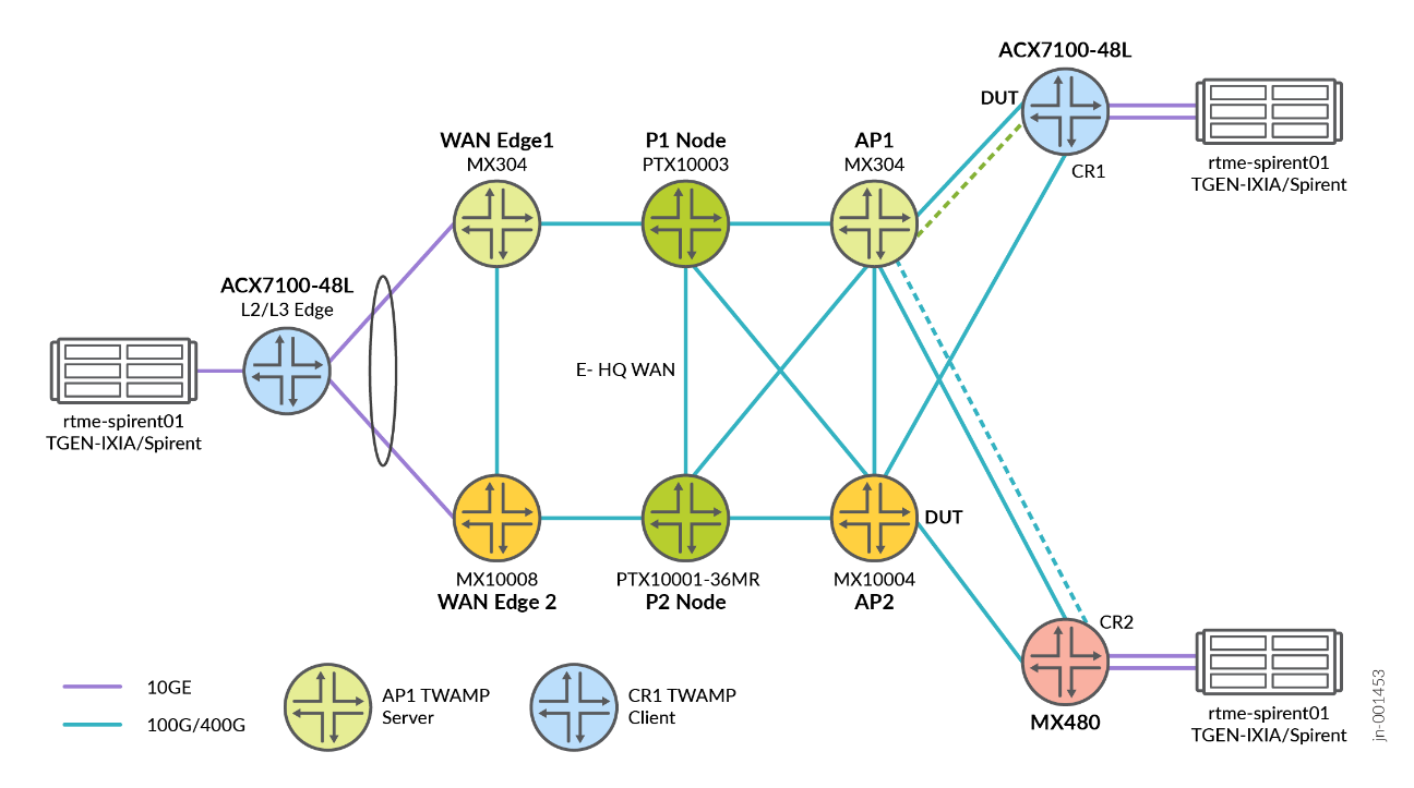
TWAMP is a sophisticated network performance measurement protocol that evolved from its predecessor, One-Way Active Measurement Protocol (OWAMP). It is like an advanced diagnostic tool for network health.
Following is a sample server-side configuration of AP1, which is acting as the Server in this network topology.
services {
    rpm {
        twamp {
            server {
                routing-instance-list {
                    <VRF*> {
                        port 862;
                    }
                }
                authentication-mode none;
                port 1862;
                client-list Client1 {
                    address {
                        10.60.60.1/32;
                        192.168.110.2/32;
                    }
                }
                client-list Client2 {
                    address {
                        192.168.3.2/32;
                    }
                }
                light;
            }
        }
    }
}
Reference Architecture Implications
- Refer Metro Ethernet Business Services for EVPN-VPWS/FXC/EVPN-ELAN and co-existing with traditional VPN services including multi-site VPLS, Hot-Standby L2Circuit, L2VPN, and L3VPN with DIA.
- Refer Metro as a Service MEF 3.0 for further details on EVPN-VPWS, EVPN-FXC, EVPN-ELAN, VPLS, L2Circuit, and L2VPN over a color-aware SR-MPLS Inter-AS topology.
- Refer Class of Service in 5G Networks for ultra-low end-to-end latency between the Customer Equipment (CE) and the Provider Equipment (PE) as well as for overall Low Latency Quality (LLQ) usage nodes.