Solution Design and Architecture
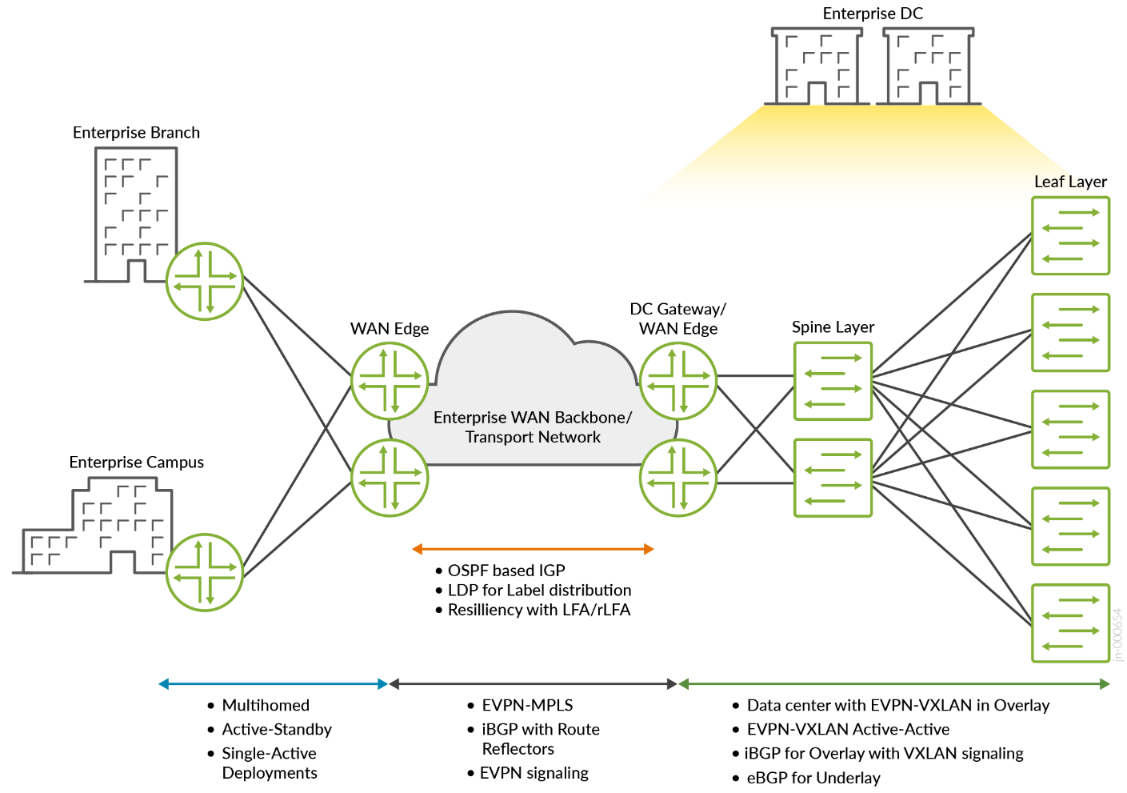
Figure 1 shows a typical enterprise network with a private data center. Remember that the data center uses a spine and leaf architecture. Leaf devices connect servers to the network. The spine layer provides connectivity to other leaf devices and the data center edge/gateway devices that connect the data center to the WAN. External BGP (EBGP) is the EVPN-VXLAN signaling protocol within the data center. In the WAN, EVPN-MPLS services connect remote campus and branch offices to the data center. Seamless interconnecting of these two services happens on the data center edge/gateway devices.
The building blocks for this JVD architecture (see Figure 1) include:
- OSPF routing
- LDP for label distribution
- Internal BGP (iBGP) between PE and Route-Reflector (RR) node for EVPN signalling
- EVPN-MPLS
- Multihomed Single-Active and Single-Homed
- Resiliency with Loop-Free Alternates (LFA)/Remote LFA (rLFA)
Enterprise data center technologies include:
- EVPN-VXLAN overlay
- EBGP underlay
The data center reference design is explained in the Data Center EVPN VXLAN Fabric Architecture Guide.
Packet Flow
Outbound traffic originating from the private enterprise data center server is encapsulated in unicast Layer 2 Ethernet frames and forwarded to a leaf device. The leaf device encapsulates the packet inside of an EVPN-VXLAN header and the packet is forwarded through the data center network until reaching an edge/gateway device. The edge/gateway devices are capable of both EVPN-VXLAN and EVPN-MPLS encapsulation. The edge/gateway device removes the VXLAN header, performs a forwarding lookup, encapsulates the packet in an EVPN-MPLS header, and forwards the packet on the WAN. The packets traverse the nodes in the enterprise WAN backbone where MPLS push, pop, and swap operations are performed. When an EVPN-MPLS encapsulated packet reaches the remote WAN edge device, the EVPN-MPLS header is stripped, and the original Ethernet frame is forwarded into the remote L2 domain. See Figure 2.
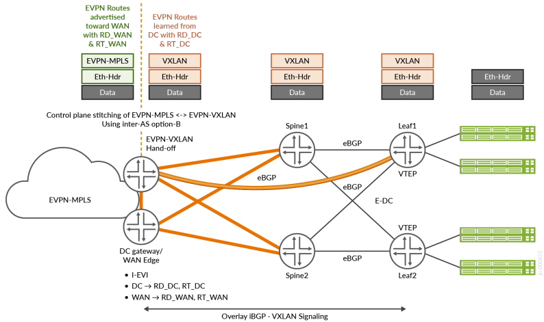
The control plane on the data center edge/gateway devices maintain a single MAC Forwarding Information Base (FIB) for both the data center and WAN networks. This FIB enables the device to interconnect the EVPN tunnels in the data center and the WAN.
This Junos OS configuration snippet enables these capabilities on a data center gateway device. For complete configuration, contact your Juniper Networks representative.
ERB_InterConnect_VAware_Instance1 {
        instance-type virtual-switch;
        protocols {
            evpn {
                encapsulation vxlan;
                default-gateway no-gateway-community;
                extended-vni-list [ 3500 3501 ];
                interconnect {
                    vrf-target target:3500:3500;
                    route-distinguisher 1.1.1.6:3500;
                    esi {
                        00:35:45:55:65:75:85:95:05:25;
                        all-active;
                    }
                    interconnected-vlan-list [ 3500 3501 ];
                    encapsulation mpls;
                }
                vni-options {
                    vni 3500 {
                        vrf-target target:3:3500;
                    }
                    vni 3501 {
                        vrf-target target:3:3501;
                    }
                }
            }
        }
        vtep-source-interface lo0.0;
        bridge-domains {
            BD3500 {
                vlan-id 3500;
                routing-interface irb.3500;
                vxlan {
                    vni 3500;
                }
            }
            BD3501 {
                vlan-id 3501;
                routing-interface irb.3501;
                vxlan {
                    vni 3501;
                }
            }
        }
        route-distinguisher 10.10.10.6:5036;
        vrf-target target:100:36;
    }
Inbound data center traffic arrives at an edge/gateway device EVPN-MPLS encapsulated. The edge/gateway device removes the EVPN-MPLS header and performs a forwarding lookup to determine the next-hop EVPN-VXLAN tunnel. The traffic is EVPN-VXLAN encapsulated and forwarded to an application endpoint. Figure 3 depicts the end-to-end packet flow in the network.
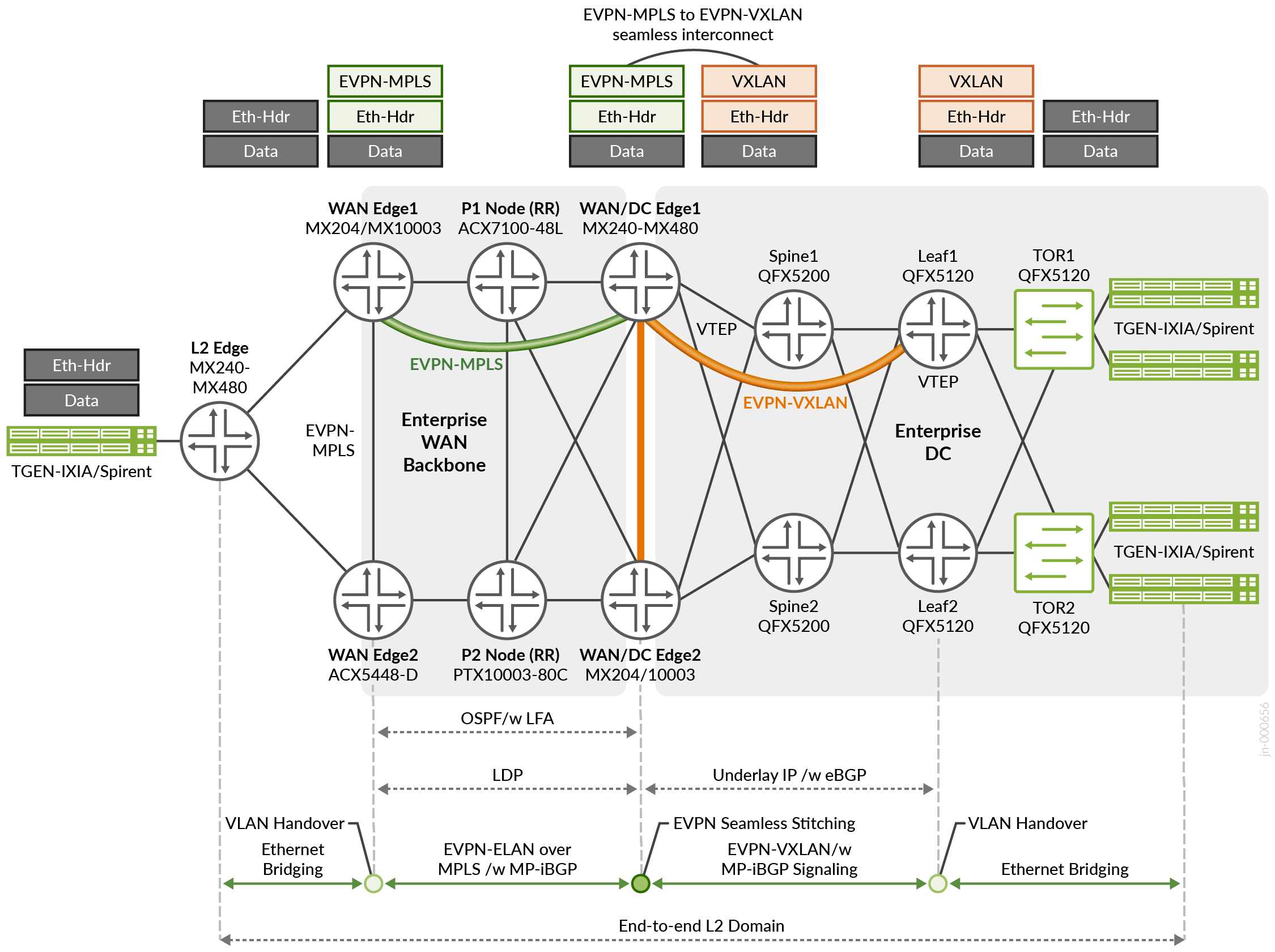
In summary, the packet flow from EVPN-VXLAN to EVPN-MPLS is described by the following process:
- Leaf nodes encapsulate Ethernet frames into EVPN-VXLAN packets.
- EVPN-VXLAN encapsulated packets are routed through the data center network to an edge/gateway device.
- The EVPN-VXLAN header is removed.
- Ethernet frames are encapsulated in EVPN-MPLS.
- WAN MPLS-based forwarding occurs.
- Remote WAN edge device removes the EVPN-MPLS header.
- Original Ethernet frame is forwarded to the destination host.