Validation Framework
Test Bed
The test topology used for the evaluation of this JVD is documented in Figure 1:
Figure 1: Test Bed for Phase
1+ 2 of this JVD
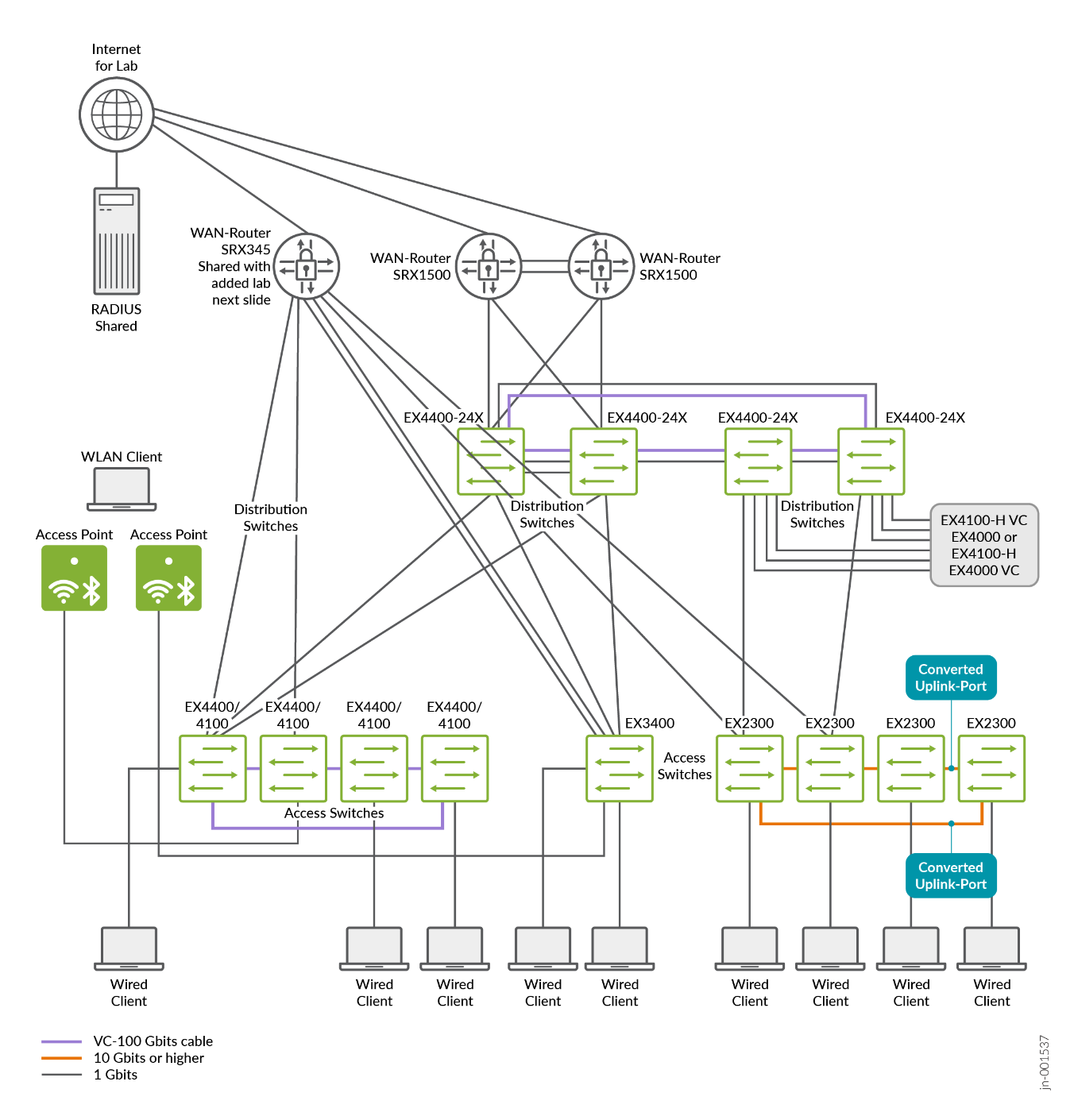
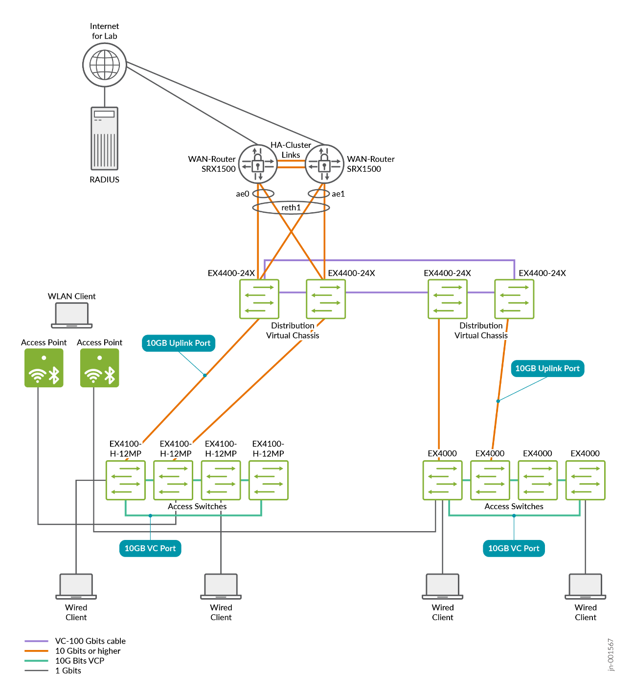
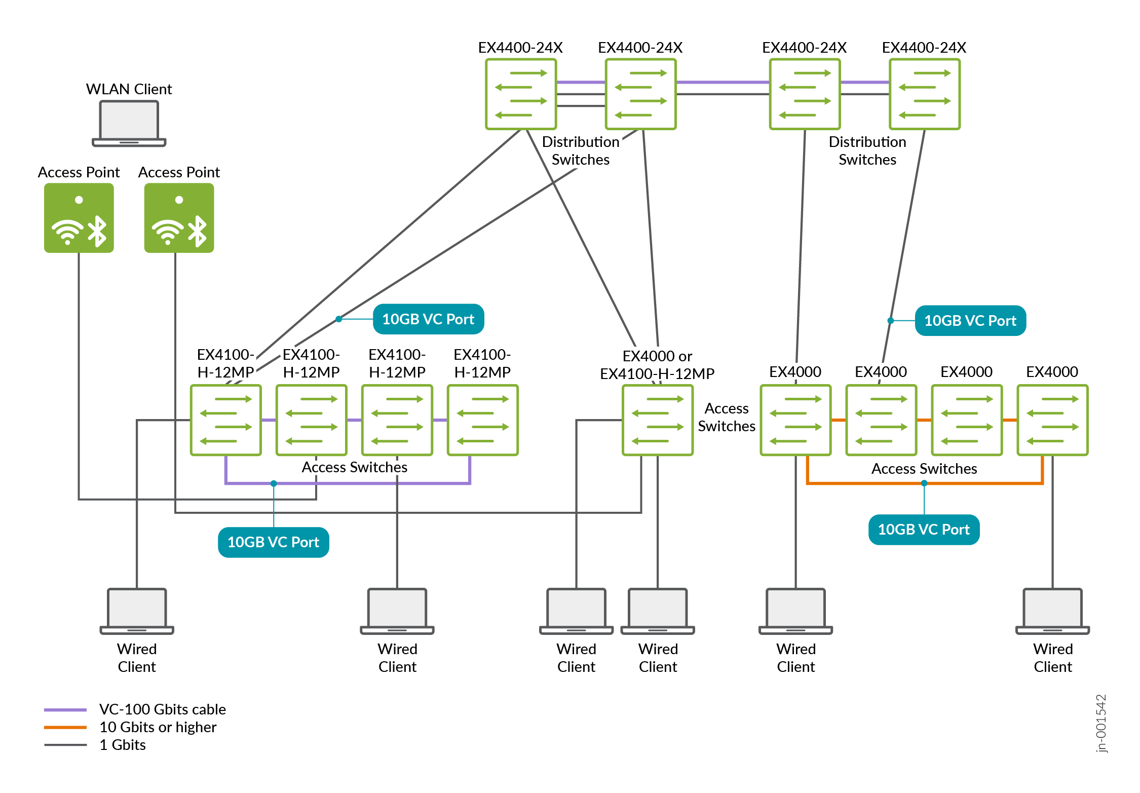
Figure 2: Lab extension to test EX4000 and
EX4100-H
The current lab design includes the following:
- Branch use cases:
- Single standalone switch (Juniper Networks® EX3400 Switch) attached directly to WAN router.
- Single standalone switch (Juniper Networks® EX4000 Switch or Juniper Networks® EX4100-H Switch) attached directly to WAN router.
- One four-member Virtual Chassis access switch based on Juniper Networks® EX4400 Switch or EX4100 Switch.
- One four-member Virtual Chassis access switch based on Juniper Networks® EX2300 Switch.
- One four-member Virtual Chassis access switch based on EX4000 Switch.
- One four-member Virtual Chassis access switch based on EX4100-H Switch.
- One four-member Virtual Chassis distribution switch based on Juniper Networks® EX4400-24X Switch.
- Two access points for limited Wi-Fi testing.
- EVPN multihoming campus fabric (not within the scope of this
JVD):
- Two redundant distribution switches acting as a collapsed core.
- One four-member Virtual Chassis access switch acting as a leaf.
- One standalone access switch acting as a leaf.
- Four distribution switches acting as collapsed core in a ring.
- Four four-member Virtual Chassis Access Switch acting as a leaf.
- Two standalone access switches acting as a leaf.
- Two redundant distribution switches acting as a collapsed core.
- WAN router integration:
- Layer 3 gateways on the WAN router.
- IEEE 802.3ad LAG-based trunks.
- Attached to
- Distribution switches.
- Directly to the access switches.
- Redundant WAN router design
- Two Juniper SRX firewalls in a high availability configuration.
- The WAN router is also managed by the Juniper Mist cloud (WAN edge SRX operating in standalone mode).
- The DHCP server is located on the WAN router or the WAN router is performing DHCP relay.
- Layer 3 gateways on the WAN router.
- Wireless access points
- Locally attached to the access switches with PoE.
- Various wireless clients.
- Basic wireless roaming.
- Wired clients
- Virtual machines or testing equipment attached to the access switches.
- RADIUS server
- Server location
- Local server attached to the underlay or VPN network.
- Juniper Mist™ Access Assurance via public cloud.
- Authentication for the following clients:
- Wired clients attached to access switches.
- Wi-Fi clients using the access points.
- Authentication based on clients:
- MAC address.
- 802.1X EAP authentication.
- Dynamic authorization profiles via RADIUS:
- Single VLAN assigned.
- Multiple VLANs assigned.
- Assigns Filter-ID of manually configured ACL.
- Server location
- Testing switch features such as:
- Protect RE-filter
- DHCP snooping
- Storm control
- MAC address limit with aging
- Dynamic port configuration
- Voice VLAN
- SNMP
- Syslog
- Port mirroring
- DNS
- NTP
- Day 0 Features:
- Claim and ZTP all Virtual Chassis and standalone switches.
- Switch management via outbound-ssh (Pyagent) or HTTPS (CloudX).
- Switch adoption (not a test case).
- Day 1 Features:
- Site variables
- Switch templates and configuration hierarchy.
- Additional Junos OS CLI.
- Day 2 Features:
- Firmware upgrades of all Virtual Chassis.
- Swapping an existing VC member with a new switch.
- Adding a new Virtual Chassis member.
- Deleting a Virtual Chassis member.
- On-demand and Dynamic Packet Capture
- Monitoring:
- Switch insights.
- Wired client insights.
- Wired Assurance alerts (via e-mail).
- Wired SLE monitoring.
- Marvis® Virtual Network Assistant.
From the one global lab topology suggested, two major designs for EX Series branch testing can be derived and tested depending on which links they use, and which device is active at the time the lab is executed:
- A design with a standalone switch and all Virtual Chassis in the access layer that are then directly connected to the WAN router.
Figure 3: Test Bed without Distribution Layer Virtual
Chassis
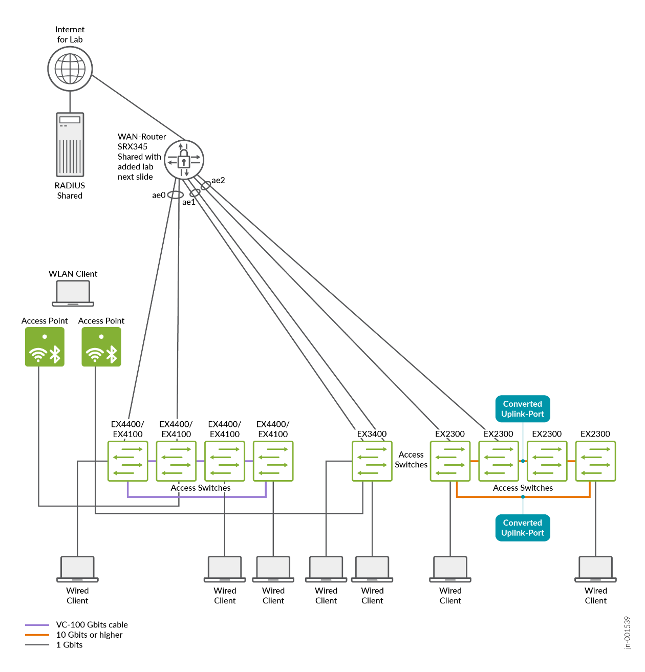
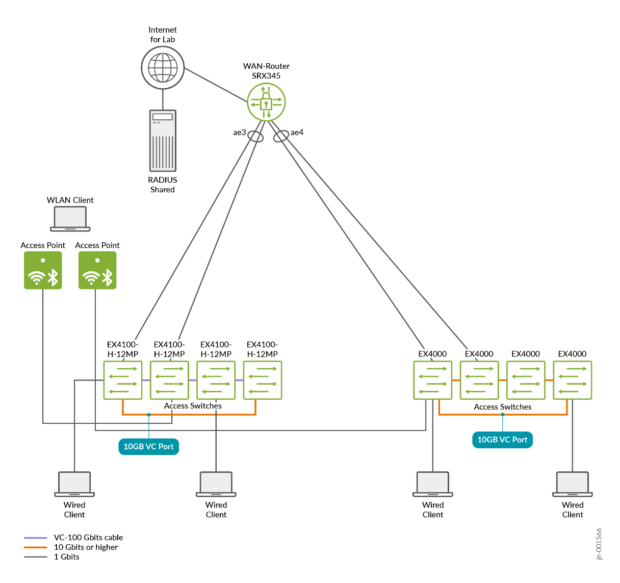
Figure 4: Test Bed without Distribution Layer Virtual
Chassis with Phase2 added devices
- A design where the standalone switch and all Virtual Chassis in the access layer are connected to a Virtual Chassis in the distribution layer. That distribution layer then has the final connection to the WAN router. This is usually suggested when a customer wants to deploy five or more Virtual Chassis in the access layer.
Figure 5: Test Bed with Distribution Layer Virtual
Chassis
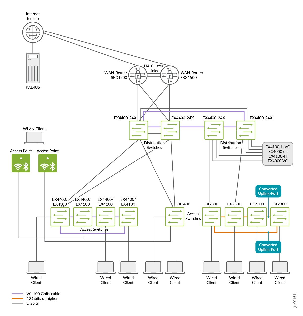
Figure 6: Test Bed with Distribution Layer Virtual
Chassis and added Phase2 access switches
Platforms / Devices Under Test (DUT)
Testing was performed with a focus on the EX Series Switches using the following Junos OS versions:
| Devices Under Test | ||
|---|---|---|
| Platform | Device | Junos OS Release |
| EX4400 (added in Phase2) | Access switch (standalone) | 24.4R2 |
| EX4100 | Access switch VC | 24.4R2 |
| EX2300 | Access switch VC | 24.4R2 |
| EX4400-24X | Distribution switch | 24.4R2 |
| EX3400 | Access switch (standalone) | 24.4R2 |
| EX4000 (added in Phase2) | Access switch VC | 24.4R2 |
| EX4100-H (added in Phase2) | Access switch VC | 24.4R2 |
| SRX345 | WAN router | 23.4R2-S5 |
| SRX1500 | WAN router | 23.4R2-S5 |
Test Bed Configuration
The appendix section of this document shares information on exactly how some of the tests were performed. Contact your Juniper account representative to obtain the full archive of the test bed configurations used for this JVD.