Use Case and Reference Architecture
The 5-stage Datacenter design is similar to the 3-stage datacenter design with the exception of a Super spine layer. This allows for scaling large scale datacenter design with requirements for large datastores and the compute nodes that need to connect to the data storage.
In rare cases, customers have deployed 5-stage design where datacenters are located closer together. This allows one Blueprint in Apstra to manage datacenters. This design can work in the above-mentioned scenario or in some cases where dark fiber is used as an interconnect. Paying close attention to performance and latency, it’s recommended that the 5-stage design should be used cautiously to interconnect datacenters. Please contact your Juniper account representative for more information.
This JVD document validates the 5-stage datacenter design where racks are located in the same lab location. The scaling and performance tests are based on this design.
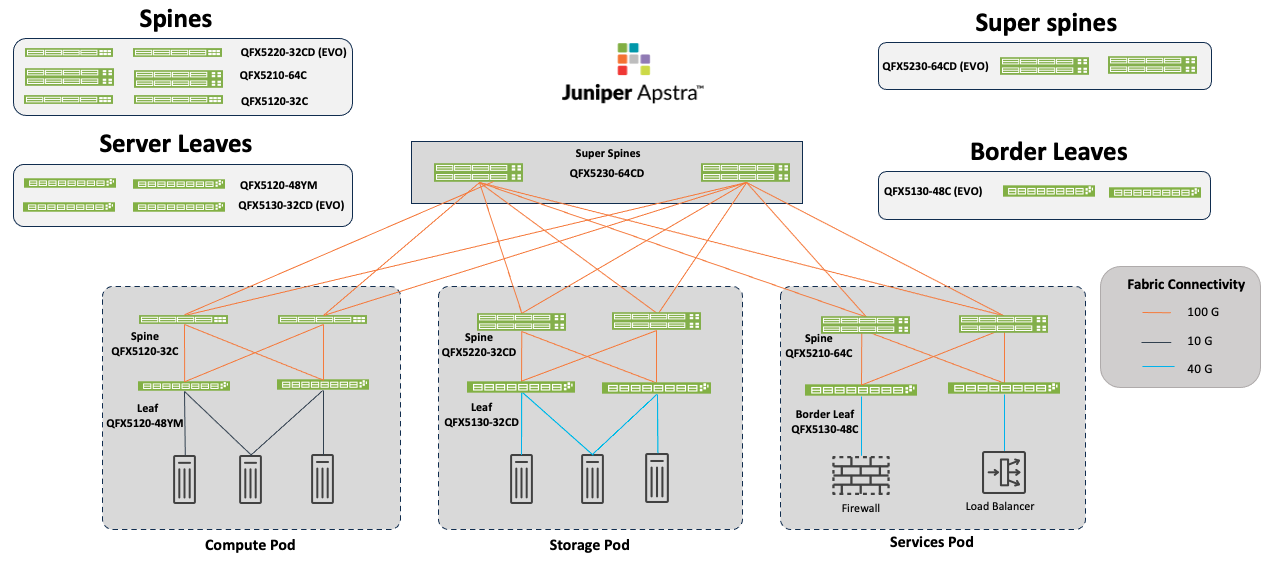
In the below Figure: 5-Stage Datacenter Architecture with Apstra, each Super spine is connected to each spine in a POD. Hence there can be multiple Pods connected to the Super spines. A POD consists of Spine and Leaf layers and is the equivalent of a 3-stage Fabric. The term 5-stage refers to the number of network devices that traffic sent from one host to another must traverse to reach its destination. For the purposes of brevity, there are only three pods shown. There can also be multiple Super spines depending on the amount of traffic and ports needed.