
Verification
Underlay Fabric Verification
To verify that the fabric is functional and the changes are configured, log into the console or CLI of each of the spine switches. From the shell of each of the spine switches, enter the following Junos OS CLI command:
show bgp summary | no-moreThe output of this command should resemble the Following output. It shows that BGP is established from each spine to each of the five leaf switches for loopback and fabric link IPv6 addresses.
From Spine1:
Threading mode: BGP I/O
Default eBGP mode: advertise - accept, receive - accept
Groups: 2 Peers: 10 Down peers: 0
Table          Tot Paths  Act Paths Suppressed    History Damp State    Pending
inet6.0
                      15         10          0          0          0          0
bgp.evpn.0
                     323        323          0          0          0          0
Peer                     AS      InPkt     OutPkt    OutQ   Flaps Last Up/Dwn State|#Active/Received/Accepted/Damped...
fdf6:ed70:1fac:f2d1::1       64514        100        102       0       0       43:19 Establ
  inet6.0: 2/3/3/0
fdf6:ed70:1fac:f2d1::3       64515         99        102       0       0       43:23 Establ
  inet6.0: 2/3/3/0
fdf6:ed70:1fac:f2d1::5       64516         95         95       0       0       41:07 Establ
  inet6.0: 2/3/3/0
fdf6:ed70:1fac:f2d1::7       64517         95         96       0       0       41:10 Establ
  inet6.0: 2/3/3/0
fdf6:ed70:1fac:f2d1::9       64518         96         98       0       0       41:50 Establ
  inet6.0: 2/3/3/0
fdf6:ed70:1fac:f2d1::1000       64514        100        290       0       0       43:18 Establ
  bgp.evpn.0: 4/4/4/0
fdf6:ed70:1fac:f2d1::1001       64515        100        289       0       0       43:16 Establ
  bgp.evpn.0: 4/4/4/0
fdf6:ed70:1fac:f2d1::1002       64516        158        221       0       0       40:48 Establ
  bgp.evpn.0: 106/106/106/0
fdf6:ed70:1fac:f2d1::1003       64517        158        222       0       0       40:56 Establ
  bgp.evpn.0: 106/106/106/0
fdf6:ed70:1fac:f2d1::1004       64518        158        226       0       0       41:48 Establ
  bgp.evpn.0: 103/103/103/0
From Spine2:
Threading mode: BGP I/O
Default eBGP mode: advertise - accept, receive - accept
Groups: 2 Peers: 10 Down peers: 0
Table          Tot Paths  Act Paths Suppressed    History Damp State    Pending
inet6.0
                      15         10          0          0          0          0
bgp.evpn.0
                     323        323          0          0          0          0
Peer                     AS      InPkt     OutPkt    OutQ   Flaps Last Up/Dwn State|#Active/Received/Accepted/Damped...
fdf6:ed70:1fac:f2d1::b       64514        101        103       0       0       44:03 Establ
  inet6.0: 2/3/3/0
fdf6:ed70:1fac:f2d1::d       64515        101        104       0       0       44:15 Establ
  inet6.0: 2/3/3/0
fdf6:ed70:1fac:f2d1::f       64516         97        103       0       0       41:57 Establ
  inet6.0: 2/3/3/0
fdf6:ed70:1fac:f2d1::11       64517         96         98       0       0       42:00 Establ
  inet6.0: 2/3/3/0
fdf6:ed70:1fac:f2d1::13       64518         98         99       0       0       42:46 Establ
  inet6.0: 2/3/3/0
fdf6:ed70:1fac:f2d1::1000       64514        102        291       0       0       43:53 Establ
  bgp.evpn.0: 4/4/4/0
fdf6:ed70:1fac:f2d1::1001       64515        102        292       0       0       44:05 Establ
  bgp.evpn.0: 4/4/4/0
fdf6:ed70:1fac:f2d1::1002       64516        160        224       0       0       41:49 Establ
  bgp.evpn.0: 106/106/106/0
fdf6:ed70:1fac:f2d1::1003       64517        160        223       0       0       41:53 Establ
  bgp.evpn.0: 106/106/106/0
fdf6:ed70:1fac:f2d1::1004       64518        159        227       0       0       42:37 Establ
  bgp.evpn.0: 103/103/103/0
If the output of the show bgp summary | no-more command resembles the screenshot above, a bare-bones network fabric is now complete. However, it is not yet ready for production use as the overlay network with VRFs, VLANs, and VNIs still must be applied.
If the output of the show bgp summary | no-more command does not resemble the output shown above, it is essential to remedy any configuration errors before proceeding further.
Overlay Verification
The steps to configure overlay network are same for IPv4 and IPv6 networks except the difference in IP addressing. In this validated design, only IPv6 overlay configuration is used as this validated design discusses only the IPv6 addressing. The steps to create the Virtual Network, Routing Zones are same across the two validated design. In section IPv6 Overlay with IPv6 underlay the overlay configuration is discussed and as suggested the overlay network uses EBGP protocol with IPv6 loopback address. In Apstra this will be configured after creating the Routing zone after which Apstra will prompt to configure the overlay network which requires the loopback IP address to be assigned by assigning the IPV6 address pool.
Configure Routing Zone for Red and Blue Tenants and Specify a Virtual Network Identifier
- From Blueprints → Staged → Virtual → Routing Zones.
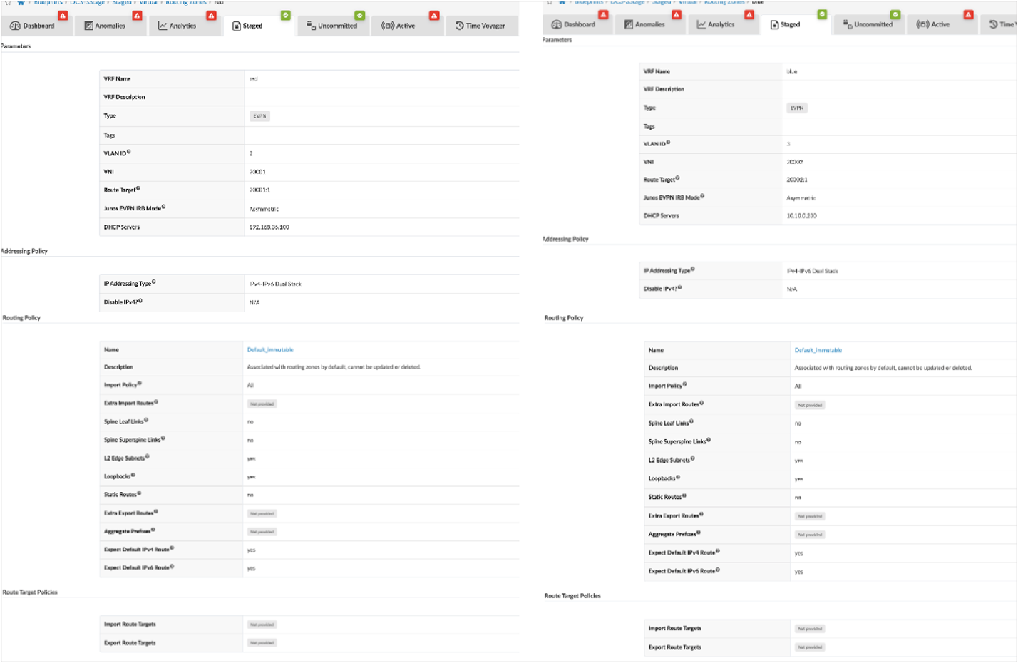
- Click Create Routing Zone and provide the following information:
- VRF Name: blue
- VLAN ID: 3
- VNI: 20002
- IP Addressing: IPv4-IPv6 Dual-Stack
- Routing Policies: Default immutable
- Symmetric IRB mode for Junos OS EVPN: Asymmetric
- Create another routing zone with the following information:
- VRF Name: red
- VLAN ID:2
- VNI: 20001
- IP Addressing: IPv4-IPv6 Dual-Stack
- Routing Policies: Default immutable
- Symmetric IRB mode for Junos OS EVPN: Asymmetric
Figure 18: Routing Zone for Red and Blue VRF with IPV6 Address Only
Assign EVPN Loopback Address for Overlay Network
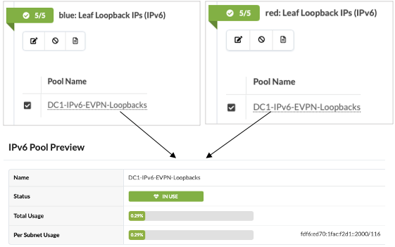
After creating the routing zones, assign the IPV6 loopback address by allocating the resource Pool in Apstra. Apstra assigns unique IPV6 address from the pool and automatically performs the administration function of assigning IP address and releasing IP address when the address is released.
Navigate to Blueprint → Staged → Routing Zone and assign resources from the right-hand side panel.
Figure 19: Assign IPV6 Address Pool in Apstra for Overlay Network
Create Virtual Networks in Red and Blue Routing Zones
Next create Virtual Networks. Virtual networks should be associated with routing zones (VRF). Create the virtual networks (VNIs) and associate these Virtual Networks with the routing zone (VRF) created earlier. Optionally, create any additional routing zones and virtual networks for production environments based on individual requirements.
Following are the networks created and assigned to appropriate leaf switches in the fabric. The input fields are as follows:
For Blue Network:
- Click Create Virtual Networks.
- Set type of network VXLAN.
- Provide name: blue_all_1400 and blue_all_1401.
- Select the Blue routing zone for both networks:
- Provide VNI:
- VLAN 1400 and VNI 11400 for blue_all_1400.
- VLAN 1401 and VNI 11401 for blue_all_1401.
- IPv4 Connectivity - Disabled. IPv6 connectivity – Enabled.
- Create Connectivity Template for: Tagged.
- Provide IPV4 Subnet and Virtual IP Gateway:
- 10.10.0.0/23, 10.10.0.1
- 10.10.2.0/23, 10.10.2.1
- Provide IPv6 Subnet and Virtual IP Gateway:
- 2001:db8:dc1:10:0a:00::/96, 2001:db8:dc1:10:0a:00::1 for blue_all_1400
- 2001:db8:dc1:10:0a:02::/96 , 2001:db8:dc1:10:0a:02::1 for blue_all_1401
- Assign to leaf switches.
For Red Network:
- Click Create Virtual Networks.
- Set type of network VXLAN.
- Provide name: red_all_400 and red_all_401.
- Select the Red routing zone for both networks:
- Provide VNI and VLAN:
- VLAN 400 and VNI 10400 for red_all_400
- VLAN 401 and VNI 10401 for red_all_401
- IPv4 Connectivity – Disabled. IPv6 connectivity – Enabled.
- Create Connectivity Template for: Tagged.
- Provide IPv6 Subnet and Virtual IP Gateway:
- 2001:db8:dc1:10:01:00::/96, 2001:db8:dc1:10:01:00::1 for red_all_400
- 2001:db8:dc1:10:01:01::/96, 2001:db8:dc1:10:01:01::1 for red_all_401
- Assign to leaf switches.
Figure 20: Red and Blue Virtual Networks with IPv6 IRB Subnet Assigned to Leaf Nodes
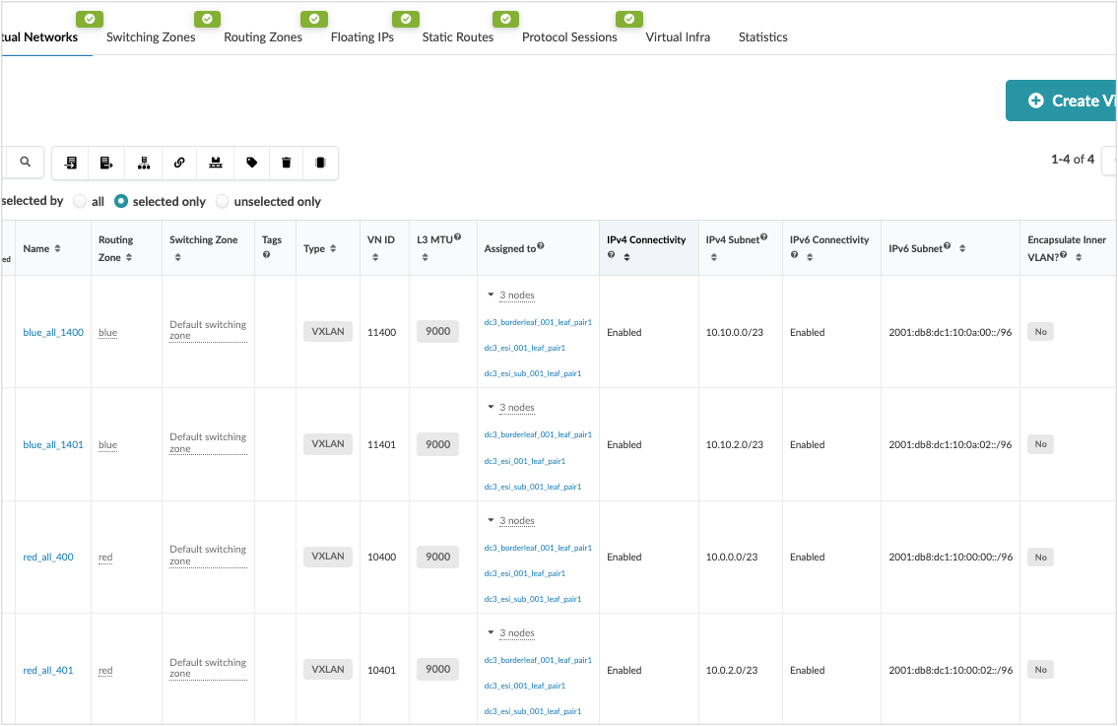
IRB Network is created, and a connectivity template is added and assigned to leaf switches. For more information on connectivity templates, see the Apstra Data Center Director User Guide.
While creating a virtual network, if the create connectivity template is selected above as tagged, Apstra creates a connectivity template, which is generated automatically for the virtual network.
Navigate to Blueprint → Staged → Connectivity Templates to view the templates and assign them to leaf switches. When assigned to leaf switches, a tagged aggregated ethernet interface is created connecting the servers. Then, navigate to Blueprint → Uncommitted to review the uncommitted changes and commit the overlay configuration. Alternatively, also review the configuration generated for each leaf switch to which the overlay network is created by navigating to Blueprint → Staged → Physical → Nodes and check the configuration.
Verify Overlay Connectivity for Blue and Red Network
After committing changes in the Apstra UI, these changes are now applied to the switches.
To begin verifying the fabric’s configuration, log on to the leaf switches. From the CLI of the leaf switches, enter the following commands:
!
//begin QFX leaf switch commands//
show interfaces irb terse
show vlans instance evpn-1 vn1400
show vlans instance evpn-1 vn1401
show vlans instance evpn-1 vn1201
show vlans instance evpn-1 vn1202
!
This output displays multiple IRB interfaces and the configured routing instances for the Blue and Red networks.
Red Network IRB on one of the leaf switches:
{master:0}
root@dc1-esi-001-leaf1> show interfaces irb.400 terse
Interface               Admin Link Proto    Local                 Remote
irb.400                 up    up   inet     10.0.0.1/23
                                   inet6    2001:db8:dc1:10::1/96
                                            fe80::96f7:ad01:906e:5740/64

{master:0}
root@dc1-esi-001-leaf1> show interfaces irb.401 terse
Interface               Admin Link Proto    Local                 Remote
irb.401                 up    up   inet     10.0.2.1/23
                                   inet6    2001:db8:dc1:10:0:2:0:1/96
                                            fe80::96f7:ad01:916e:5740/64
Blue Network IRB on one of the leaf switches:
{master:0}
root@dc1-esi-001-leaf1> show interfaces irb.1400 terse
Interface               Admin Link Proto    Local                 Remote
irb.1400                up    up   inet     10.10.0.1/23
                                   inet6    2001:db8:dc1:10:a::1/96
                                            fe80::96f7:ad05:786e:5740/64

{master:0}
root@dc1-esi-001-leaf1> show interfaces irb.1401 terse
Interface               Admin Link Proto    Local                 Remote
irb.1401                up    up   inet     10.10.2.1/23
                                   inet6    2001:db8:dc1:10:a:2:0:1/96
                                            fe80::96f7:ad05:796e:5740/64
Since Apstra, configures a MAC-VRF [routing-instance] called evpn-1 as VLAN-Aware routing mode, the same can be seen from the following command output for all the Red and Blue network VLANs.
{master:0}
root@dc1-esi-001-leaf1> show vlans instance evpn-1 vn1400

Routing instance        VLAN name             Tag          Interfaces
evpn-1                  vn1400                1400
                                                           ae1.0*
                                                           esi.4967*
                                                           esi.4981*
                                                           esi.7295*
                                                           esi.7523*
                                                           esi.7569*
                                                           esi.8160*
                                                           vtep-91.32770*
(…truncated)

{master:0}
root@dc1-esi-001-leaf1> show vlans instance evpn-1 vn1401

Routing instance        VLAN name             Tag          Interfaces
evpn-1                  vn1401                1401
                                                           ae1.0*
                                                           esi.4967*
                                                           esi.4981*
                                                           esi.7295*
                                                           esi.7523*
                                                           esi.8160*
                                                           vtep-91.32770*
(…truncated)

{master:0}
root@dc1-esi-001-leaf1> show vlans instance evpn-1 vn400

Routing instance        VLAN name             Tag          Interfaces
evpn-1                  vn400                 400
                                                           ae1.0*
                                                           esi.4967*
                                                           esi.4981*
                                                           esi.7295*
                                                           esi.7523*
                                                           esi.7569*
                                                           esi.8160*
                                                           vtep-91.32770*
(…truncated)

{master:0}
root@dc1-esi-001-leaf1> show vlans instance evpn-1 vn401

Routing instance        VLAN name             Tag          Interfaces
evpn-1                  vn401                 401
                                                           ae1.0*
                                                           esi.4967*
                                                           esi.4981*
                                                           esi.7295*
                                                           esi.7523*
                                                           esi.7569*
                                                           esi.8160*
                                                           vtep-91.32770*
(…truncated)
Verify that IRB is Configured on Leaf Switches
Within the CLI of the leaf switches, enter the following commands:
!
//begin QFX CLI commands//
show evpn database | match irb.40
show evpn database | match irb.140
!
The output of this command displays the distributed gateways on all switches.
The gateways display 10.0.0.1, 10.0.2.1 for the Red network, and 10.10.0.1, 10.10.2.1 for the Blue network. These IRB configurations apply only to devices assigned in the connectivity templates. No other fabric switches have this IRB configured unless assigned through the connectivity template.
{master:0}
root@dc1-esi-001-leaf1> show evpn database | match irb.40
     10400      02:90:69:00:00:01  irb.400                        Sep 18 09:03:30  10.0.0.1
     10401      02:90:69:00:00:01  irb.401                        Sep 18 09:03:30  10.0.2.1
{master:0}
root@dc1-esi-001-leaf1> show evpn database | match irb.140
11400 02:90:69:00:00:01 irb.1400 Sep 18 09:03:30 10.10.0.1
11401 02:90:69:00:00:01 irb.1401 Sep 18 09:03:30 10.10.2.1Verify the Leaf Switch Routing Table
Within the CLI of the leaf switches, enter the following commands:
!
//begin QFX CLI commands//
show route table red.inet6.0 2001:db8:dc1:10:00:00::/96
show route table red.inet6.0 2001:db8:dc1:10:00:02::/96
show route table blue.inet6.0 2001:db8:dc1:10:0a:00::/96
show route table blue.inet6.0 2001:db8:dc1:10:0a:02::/96
show route table red.inet.0 10.0.0.0/23
show route table red.inet.0 10.0.2.0/23
show route table blue.inet.0 10.10.0.0/23
show route table blue.inet.0 10.10.2.0/23
!
The output of this command displays the routes for the VRFs Red network for one of the leaf switches.
{master:0}
root@dc1-esi-001-leaf1> show route table red.inet6.0 2001:db8:dc1:10:00:00::/96

red.inet6.0: 2822 destinations, 6606 routes (2822 active, 0 holddown, 0 hidden)
Restart Complete
@ = Routing Use Only, # = Forwarding Use Only
+ = Active Route, - = Last Active, * = Both

2001:db8:dc1:10::/96
                   *[Direct/0] 02:39:03
                    >  via irb.400
                    [EVPN/170] 02:39:04
                       to fdf6:ed70:1fac:f2d1::4 via et-0/0/40.0
                    >  to fdf6:ed70:1fac:f2d1::20 via et-0/0/41.0
  (..truncated)
2001:db8:dc1:10::1/128
                   *[Local/0] 02:39:03
                       Local via irb.400
{master:0}
root@dc1-esi-001-leaf1> show route table red.inet6.0 2001:db8:dc1:10:00:02::/96
red.inet6.0: 2822 destinations, 6606 routes (2822 active, 0 holddown, 0 hidden)
Restart Complete
@ = Routing Use Only, # = Forwarding Use Only
+ = Active Route, - = Last Active, * = Both
2001:db8:dc1:10:0:2::/96
*[Direct/0] 02:53:03
> via irb.401
[EVPN/170] 02:53:04
to fdf6:ed70:1fac:f2d1::4 via et-0/0/40.0
> to fdf6:ed70:1fac:f2d1::20 via et-0/0/41.0
(..truncated)
2001:db8:dc1:10:0:2:0:1/128
*[Local/0] 02:53:03
Local via irb.401The output of this command displays the routes for the VRFs Blue network for one of the leaf switches.
{master:0}
root@dc1-esi-001-leaf1> show route table blue.inet6.0 2001:db8:dc1:10:0a:00::/96

blue.inet6.0: 2542 destinations, 6066 routes (2542 active, 0 holddown, 0 hidden)
Restart Complete
@ = Routing Use Only, # = Forwarding Use Only
+ = Active Route, - = Last Active, * = Both

2001:db8:dc1:10:a::/96
                   *[Direct/0] 02:54:18
                    >  via irb.1400
                    [EVPN/170] 02:54:19
                    >  to fdf6:ed70:1fac:f2d1::4 via et-0/0/40.0
                       to fdf6:ed70:1fac:f2d1::20 via et-0/0/41.0
(..truncated)
2001:db8:dc1:10:a::1/128
                   *[Local/0] 02:54:18
                       Local via irb.1400

{master:0}
root@dc1-esi-001-leaf1> show route table blue.inet6.0 2001:db8:dc1:10:0a:02::/96

blue.inet6.0: 2542 destinations, 6066 routes (2542 active, 0 holddown, 0 hidden)
Restart Complete
@ = Routing Use Only, # = Forwarding Use Only
+ = Active Route, - = Last Active, * = Both

2001:db8:dc1:10:a:2::/96
                   *[Direct/0] 02:55:38
                    >  via irb.1401
                    [EVPN/170] 02:55:39
                    >  to fdf6:ed70:1fac:f2d1::4 via et-0/0/40.0
                       to fdf6:ed70:1fac:f2d1::20 via et-0/0/41.0
(..truncated)
2001:db8:dc1:10:a:2:0:1/128
                   *[Local/0] 02:55:38
                       Local via irb.1401
The following command shows the ESI leaf switches overlay. It shows that the remote leaf VNIs are exchanged between the ESI leaf switches.
{master:0}
root@dc1-esi-001-leaf1> show ethernet-switching vxlan-tunnel-end-point remote
Logical System Name       Id  SVTEP-IP         IFL   L3-Idx    SVTEP-Mode    ELP-SVTEP-IP
<default>                 0   fdf6:ed70:1fac:f2d1::1002 lo0.0 0
 RVTEP-IP      IFL-Idx     Interface    NH-Id   RVTEP-Mode  ELP-IP        Flags
 fdf6:ed70:1fac:f2d1::1003 896 vtep.32770 2371  RNVE
 fdf6:ed70:1fac:f2d1::1004 895 vtep.32769 2370  RNVE
 RVTEP-IP         L2-RTT                   IFL-Idx   Interface    NH-Id   RVTEP-Mode  ELP-IP        Flags
 fdf6:ed70:1fac:f2d1::1003 evpn-1          671088642 vtep-11.32770 2371   RNVE
    VNID          MC-Group-IP
    11401         ::
    11400         ::
    10401         ::
    10400         ::
 RVTEP-IP         L2-RTT                   IFL-Idx   Interface    NH-Id   RVTEP-Mode  ELP-IP        Flags
 fdf6:ed70:1fac:f2d1::1004 evpn-1          671088641 vtep-11.32769 2370   RNVE
    VNID          MC-Group-IP
    11401         ::
    11400         ::
    10401         ::
    10400         ::
{master:0}
root@dc1-esi-001-leaf2> show ethernet-switching vxlan-tunnel-end-point remote
Logical System Name Id SVTEP-IP IFL L3-Idx SVTEP-Mode ELP-SVTEP-IP
<default> 0 fdf6:ed70:1fac:f2d1::1003 lo0.0 0
RVTEP-IP IFL-Idx Interface NH-Id RVTEP-Mode ELP-IP Flags
fdf6:ed70:1fac:f2d1::1002 896 vtep.32770 2673 RNVE
fdf6:ed70:1fac:f2d1::1004 895 vtep.32769 2550 RNVE
RVTEP-IP L2-RTT IFL-Idx Interface NH-Id RVTEP-Mode ELP-IP Flags
fdf6:ed70:1fac:f2d1::1002 evpn-1 671088642 vtep-11.32770 2673 RNVE
VNID MC-Group-IP
10401 ::
10400 ::
11401 ::
11400 ::
RVTEP-IP L2-RTT IFL-Idx Interface NH-Id RVTEP-Mode ELP-IP Flags
fdf6:ed70:1fac:f2d1::1004 evpn-1 671088641 vtep-11.32769 2550 RNVE
VNID MC-Group-IP
11401 ::
11400 ::
10401 ::
10400 ::{master:0}
root@dc1-single-001-leaf1> show ethernet-switching vxlan-tunnel-end-point remote
Logical System Name Id SVTEP-IP IFL L3-Idx SVTEP-Mode ELP-SVTEP-IP
<default> 0 fdf6:ed70:1fac:f2d1::1004 lo0.0 0
RVTEP-IP IFL-Idx Interface NH-Id RVTEP-Mode ELP-IP Flags
fdf6:ed70:1fac:f2d1::1002 886 vtep.32770 2669 RNVE
fdf6:ed70:1fac:f2d1::1003 885 vtep.32769 2545 RNVE
RVTEP-IP L2-RTT IFL-Idx Interface NH-Id RVTEP-Mode ELP-IP Flags
fdf6:ed70:1fac:f2d1::1002 evpn-1 671088642 vtep-11.32770 2669 RNVE
VNID MC-Group-IP
10401 ::
10400 ::
11401 ::
11400 ::
RVTEP-IP L2-RTT IFL-Idx Interface NH-Id RVTEP-Mode ELP-IP Flags
fdf6:ed70:1fac:f2d1::1003 evpn-1 671088641 vtep-11.32769 2545 RNVE
VNID MC-Group-IP
11401 ::
11400 ::
10401 ::
10400 ::