
Configuration Walkthrough
For the purposes of this validated design Apstra is used to provision 3-stage Fabric with IPV6 underlay. For this validated design, HPE Juniper Networking Switches and their supporting roles are suggested in this document in Table 1: Supporting Devices for 3-stage EVPN/VXLAN Fabric (ERB). For the purposes of this validated design, only the baseline devices are discussed in this walkthrough section.
This validated design is based on Apstra data center reference design which is a combination of rack types, templates, and blueprints. The steps are similar to that covered in the published 3-Stage EVPN/VXLAN Fabric with Juniper Apstra—Juniper Validated Design (validated design) which discusses the IPV4 underlay with EVPN-VXLAN Fabric.
For provisioning the devices into Apstra follow the 3-Stage IPv4 validated design for details on adding and managing devices, including applying Pristine configuration. The pristine configuration should be the base configuration or minimal configuration required to reach the devices with the addition of any users, include mgmt_junos VRF for maintaining management connectivity to devices, and so on. This creates a backup of the base configuration in Apstra and allows devices to be reverted to the pristine configuration in case of any issues.
Apstra Web UI: Onboard the Devices Into Apstra
There are two methods for adding HPE Juniper Networking devices into Apstra for management: manually or in bulk using ZTP. To add devices using ZTP, follow the ZTP steps described in Apstra Data Center Director User Guide.
Apstra Agent Profile
For the purposes of this validated design, the same username and password are used across all devices. Thus, only one Apstra Agent Profile is needed to onboard all the devices, making the process more efficient.
To create an Agent Profile, navigate to Devices → Agent Profiles and then click on Create Agent Profile**.
Apstra Onbox and Offbox Agents
Before adding devices into Apstra, the devices were preconfigured with a root password, a management-instance [edit system], management IP, and proper static routing if needed, as well as ssh Netconf, so that they can be accessed and configured by Apstra. For Junos OS based (not Junos OS Evolved) devices, offline agents are configured, which means the agent runs on the Apstra server. For instance, QFX5120-48YM. To add devices manually (recommended), in the Apstra user interface navigate to Devices → Agents → Create Offbox Agents.
For Junos OS Evolved based devices, onbox agents (agents are installed on the device) should be used to manage devices and telemetry. QFX5130-32CD, QFX5700 are some of these examples. To add devices manually (recommended), Apstra UI navigate to Devices → Agents → Create Onbox Agents.
Note: For the purposes of this validated design, IPV4 addresses were used to manage devices and the Apstra server was configured with IPV4 address. However from Apstra 6.1, IPv6 addresses can be used as management address for Apstra server as well as for devices to be managed. To enable IPv6 communication between Apstra server and devices issue the
sudo aos_magmt_ipv6 enablecommand on Apstra server to instruct Apstra software to use IPv6 for all process communication, see Apstra guide for more information.
Pristine Configuration
The minimum configuration required on devices to start device management is shown in the following. Netconf SSH is essential for Apstra communication with device. It is also mandatory to apply management VRF for Pristine configuration under [edit routing-instances mgmt_junos statement] (since Apstra 4.2 version) on all devices for enabling gRPC for telemetry gathering.
system {
    login {
        user aosadmin {
            uid 2000;
            class super-user;
            authentication {
                encrypted-password "xxxxx";
            }
        }
    }
    services {
        ssh;
        netconf {
            ssh;
        }
    }
    management-instance;
}
interfaces {
    em0 {
        unit 0 {
            family inet {
                address <address>/<cidr>;
            }
        }
    }
}
routing-instances {
    mgmt_junos {
        routing-options {
            static {
                route 0.0.0.0/0 next-hop <management-default-gateway>;
            }
        }
    }
}
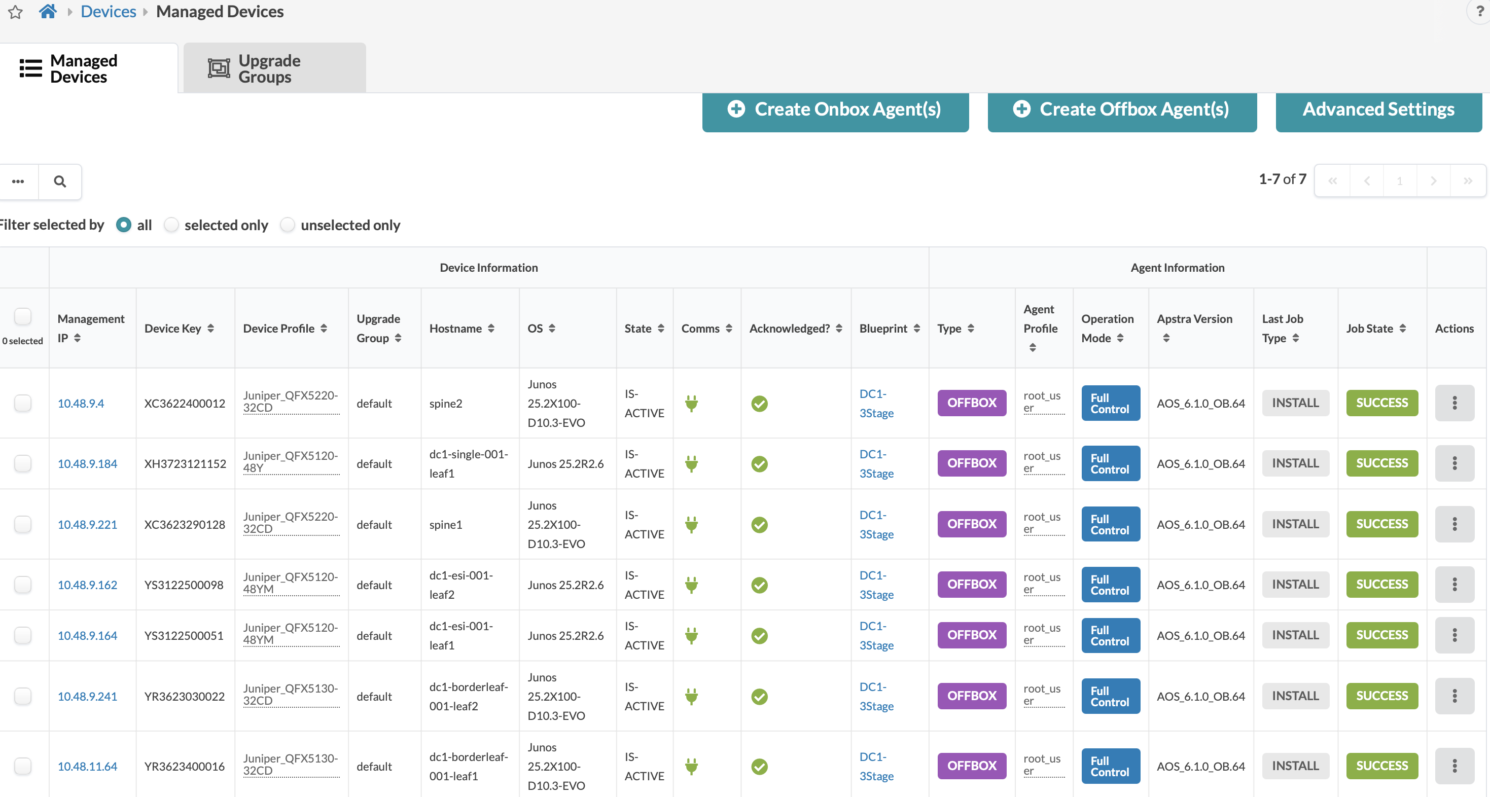
After devices are managed by Apstra, the next step is to acknowledge the device so as to assign the devices to blueprint, as shown in Figure 2: Apstra Acknowledged. A blueprint represents a data center in Apstra terminology.
Figure 2: Apstra Acknowledged
Apstra Web UI: Identify and Create Logical Devices and Interface Maps with Device Profiles
Apstra device lifecycle management describes the stages that a device configuration is in. Here are the highlevel configuration discussed to ensure these are in place or verified prior to creating a Blueprint.
For Apstra data center reference design following are provisioned in the order suggested:
- Determine logical devices for spine, leaf, and border leaf switches. Logical devices are abstractions of physical devices that specify common device form factors such as the amount, speed, and roles of ports. Vendor-specific information is not included, which permits building the network definition before selecting vendors and hardware device models. The Apstra software installation includes many predefined logical devices that can be used to create any variation of the logical device. Refer the 3-stage IPV4 validated design for more information on selecting or creating logical devices, interface maps and templates.
- Logical devices are then mapped to device profiles using interface maps. The ports mapped on the interface maps match the device profile and the physical device connections. Again, the Apstra software installation includes many predefined interface maps and device profiles.
- Finally, the racks and templates are defined using the configured logical devices and device profiles, which are then used to create a blueprint. In this validated design IPV6 solution is used for underlay and hence the template created for the blueprint will need to reflect the appropriate IPv6 selection.
Note: Device Profiles, Logical Devices, and Interface Maps are selected or can be custom created for each device role such as Spine, Server leaf, Border leaf. Generic devices are used to define systems or devices not managed by Apstra. Servers, external routers, firewalls etc are some of the devices that fall in this category and are connected to the Top Of Rack (TOR) switches. Generic devices can be External or Internal. External generic devices that are devices that do not form part of the Physical Rack in Data center. Internal Generic Devices are servers that are part of the rack and connect to the TOR switch.
Device Profiles
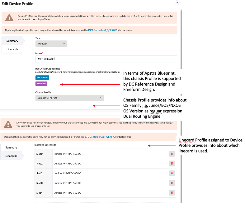
After a device is added successfully and managed by Apstra, depending on the Vendor, hardware model and type of device, Apstra automatically assigns a device profile to each device which are included by default when Apstra is installed. A device profile is depiction of device model that is qualified by Apstra which includes different port transformations/breakouts, speeds and panels. There are some devices which are chassis based (such as QFX5700) that are associated to chassis profile and linecard profile, see the following figure.
Figure 3: QFX5700 Design Profile
Logical Devices
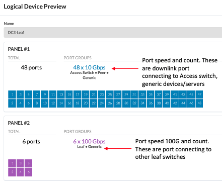
Apstra provides a ready set of logical devices which are logical representation of device that can be assigned to any of the roles such as Superspine, Spine, leaf, Access switch etc. It also specifies the count of ports, for example 32 port switch could have 16 ports of 100G and 16 ports of 10G, which can be assigned any of the roles that these ports are connected to. In some cases logical devices may need to be defined just in case none of the logical device profiles don’t match the actual device port count for speed.
Figure 4: Logical Devices for Collapsed Fabric Showing Port Speed and Connectivity
Interface Maps
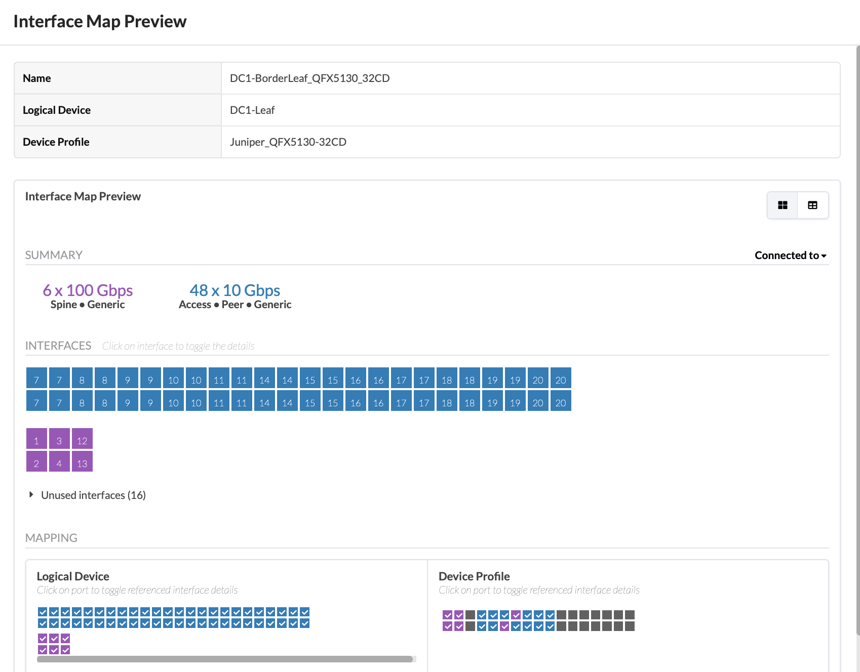
An Interface Map defines the relationship between logical ports and the actual physical ports on a device, as defined by their corresponding Device Profiles. Hence its necessary that the right ports are selected for corresponding port speed for each device profile that will be included in the Blueprint. Figure 5: Interface Map for device QFX5130-32CD showing which ports are configured shows the appropriate speed, transformation, for instance a 400G port can be broken into four 100G/25G/10G, increasing the total number of ports.
Figure 5: Interface Map for Device QFX5130-32CD Showing which Ports are Configured
Apstra Web UI: Racks, Templates, and Blueprints
Racks
After defining the logical devices and Interface maps, the next step is to create racks to place the logical devices in rack formation (for example, TOR, server leaves, and so on). The default design for this solution is two spines, five server leaf switches, and two border leaf switches. Any rack design can be created and used any number of times, so long as the spine switches have enough ports to support it.
In Apstra, create racks under Design → Rack Types. For this solution, there are four racks. One rack for border leaf switches and three racks for server leaf switches. For more information on creating racks, see Apstra Data Center Director User Guide.
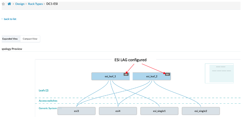
One of the important task of creating Rack design is to assign the uplinks from Leaf to Spine and downlinks to servers. In case of the downlinks from Leaf switch towards to the servers Ethernet Switch Identifier (ESI) Link Aggregation group (LAG) can be configured to provide redundant links. Apstra makes it easier to visualize and enable ESI Lag links in a rack.
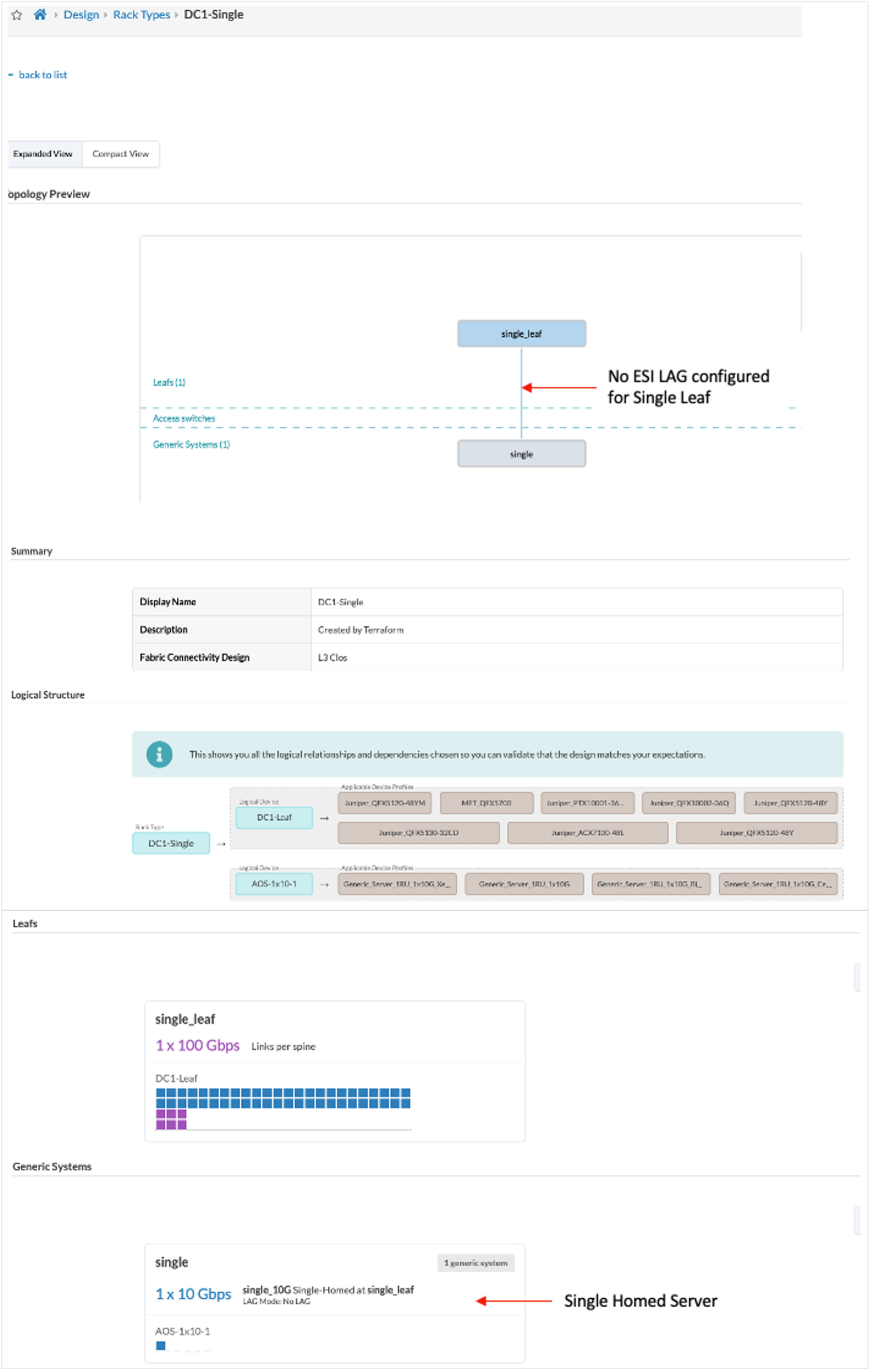
Following is an example of a leaf switch rack which is defined as Single Leaf as the option for Redundancy Protocol was selected as None while creating this Rack, instead of ESI.
Figure 6: Single Leaf Rack Design Options
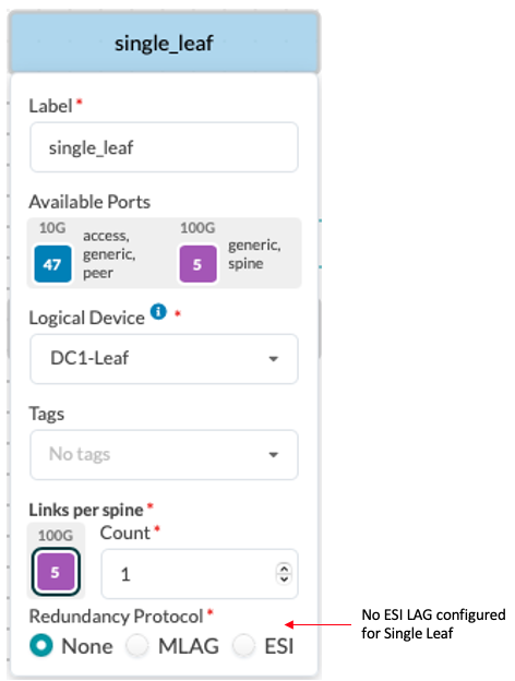
Figure 7: Single Leaf Rack
For an ESI enabled rack design, as shown in Figure 8: ESI LAG enabled on ESI Leaf Rack design ESI lag is configured towards servers and that is shown on the Leaf devices.
Figure 8: ESI LAG Enabled on ESI Leaf Rack Design
Templates
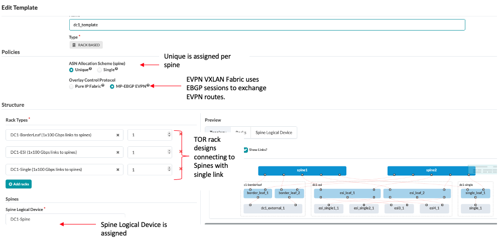
Templates define the structure and the intent of the network. After creating the racks, the spine links need to be connected to each of the racks. In this design, the rack-based templates are used to define the racks to connect as top-of-rack (ToR) switches (or pairs of ToR switches).
The uplinks between Spine and Leaf is 100G links. The spine logical device is assigned in the template. Since there are no super spines in this design, this is left out of the templates.
Figure 9: Templates for 3-stage Rack Based Design
Blueprint
Each blueprint represents a data center. Templates are created under the Design → Templates section and will be available in the global catalog for the blueprints. Once the template is defined, it can be used to create a blueprint for the data center.
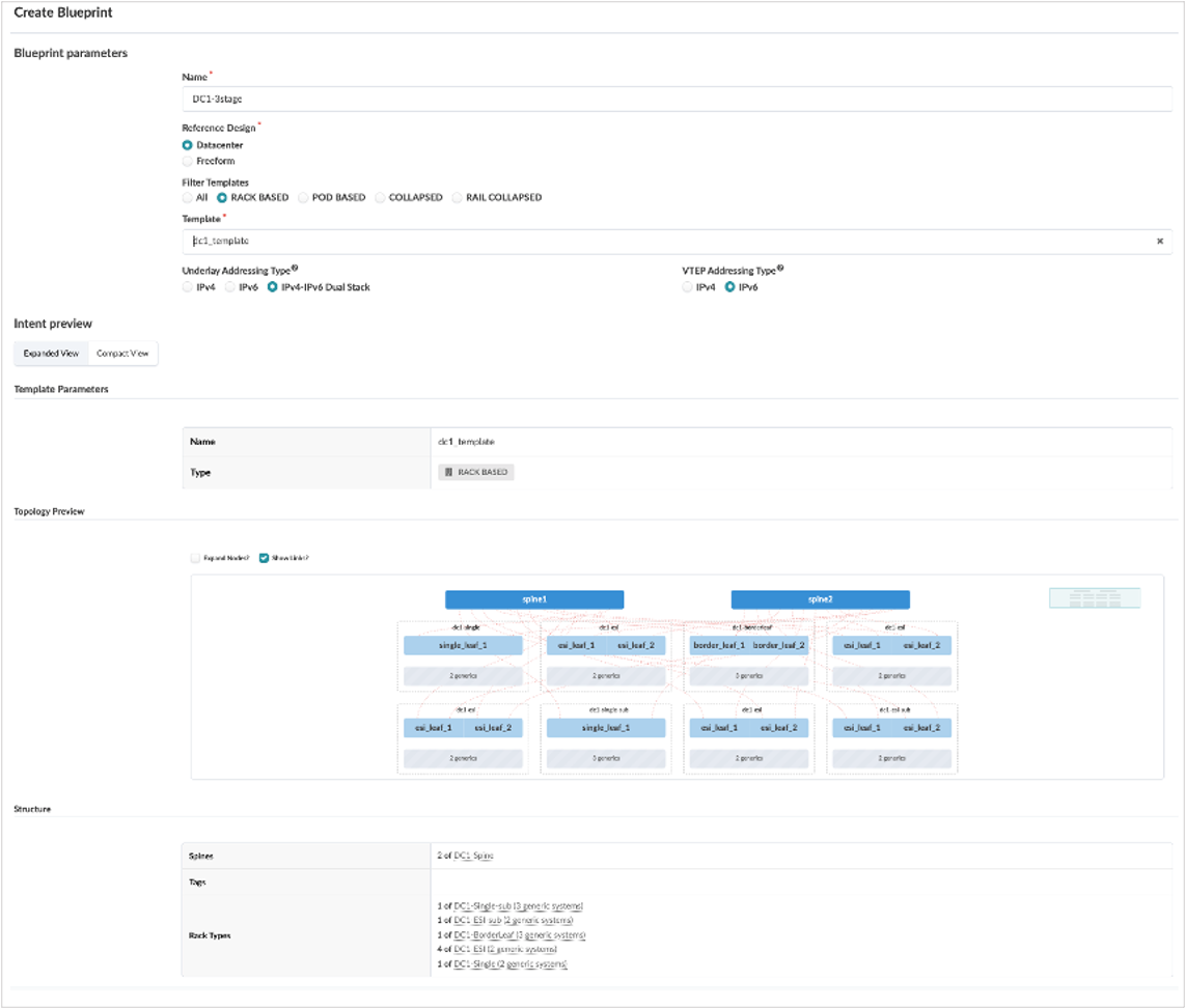
To create a blueprint, click on Blueprints → Create Blueprint. In the following screenshot the Blueprint is created using the template. It is recommended to select ‘Underlay Addressing Type’ to be IPv4-IPv6 Dual Stack.
Figure 10: Create Blueprint with IPv6
Apstra Web UI: Provisioning and Defining the Network
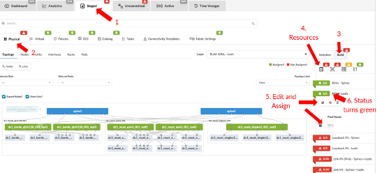
Once the blueprint is created, it means that the blueprint is ready to be staged. Review the tabs under the blueprint created. To start provisioning, click on the Staged tab → Physical and then click Build from the right-hand side panel.
Figure 11: Blueprint Assign Resources Under Build
Assign Resources: ASN IP Addresses
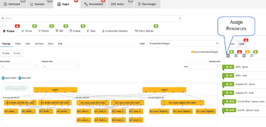
For building data center fabric, first step is to assign and IP addresses. A unique ASN is allocated to each switch in the Fabric. ASN for generic servers is optional. IPV6 address pool is assigned to Fabric IP links and loopback address.
Note: As IPv4 addressing is required for switch identification during EBGP session, assign IPV4 address pool in Apstra as the loopback address for each leaf switch, see the Junos OS configuration section Router-IDs for EBGP session.
For more information on assigning ASN and IP addressess, see Apstra Data Center Director User Guide.
Figure 12: ASN and IP Address Assigned
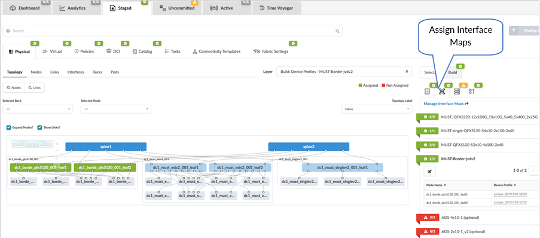
Assign Interface Maps to Switch Device Profile
From the blueprint, navigate to Staged → Physical → Build → Device Profiles. Next, assign devices to interface maps created in the section Interface maps with Device Profiles of this document.Note: The assignment of interface maps to generic systems or servers is optional. The status of these parameters will be marked RED and they are also marked as optional.
Figure 13: Blueprint Assign Interface Maps in Device Profiles Under Build
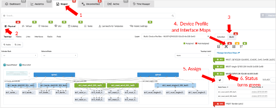
Figure 14: Interface Maps Assigned
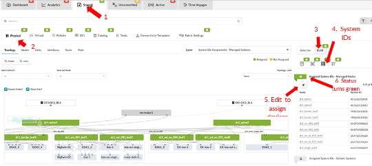
Assign the System IDs and the Correct Management IPs
From the blueprint, navigate to Staged → Physical → Build → Devices and click on Assigned System IDs. The system IDs are the devices serial numbers.
Figure 15: Blueprint Staged Assign System IDs Under Build
[]
Note: The device hostname and the display name (on Apstra) for each node or device is different these can be changed using Apstra.
No system IDs are assigned to generic servers and external routers, as these are not managed by Apstra.
Ensure all the devices are added to Apstra under Devices → Managed Devices before assigning system IDs (serial numbers of the devices).
Review Cabling
Apstra automatically assigns cabling ports on devices that may not be the same as physical cabling. However, the cabling assigned by Apstra can be overridden and changed to depict the actual cabling. This can be achieved by accessing the blueprint, navigating to Staged > Physical → Links and clicking the Edit Cabling Map button. For more information, see Apstra Data Center Director User Guide.
Apstra Fabric Policy Setting
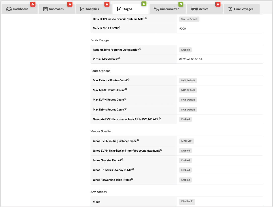
In Apstra its important to ensure the Fabric Policy settings are setup as intended for each fabric.
Figure 16: Apstra Fabric Policy Settings
Note: Any changes to the Fabric Policy settings should be performed under appropriate maintenance Window to avoid any issues.
The following settings should be set up for Fabric to function efficiently:
MTU Settings—The Fabric MTU setting can be consistently configured across the Fabric. Ensure that the MTU of the server→leaf links does not exceed the MTU of the leaf→spine links considering the extra overhead of the VXLAN encapsulation. A higher MTU is configured on the physical interface so as to account for VXLAN encapsulation. As seen from Figure 16: Apstra Fabric Policy Settings the Fabric MTU i.e. leaf to spine link is set to 9170 where as the Default SVI L3 MTU is set (lower than 9170) to 9000.
Apstra will detect this issue on the Blueprint → Uncommitted tab and throw an error if the Default SVI L3 MTU is same or higher than Fabric MTU, see the following.
Figure 17: Apstra Error for MTU Lower on Fabric Links to SVI L3 Links

- MAC-VRF—The Vendor-Specific setting Junos EVPN routing instance mode is set to MAC-VRF by default for all new blueprints that are created post Apstra version 4.2.
For any blueprint created prior to Apstra 4.2, the ‘default switch’ instance on Junos OS switches is allowed post upgrade of Apstra. However, it is recommended to set this option to MAC-VRF so as to normalize the configuration in a mixed setup of Junos OS and Junos OS Evolved. A VLAN-aware routing instance ‘evpn-1’ for MAC-VRF is created for Junos OS devices. This option doesn’t affect Junos OS Evolved devices as Junos OS Evolved can only support MAC-VRF by default. Starting from Apstra 6.2, multiple MAC-VRF is also supported with both VLAN-aware and VLAN-bundle to support Service Providers.
Note: If the blueprint is live and running in a production network, it is recommended to perform the above setting changes to MAC-VRF routing instance mode during a maintenance window as it is disruptive and requires a ‘reboot’ of Junos OS leaf switches, in this case the QFX5120s.
- Junos EVPN Next-hop and Interface count maximums For QFX5120, the default value of the next-hop table is 8K, and the default interface-num value is 4K which is low and can get exhausted and cause connectivity or performance issues.
The next-hop parameter indicates the number of next-hops to be used in the VXLAN overlay and underlay networks. The maximum number of entries is 48K (49152), shared between both overlay and underlay. The interface-num parameter indicates the maximum number of physical interfaces for use in either an underlay network or an EVPN-VXLAN overlay network. The maximum count here is 12K (12288), which is again shared between the overlay and underlay networks. When interface-num is exhausted, no new IRB interfaces and no new routing instances can be created. Hence the Vendor specific setting of Junos EVPN Max Next-Hop and Interface number is enabled by default. To simulate moderate traffic in datacenter, traffic scale testing was performed on devices to test the limits of Next-hop suggested in Table 1: Supporting Devices for 3-stage EVPN/VXLAN Fabric (ERB), see 3-stage test report for more information on scale numbers.
Note: If the Blueprint is live and running production network, it is recommended to perform the above setting during a maintenance window as it is disruptive.
forwarding-options {
    vxlan-routing {
        next-hop 45056;
        interface-num 8192;
        overlay-ecmp;
    }
    evpn-vxlan {
        shared-tunnels;
    }
}
- Junos EX-Series Overlay ECMP For EX4100/EX4400 switches which are used as access switches, this setting is ‘Enabled’. The EX switches though are used as access switches do handle the EVPN traffic. Hence enabling this option adds the following lines of configuration on EX switches.
forwarding-options {
    vxlan-routing {
        overlay-ecmp;
    }
    evpn-vxlan {
        shared-tunnels;
    }
}
Note: If the Blueprint is live and running production network, it is recommended to perform the above setting during a maintenance window as it is disruptive.
- Route option ‘Generate EVPN host routes from ARP/IPV6 ND ARP’ is Enabled so as to allow all EVPN vteps (leaf switches) in the fabric to redistribute ARP/IPV6 ND (when possible on NOS type) as EVPN type 5 /32 routes in the routing table. This option is applicable to only HPE Juniper Networking switches.
- Vendor Specific setting “Junos Forwarding Table Profile” is ‘Enabled’ for QFX5130/QFX5700 to set Unified Forwarding Table (UFT) profile ‘host-profile’ that allocates different amounts of memory for Layer 2 or Layer 3 entries depending on network. See section Forwarding Table Memory Allocation with the Unified Forwarding Table
Note: For QF5140-24CD, the ‘host-profile’ UFT profile was applied using configlet. If the Blueprint is live and running production network, it is recommended to perform the above setting during a maintenance window as it is disruptive.
- ‘Junos Graceful Restart’ is vendor-specific setting and needs to be ’Enabled’on all Junos OS devices. Apstra applies the following configuration:
routing-options {
    graceful-restart;
}
Note: If the Blueprint is live and running production network, it is recommended to perform the above setting during a maintenance window as it is disruptive.
- ‘Junos Graceful Restart’ is vendor-specific setting and needs to be ’Enabled’on all Junos OS devices. Apstra applies the following configuration: