Validation Framework
Extensive testing of best practice architectures is key to the Juniper Validated Design (JVD) program. JVDs qualify and quantify these best practice architectures, providing customers knowledge about the products and how solution can be deployed.
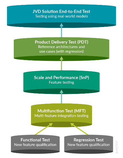
JVDE document is an extension of the core JVD document. Like the Juniper Validated Design document, JVDEs employ a layered testing approach to deliver reliability and repeatability. Individual features receive functional testing. Multifunction testing builds on this functional testing to see if multiple features work together. Product delivery testing builds upon multifunctional testing to validate that these features combined perform as expected for tested use cases, and JVD testing builds upon product delivery testing by testing multiple products together (including third-party integrations where appropriate) to ensure that all these products combined make an industry-leading solution.
Testing with real-world applications and traffic provides more accurate data regarding performance and response to different configurations. The standardized nature of JVDs ensures the same network architecture is deployed in multiple testing environments, and the use of JVDs by multiple customers allows for any lessons learned in production deployments to rapidly benefit all JVD customers. The more JVDs that are deployed worldwide, the greater the value they provide to all.
Test Bed
The test bed environment consists of two 3-stage fabric data center, 1 collapsed fabric and a 5-stage fabric data centers so as to covers different data center interconnect designs and hardware for border leaves.
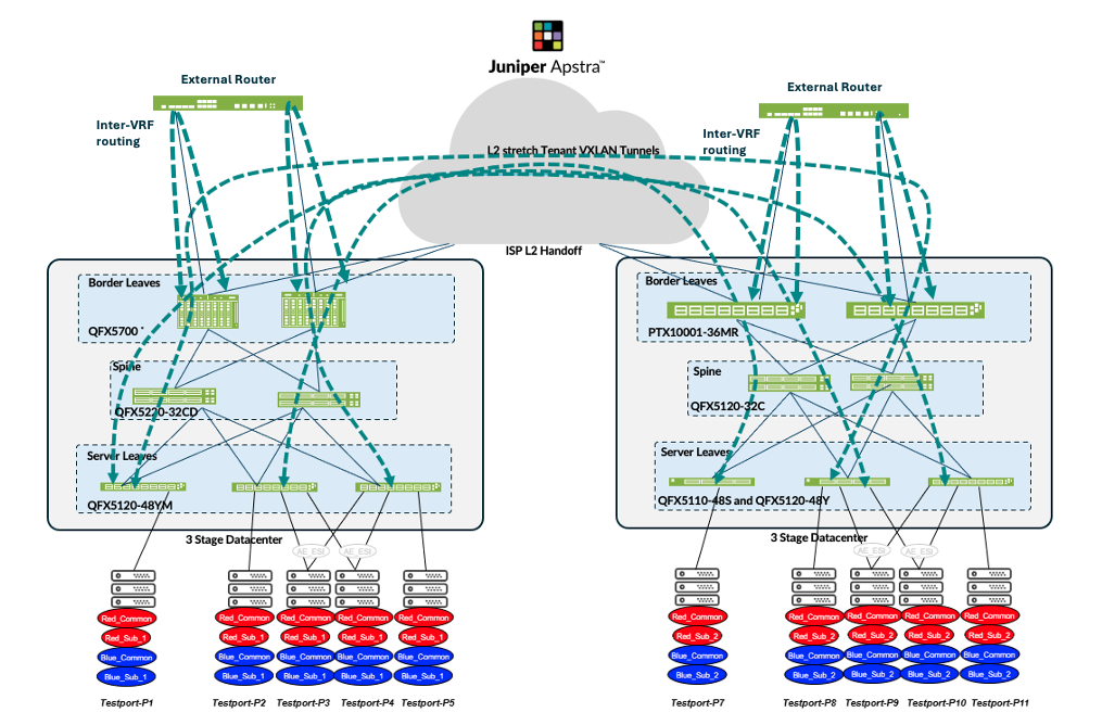
Over the top (OTT) Test Bed
The test bed design uses two 3-stage Fabric pre-configured in Apstra as Blueprints. The two data centers were used to interconnect the two fabrics using DCI feature in Apstra. In DC1, two QFX5700 are the border leaf switches and in DC2 two PTX10001-36MR were used as border leaf switches. The two DCs were connected using Interconnect switches, for the purposes of this lab QFX10002-36Q were used. A traffic generator (IXIA) is connected to the test ports connected to the leaves.
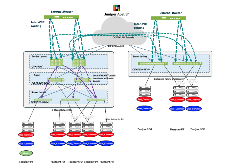
EVPN-VXLAN Type 2 Seamless stitching (with MACSEC)
For the purposes of this lab design, a 3-stage and a collapsed fabric design were pre-configured in Apstra as blueprints. The two data centers were used to interconnect the two fabrics using DCI feature in Apstra. In DC1, two QFX5700 are the border leaf switches and in DC3 two QFX5120-48YM were used as collapsed leaf switches. The two DCs were connected using Interconnect switches, for the purposes of this lab QFX10002-36Q were used. A traffic generator (IXIA) is connected to the test ports connected to the leaves in each pod.
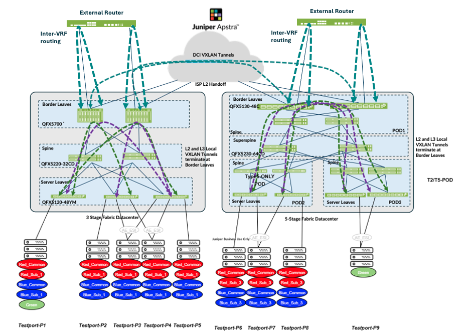
EVPN-VXLAN Type 2 and Type 5 Seamless stitching
For the purposes of this lab design, a 3-stage and a 5-stage fabric design were pre-configured in Apstra as blueprints. The two data centers were used to interconnect the two fabrics using DCI feature in Apstra. In DC1, two QFX5700 are the border leaf switches and in DC4 two QFX5130-48C were used as border leaf switches. The two DCs were connected using Interconnect switches, for the purposes of this lab QFX10002-36Q were used. A traffic generator (IXIA) is connected to the test ports connected to the leaves in each pod.
| VLAN GROUP | VLAN Ranges | Subnet IPv4 | Subnet IPv6 | Description |
|---|---|---|---|---|
| RED_COMMON | 400-599 | 10.0.[0-199].0/24 | 2001:db8:dc1:10:0:[0-c7]::/9 | Common range to hosts in both DC sites, linked to RED V |
| RED_SUB_DC1 | 600-799 | 10.1.[0-199].0/24 | 2001:db8:dc1:10:1:[0-c7]::/9 | Unique VLAN ranges in DC1, linked to RED VRF |
| RED_SUB_DC2 | 800-999 | 10.2.[0-199].0/24 | 2001:db8:dc1:10:2:[0-c7]::/9 | Unique VLAN ranges in DC2, linked to RED VRF |
| RED_SUB_DC4 | 1200-1399 | 10.4.[0-199].0/24 | 2001:db8:dc1:10:4:[0-c7]::/9 | Unique VLAN ranges in DC4, linked to RED VRF |
| BLUE_COMMON | 1400-1599 | 10.10.[0-199]/024 | 2001:db8:dc1:10:a:[0-c7]::/9 | Common range to hosts in both DC sites, linked to BLUE |
| BLUE_SUB_DC1 | 1600-1799 | 10.11.[0-199]/024 | 2001:db8:dc1:10:b:[0-c7]::/9 | Unique VLAN ranges in DC1, linked to BLUE VRF |
| BLUE_SUB_DC2 | 1800-1999 | 10.12.[0-199]/024 | 2001:db8:dc1:10:c:[0-c7]::/9 | Unique VLAN ranges in DC2, linked to BLUE VRF |
| BLUE_SUB_DC4 | 2200-2399 | 10.14.[0-199]/024 | 2001:db8:dc1:10:e:[0-c7]::/9 | Unique VLAN ranges in DC4, linked to BLUE VRF |
| GREEEN_SUB_DC1 | 2700-2899 | 10.27.0.0/24 | 2001:db8:dc1:10:1b:[0-c7]::/ | Unique VLAN ranges per site, linked to GREEN (Type 5 ON |
| GREEEN_SUB_DC4 | 2500-2699 | 10.25.0.0/24 | 2001:db8:dc1:10:19:[0-c7]::/ | Unique VLAN ranges per site, linked to GREEN (Type 5 ON |
All of the above test beds were mutually exclusive and were configured separately to test the three DCI designs. VLAN and Subnets above in Table 1 were used to configure the test ports using IXIA.
Platforms / Devices Under Test (DUT)
| Platforms and Roles | ||||
|---|---|---|---|---|
| Solution | Server Leaf Switches | Border Leaf Switches | Spine | Super Spine |
| 3-stage EVPN/VXLAN Data Center design (ERB) | QFX5120-48Y-8C | QFX5700 (EVO) | QFX5220-32CD (EVO) | |
| QFX5110-48S | PTX10001-36MR | QFX5120-32C | ||
| Collapsed Fabric Data Center design | QFX5120-48YM | |||
| 5-stage EVPN/VXLAN Data Center design (ERB) | QFX5120-48YM | QFX5130-48C (EVO) | QFX5220-32CD (EVO) | QFX5230-64CD (EVO) |
| QFX5130-32CD (EVO) | QFX5210-64C | |||
| QFX5120-32C | ||||
| Part number | Optics Name | Device Role | Device Model |
|---|---|---|---|
| 740-067442 | QSFP+ 40GBase-SR4 | Border Leaf | QFX5700 |
| 740-067443 | QSFP+-40G-SR4 | Border Leaf | QFX5700 |
| 740-054053 | QSFP+-4X10G-SR | Border Leaf | PTX10001-36MR |
| Part number | Optics Name | Device Role | Device Model |
|---|---|---|---|
| 740-067442 | QSFP+ 40GBase-SR4 | Border Leaf | QFX5700 |
| 740-067443 | QSFP+-40G-SR4 | Border Leaf | QFX5700 |
| 740-031980 | SFP+-10G-SR | Collapsed Fabric Leaf | QFX5120-48YM |
| Part number | Optics Name | Device Role | Device Model |
|---|---|---|---|
| 740-067442 | QSFP+ 40GBase-SR4 | Border Leaf | QFX5700 |
| 740-067443 | QSFP+-40G-SR4 | Border Leaf | QFX5700 |
| 740-030658 | SFP+-10G-USR | Border Leaf | QFX5130-48C |
| 740-021308 | SFP+-10G-SR | Border Leaf | QFX5130-48C |
Test Bed Configuration
Contact your Juniper representative to obtain the full archive of the test bed configuration used for this JVD.