Configuration Walkthrough
This walkthrough summarizes the steps required to configure the Data Center Interconnectivity using Juniper Apstra.
As discussed in Use Case and Reference Architecture, this JVD will only cover three DCI use cases using different fabric design and Juniper Devices. This JVD will also include Media Access Control security (MACSEC) between DCI, however the configuration is provisioned as configlet as Apstra 5.0 is unable to support.
Prerequisite
Provision the 3-stage Data Center, Collapsed Fabric Data Center and 5-stage EVPN VXLAN Data Center as has been discussed in the respective data center design JVD.
Over-the-Top Design (with MACSEC)
For the DCI OTT design, two 3-stage data centers are interconnected using Layer 2 switches (QFX10002-36Q) or any ISP switches that support Layer 2 switching cross connect configuration as shown in below diagram. For QFX10002-36Q switches, licenses are needed for MPLS and L2-circuit. For more information on Layer 2 switching cross connect refer Juniper guide on Layer 2 circuit cross-connect (CCC) configuration. This JVD will briefly cover the configuration on these two switches as this can vary for different DCI implementation and hence is outside the scope of this JVD.
For the sake of clarity, the two data centers are referred to as DC1 and DC2 as shown below in Figure 1.
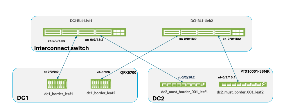
Ensure to physically cable the border leaf switches in both data centers as shown in Figure 1 to the Interconnect (ISP) switches, before proceeding to configure DCI in Apstra. To provision Data Center Interconnectivity using Apstra, here are the steps.
- Logon to Apstra UI and navigate to the blueprint of the first
3-stage data center (hereinafter referred to as DC1). Configure the
links to the Interconnect ISP switches as shown below for both
border leaves. Ensure the cabling is also updated reflecting the
interface connecting the ISP switches on each of the border leaves.
For more information on creating an external generic server refer
the Apstra
guide for adding links to existing Blueprint.
Figure 2: Links from Border Leaves to ISP Switch 1
 Figure 3: Border Leaf 2 Connectivity with ISP Switch 2
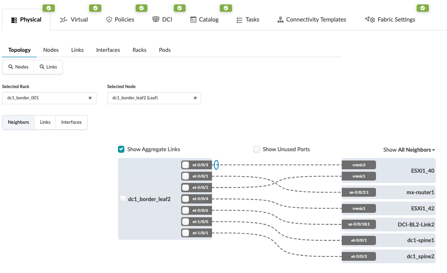
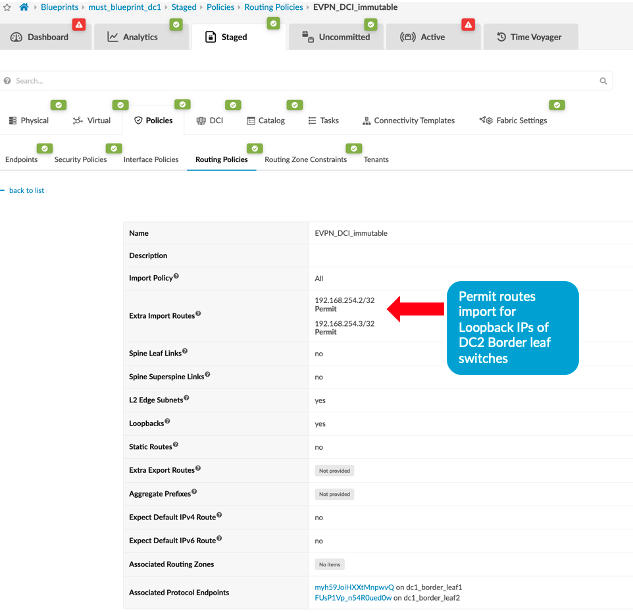
- Create the routing policy to allow the loopback IP of the
border leaf switches of remote data center, in this case DC2.
Navigate to Blueprint > Staged > Policies >
Routing Policies and create or modify the relevant policy
to permit the import routes of Loopback IPs of data center (DC2)
border leaf switches.
Figure 4: Add Import Routes for DC2 Border Leaf Switches
- Next create Connectivity Templates to connect border leaf
switches in current blueprint (DC1) to remote data center blueprint
(DC2). This step creates the underlay connectivity between the two
data centers which is VLAN tagged. The routing policy defined in
previous step is assigned for routes import. An underlay eBGP is
also created between the Border leaf switch1 of both data centers.
Similarly configure the underlay connectivity, eBGP between the
Border Leaf switch2 of both data centers. There should be two
connectivity templates created for each border leaf connectivity.
See Figure 1 to review the
connectivity.
Figure 5: Border Leaf Switch1 Connectivity Template
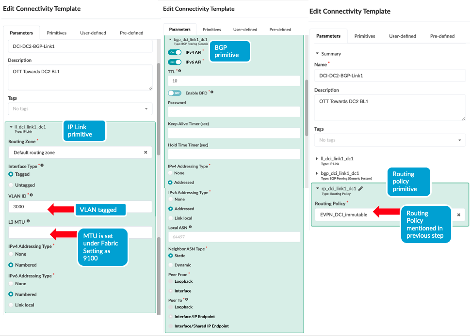 Figure 6: Border Leaf Switch2 Connectivity Template
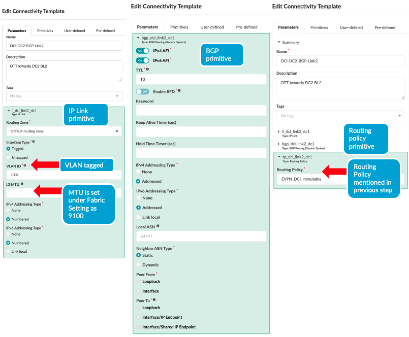
Once the Connectivity templates are created, assign them to the border leaf switches as shown below. For more information on Apstra connectivity templates, refer Juniper Apstra Guide.
Figure 7: Assign Connectivity Template to Border Leaf Switch1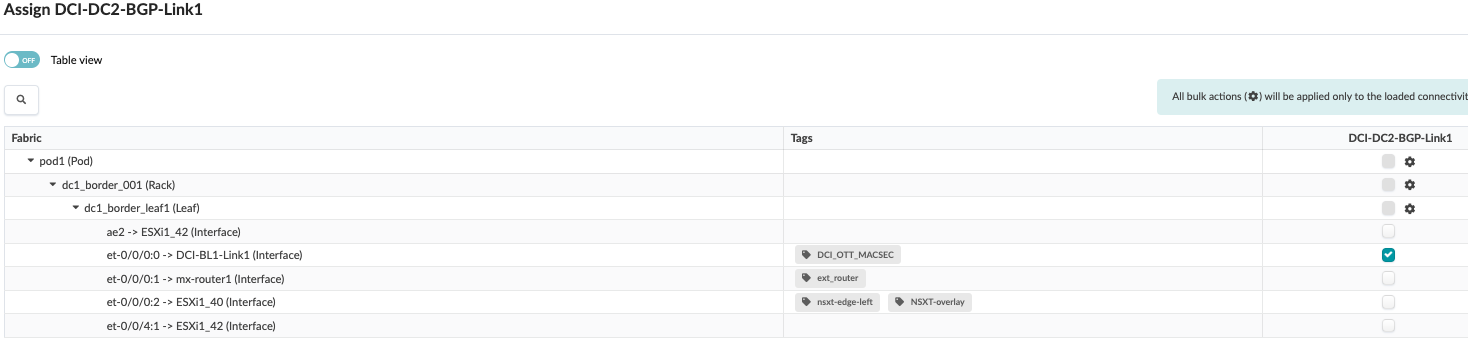 Figure 8: Assign Connectivity Template to Border Leaf Switch 2
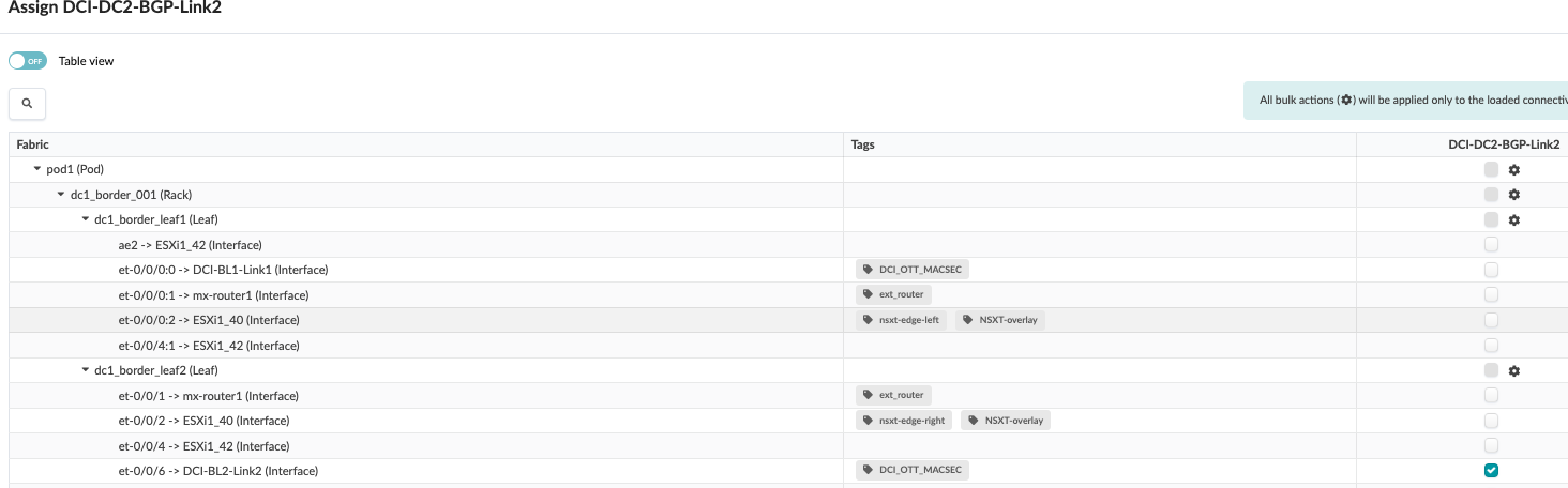
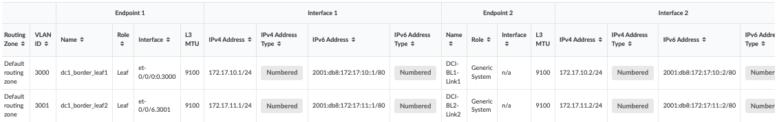
- After assigning the connectivity template, navigate to
Blueprint > Staged > Virtual > Routing
zone and click on the default routing zone to allocate
IPV4 and IPV6 IP addresses to create the border leaf connectivity
between the two data centers.
Figure 9: Assign IP Addresses to Create IP Link between Border Leaf Switches of Both Data Centers
To create the overlay connectivity, Navigate to Blueprint > Staged > DCI and select the Over the Top or External Gateway and enter the details of the remote border leaf switches of the remote data center. This step should be carried out for both border leaf switches as both use different Interconnect switch to connect to the remote data center border leaves.
Figure 10: Create Over the Top or External Gateway between DC1 Border Leaf1 and DC2 Border Leaf1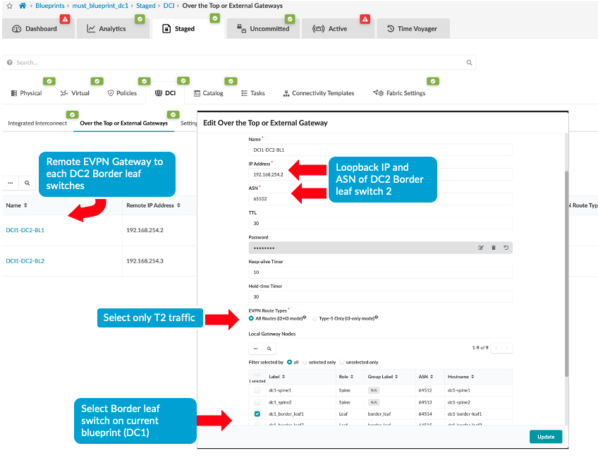 Figure 11: Create Over the Top or External Gateway between DC1 Border Leaf2 and DC2 Border Leaf2
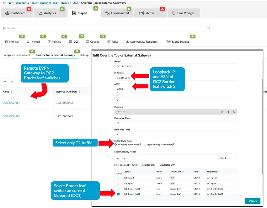
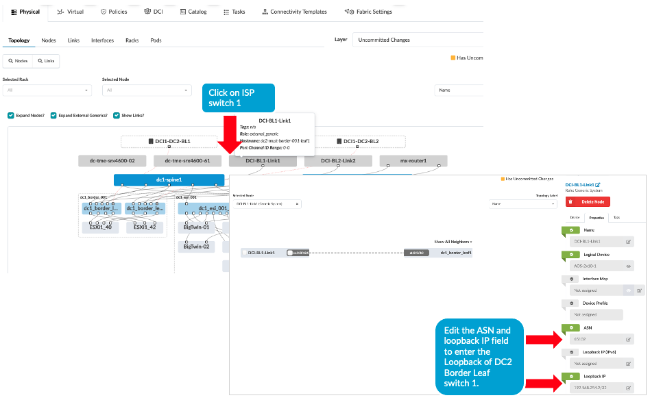
- Then ensure the ASN, Loopback IPs on the ISP switches reflects
that of remote data center’s border leaf switches, i.e.
DC2’s border leaf switch ASN and loopback IPs as shown below.
Navigate to Blueprint > Staged > Physical >
Topology then click on generic server representation of
ISP switches then on next screen right hand side navigate to
properties as shown below and update the ASN and loopback IP.
Repeat the same step for generic server ISP switch 2 as well.
Figure 12: ASN and Loopback Update of Remote Data Center for eBGP
- Navigate to DC1’s Blueprint > Uncommitted and commit all the changes. Note that the connectivity will not be up at this point as the ISP switches and the remote data center (DC2 in this instance) blueprint are not setup with DCI connectivity. This will be discussed in next step.
- Repeat all of the above steps for the remote data center, for
instance DC2. And then proceed to create the configuration on the
ISP Switches, see Configuring Interconnect
ISP switches.
Note: For the purposes of this lab, the configuration on the ISP switches were applied manually.
- MACSEC configuration was also applied to border leaf switches to encrypt traffic between the DC1 and DC2 data centers. Since Apstra doesn’t support MACSEC, it was applied using configlet, refer to section 1 for more information.
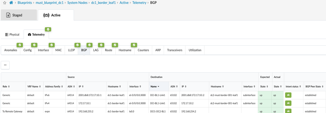
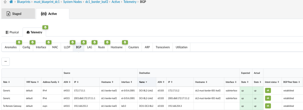
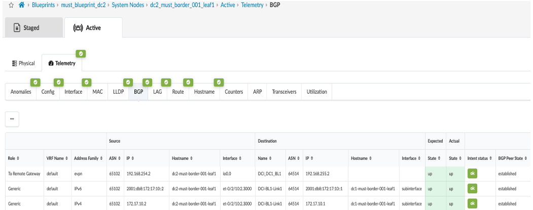
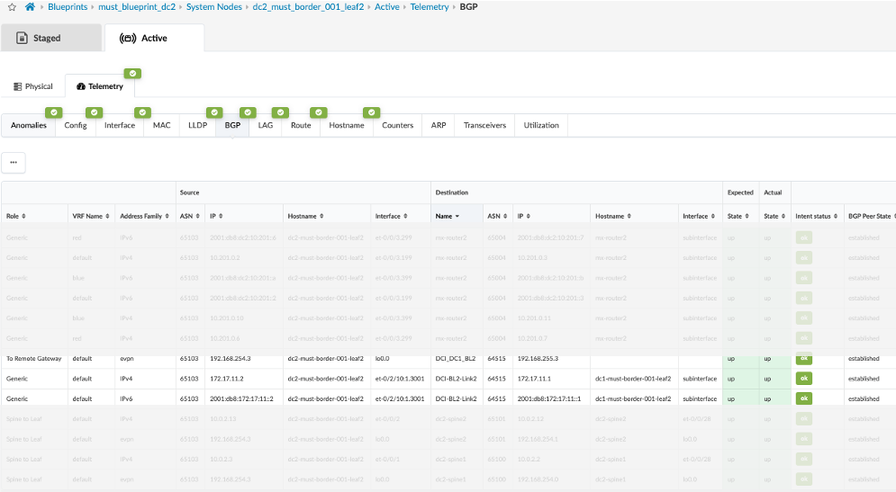
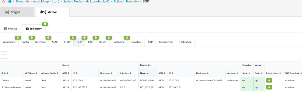
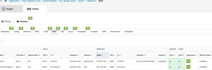
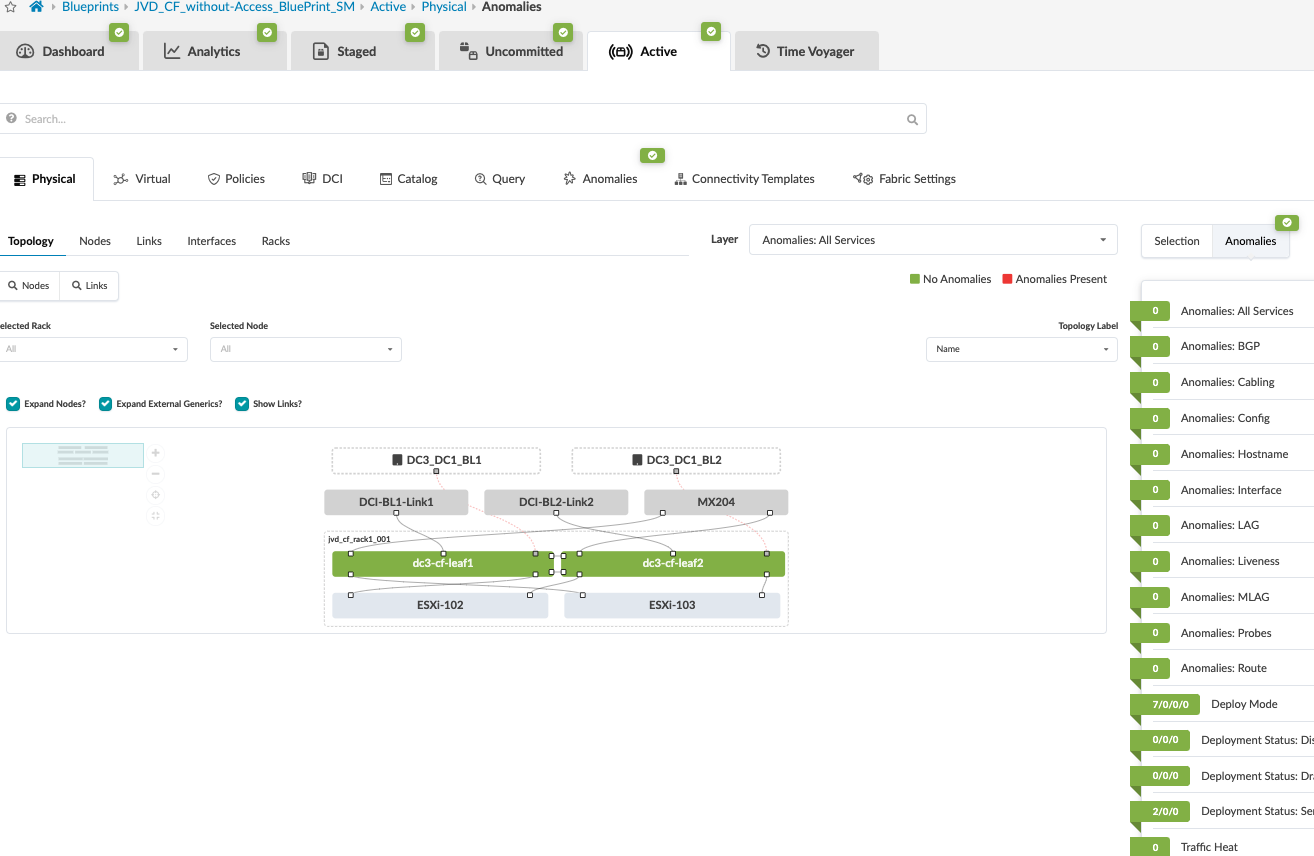
- Once configuration on ISP Switches and the remote data center (DC2) is committed, the connectivity should be up and Apstra should show no Anomalies related to the DCI connectivity. If Apstra shows anomalies for BGP, Interface etc, analyze and troubleshoot these.
Configuring Interconnect ISP Switches
For the DCI connectivity, the choice of connectivity between data centers depends on factors such as latency, convergence times during link or node failures, transport type (Layer 2/Layer 3) and hardware used to provide interconnectivity.
For the purposes of this lab, two QFX10002-36Q are used and the border leaves connect using 10G links. MPLS and L2-circuit are used to configure the Layer 2 cross connect. The configuration snippets show necessary configuration applied on one of the ISP switches to provide connectivity. Licenses for MPLS and L2-circuit were also applied. For more information on interface-switch cross connect refer the Layer2 cross-connect guide.
- The interfaces are created with circuit cross connect (CCC) encapsulation as
ethernet-ccc (configured the whole physical interface,
[set interfaces
            <interface_name> encapsulation ethernet-ccc]
. For the circuit to work logical interface (unit 0) should also be configured with familyccc [edit interfaces <interface_name> unit 0 family ccc]for interfaces connecting to the border leaves on both data centers. - Besides that, circuit cross connect switch
[edit protocols
            connections]
is configured using the interfaces set up as CCC in step 1. - Lastly for Layer 2 switching cross-connects to work, MPLS protocol should be enabled.
root@must-qfx10k-2> show configuration interfaces xe-0/0/18:0
description "OTT:DC1-BL1 to DC2-BL1";
mtu 9216;
encapsulation ethernet-ccc;
unit 0 {
    family ccc;
}

{master:0}
root@must-qfx10k-2> show configuration interfaces xe-0/0/18:2
description "OTT:DC1-BL1 to DC2-BL1";
mtu 9216;
encapsulation ethernet-ccc;
unit 0 {
    family ccc;
}

{master:0}
root@must-qfx10k-2> show configuration protocols
connections {
    interface-switch DC1-DC2 {
        interface xe-0/0/18:0.0;
        interface xe-0/0/18:2.0;
    }
}
mpls {
    interface all;
}
 lldp {
    interface all;
}
EVPN-VXLAN Type 2 Seamless Stitching (Layer 2 only with MACSEC) Design
For the Type 2 seamless stitching DCI design, only a subset of VLAN/VNI stretching between sites is configured. In this design MACSEC is also used for encrypting traffic between the two data centers. For this design, a 3-stage data center and a collapsed fabric data center are interconnected using layer 2 switches (QFX10002-36Q) as is described in Over-the-Top (OTT) (with MACSEC).
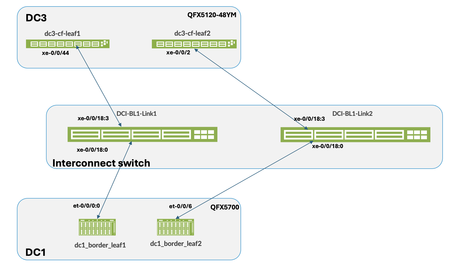
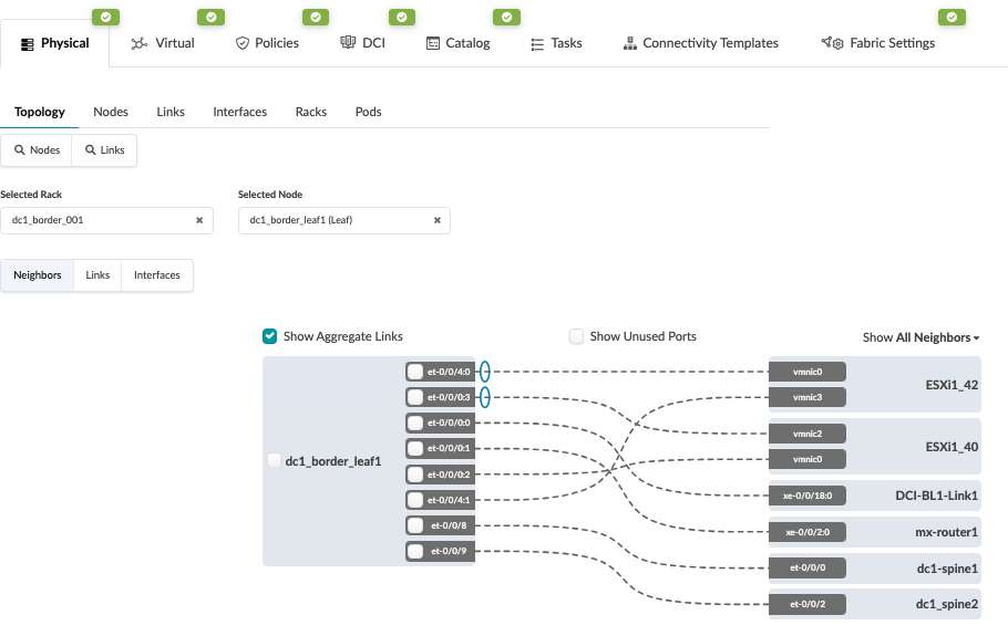
For the sake of clarity, the two data centers are referred to as DC1 and DC3 as is shown in Figure 17. Ensure both data centers are physically cabled to the Interconnect ISP switches.
The configuration steps in this case are similar to the OTT Design. For this both 3-stage (DC1) and Collapsed Fabric (DC3) blueprint should be up and running before proceeding. The steps for Type 2 DCI and for setting up MACSEC is as follows:
- Navigate to the blueprint of the first 3-stage Data Center (hereinafter referred to as
DC1). Configure the links to the Interconnect ISP switches as shown below for both border
leaves. Ensure the Link is also updated. For more information on creating an external
generic server refer the Apstra guide for adding links to existing Blueprint. Below is an
example of Border Leaf switch1 showing connectivity. Repeat same steps for Border Leaf
switch2. Figure 18: Border Leaf Switch 1 Connectivity
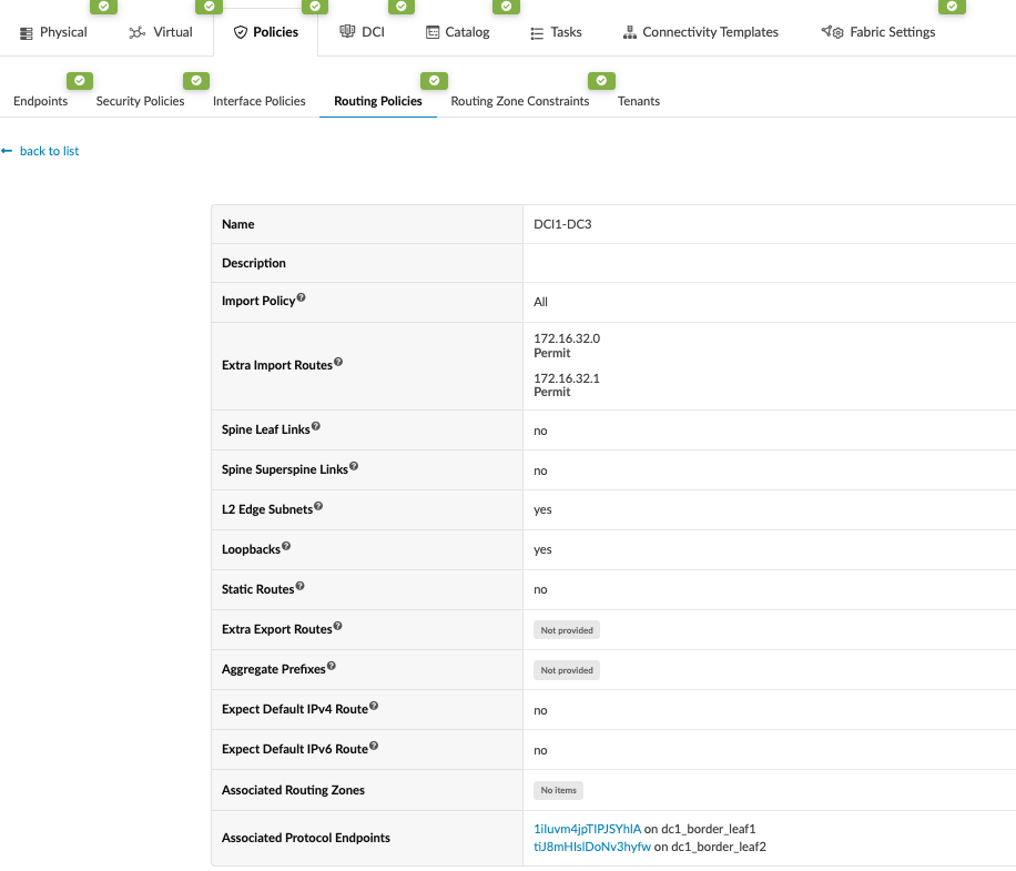
- Create Routing policy and allow the Loopback IP of the border leaf switches of remote
data center, in this case DC3. Navigate to Blueprint > Staged > Policies >
Routing Policies and create or modify relevant Policy and permit the import routes
of Loopback IPs of remote data center (DC3) border leaf switches. Figure 19: Routing Policy Allowing Routes Import from DC3
- Create Connectivity Templates to connect border leaf switches in the current blueprint
(DC1) to remote data center blueprint (DC3). This step creates the underlay connectivity
between the two data center which is VLAN tagged. The routing policy defined in previous
step is assigned for routes import. An underlay eBGP is also created between the border
leaf switch1 of both data centers. Similarly, configure the underlay connectivity, eBGP
between the border Leaf switch2 of both data centers. There should be two connectivity
templates created for each border leaf switch. Figure 20: Connectivity Template Created for Border Leaf1
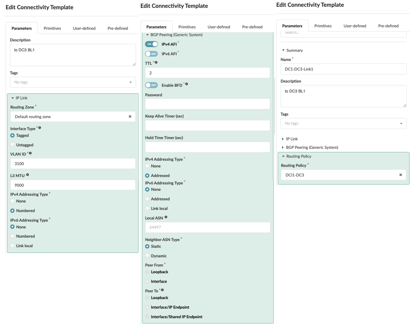 Figure 21: Connectivity Template Created for Border Leaf Switch2
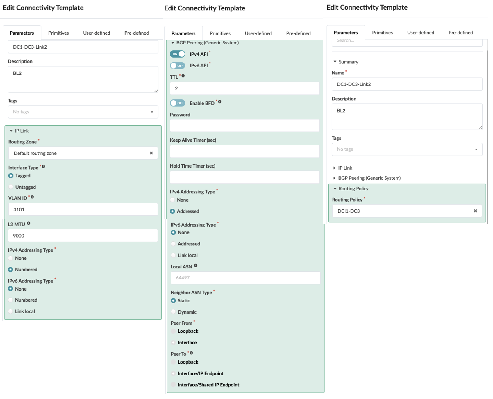
- Once the Connectivity templates are created, assign them to the border leaf switches as
shown below. For more information on Apstra connectivity templates, refer Juniper Apstra Guide. Figure 22: Border Leaf Switch1 Assigned to Connectivity Template
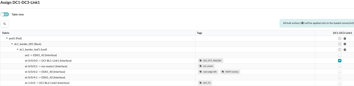 Figure 23: Border Leaf switch2 Assigned to Connectivity Template
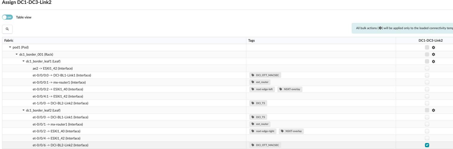
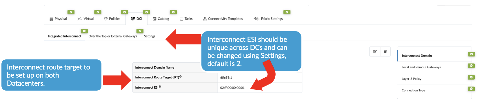
- To create the overlay connectivity, Navigate to Blueprint > Staged > DCI
and select the Integrated Interconnect to create the Interconnect domain. This
ensures the Interconnect ESI is different in both data centers (DC1 and DC3). Important Note: For seamless stitching, it is mandatory to select both remote border leaves to create logical full mesh overlay connectivity (as shown in Figure 26). In case of a link or node failure of the primary Border leaf switch, say in DC1, the Designated Forwarder role moves to the secondary border leaf switch. If the DC1 secondary Border leaf switch sends traffic to the remote Border leaf switch, which is not the Designated Forwarder, the routes will not be shared with the Primary Border leaf switch in the remote DC. Therefore, implementing a logical full mesh is both recommended and mandatory.Figure 24: Create Interconnect Domain
Then click on the “Local and Remote Gateway” to fill in the remote gateway i.e. DC3 border leaf switch information such as ASN, loopback etc as shown in Figure 25 and Figure 26.
Figure 25: Local and Remote Gateway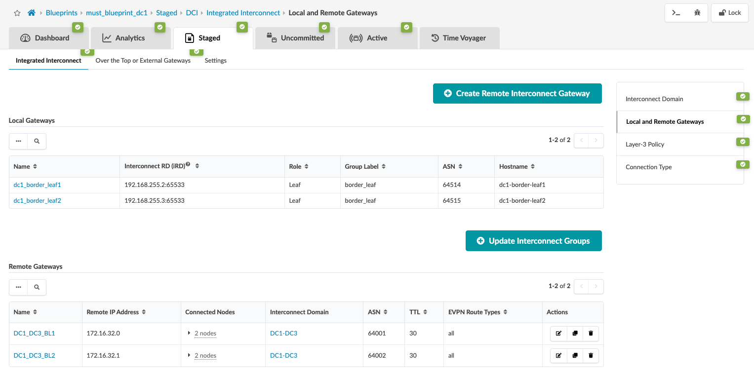 Figure 26: Create Remote and Local Gateway for both Border Leaf Switches
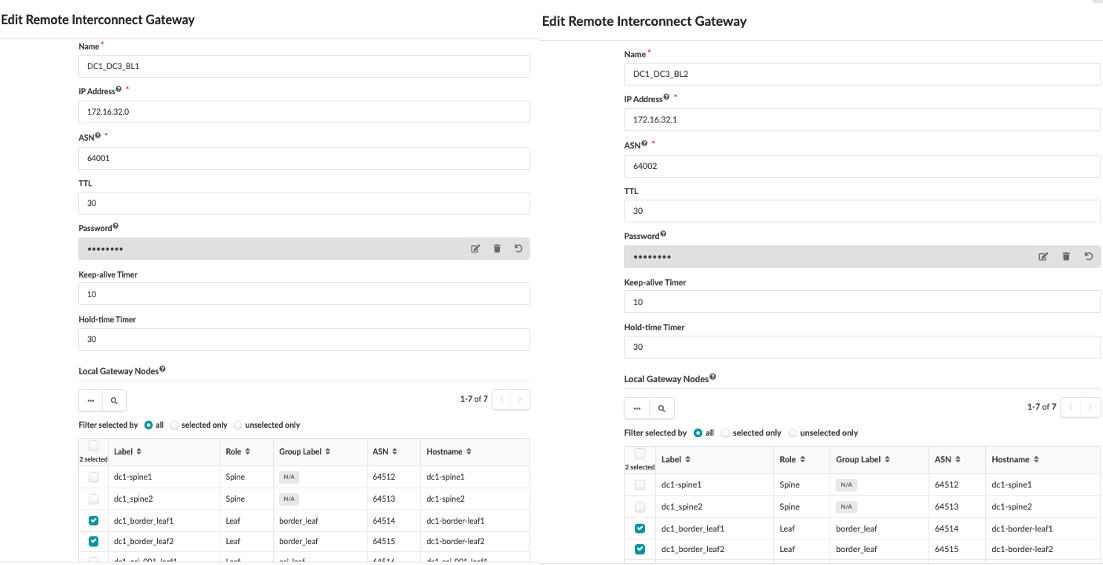
-
Before proceeding to associate the VXLAN/VNI to stretch across the DCI, navigate to Blueprint > Staged > Virtual Network and create Virtual Network. Refer Apstra guide for creating Virtual Network. The same Virtual Networks should be created in the remote data center blueprint for seamless stretching to work.
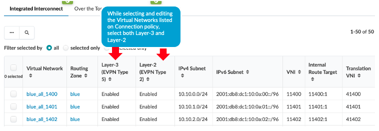
Then navigate back to Blueprint > Staged > DCI > Integrated Interconnect and select connection type and select the virtual networks listed and enable Layer 2 (EVPN Type 2). If necessary, translation VNI can also be configured. If translation VNI is configured, then the switch translates the VNI while it is forwarding traffic to a common VNI configured across the data center. The border leaf switch translates the VNI only if the translated VNI is included in the interconnected VNI list, which Apstra includes under[edit routing-instance evpn-1 protocols evpn interconnect interconnected-vni-list]as shown below in rendered configuration of border leaf switch1 .Figure 27: Border Leaf1 Switch Apstra Rendered Config Snippet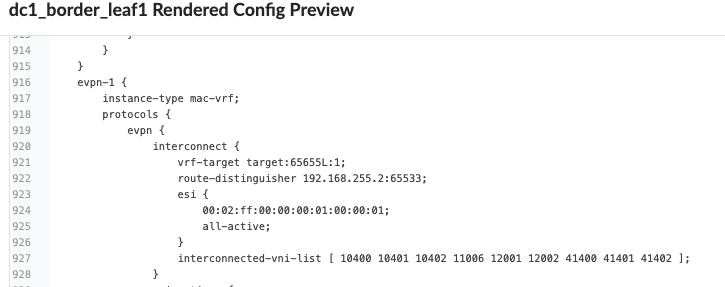 Figure 28: Selecting Virtual Network to Stretch and Apply Translation VNI
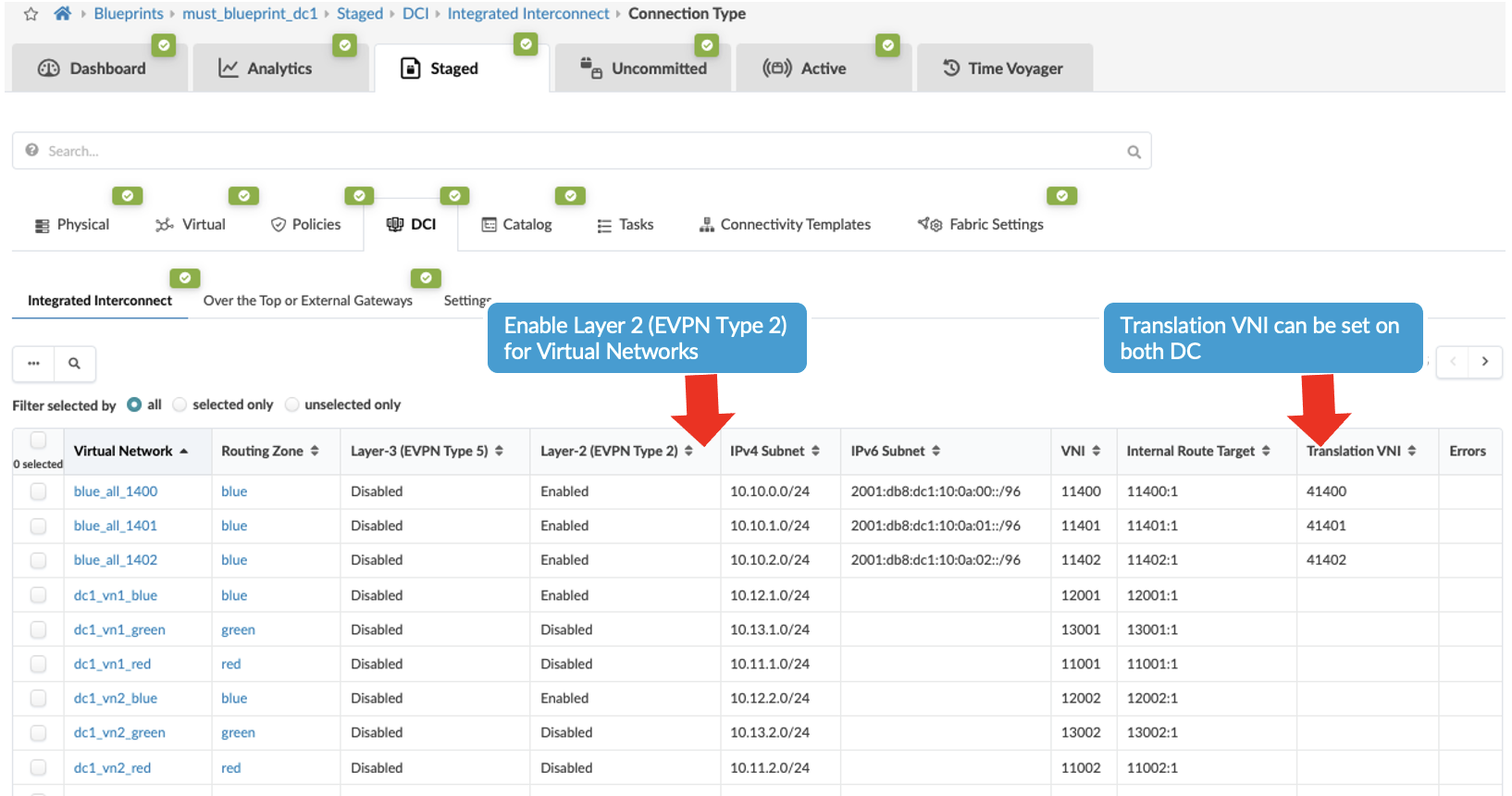
-
At this point the data center interconnectivity configuration should be ready. And if committed the connectivity between the two data centers should be established and the traffic between the data centers will be unencrypted. For this JVD design, MACSEC is set up between the two DCs which have been configured using configlet as Apstra does not natively support MACSEC, refer to section 1 for applying MACSEC using configlet.
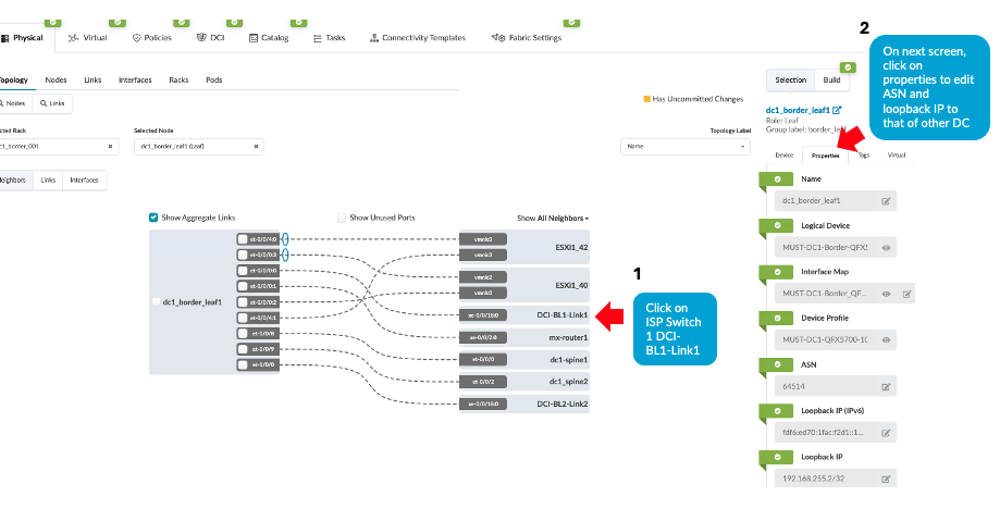
- Then ensure the ASN, loopback IPs on the ISP switches reflect that of remote data
center’s border leaf switches, i.e. DC3’s border leaf switch ASN and loopback IPs as shown
below. Navigate to Blueprint > Staged > Physical > Topology then click on
border leaf switch1 and as shown in then on next screen right hand side. Navigate to
properties as shown below and update the ASN and loopback IP. Repeat the same step for
generic server ISP switch 2 as well. Figure 29: Configuring ASN, Loopback of Remote Data Center Border leaf switch
- Navigate to DC1’s Blueprint > Uncommitted and commit all the changes. Note that the connectivity will not be up as at this point the ISP switches and the remote data center (DC3 in this instance) blueprint are not setup with DCI connectivity. This will be discussed in the next step.
- Repeat all of the above steps for the remote data center, for instance DC3. And then proceed to create configuration on the ISP Switches as discussed in section Configuring Interconnect ISP switches.
- Once configuration on ISP Switches and the remote data center (DC3) is committed, the connectivity should be up and Apstra should show no anomalies related to the DCI connectivity. If Apstra shows anomalies for BGP, cabling, Interface etc, analyze and troubleshoot these issues.
During validation of the VXLAN Type 2 stitching, it was noticed that Apstra omitted applying the DCI overlay EVPN BGP policy configuration on the collapsed fabric leaf switches to stop advertising overlay routes between collapsed leaf switches. However, the same was applied on 3-stage fabric spine switches to stop advertising overlay routes. Below configuration was applied using configlet on collapsed fabric leaf switches on existing EVPN eBGP configuration.
protocols {
   bgp {
       group l3clos-l-evpn {
           neighbor 192.168.253.1 export ( LEAF_TO_LEAF_EVPN_OUT && EVPN_EXPORT );
       }
   }
}

policy-options {
    policy-statement LEAF_TO_LEAF_EVPN_OUT {
        term LEAF_TO_LEAF_EVPN_OUT-10 {
            from {
                community FABRIC_EVI_TARGET;
                protocol bgp;
                protocol evpn;
            }
            then accept;
        }
        term LEAF_TO_LEAF_EVPN_OUT-20 {
            from {
                community EVPN_DCI_L2_TARGET;
                community EVPN_DCI_L3_TARGET_blue;
                community EVPN_DCI_L3_TARGET_red;
                protocol bgp;
                protocol evpn;
            }
            then reject;
        }
        term LEAF_TO_LEAF_EVPN_OUT-30 {
            then accept;
          }
        }
    }
EVPN-VXLAN Type 2 and Type 5 Seamless Stitching Design
This design and configuration is similar to EVPN-VXLAN Type 2 Seamless Stitching (Layer 2 only with MACSEC) design, with the exception that it involves Type 2 and Type 5 stitching design. However, while selecting the Virtual Networks for stretching, both Type 2 (Layer 2) and Type 5 (Layer 3) are enabled. When enabling Layer 3 for Virtual Networks to stretch across the data centers, the VRFs on the Layer-3 Policy tab in Apstra must also be enabled and a routing-policy must be associated with the VRF. Refer to the Apstra guide for more information.
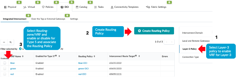
By enabling the Type 5 route for the VRF, Apstra applies below configuration to stitch the EVPN routes between data centers. The same Interconnect route target should be applied in the remote data center for seamless stitching to work.
evpn {
                interconnect {
                    vrf-target target:65655L:22222;
                    route-distinguisher 192.168.255.2:65530;
                }
Additional Configurations Applied
-
MACSEC
For this JVD design, MACSEC is setup between the two DCs which has been configured using configlet as Apstra does not natively support MACSEC, refer more information on setting MACSEC in the Day One Guide.
Note: For some platforms, such as QFX5700, logical interface (IFL) level MACSEC is unsupported. Therefore, QFX5700 (border gateways) are configured with physical interface (IFD).Property set for the OTT and Type2 Seamless stitching is imported into the Blueprint using Blueprint > Catalogue > Property set.
Figure 35: Property Set for MACSEC Configlet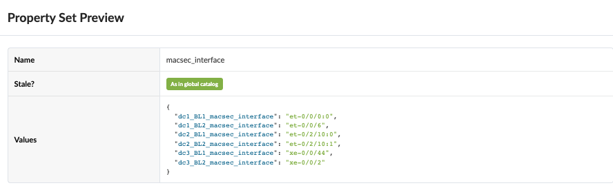
Configlet for MACSEC uses property set as shown in Figure 35 . The same configlet is used for both OTT and Type2 Seamless Stitching.
Figure 36: MACSEC Configlet in Apstra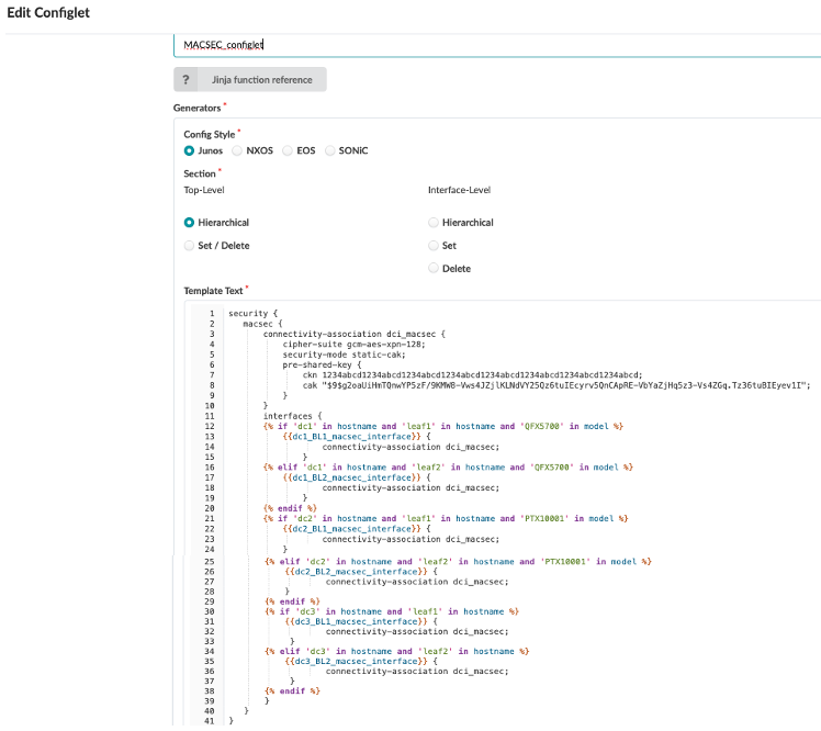
Below is the rendered configuration applied on both Border leaf switch1 and Border leaf switch2 in both data centers.
security { macsec { connectivity-association dci_macsec { cipher-suite gcm-aes-xpn-128; security-mode static-cak; pre-shared-key { ckn 1234abcd1234abcd1234abcd1234abcd1234abcd1234abcd1234abcd1234abcd; cak "$9$g2oaUiHmTQnwYP5zF/9KMW8-Vws4JZjlKLNdVY25Qz6tuIEcyrv5QnCApRE-VbYaZjHq5z3-Vs4ZGq.Tz36tuBIEyev1I"; } } interfaces { et-0/0/0:0 { connectivity-association dci_macsec; } } } } -
EVPN Type 5 routes host specific routes
For host specific routes in Apstra Fabric setting, enable EVPN Type 5 routes as shown below. This will increase routes depending on the number of hosts in the fabric. The default setting for EVPN Type 5 routes is disabled. For the DCI Type 2 and Type 5 seamless stitching, navigate to Blueprint > Staged > Fabric Settings. If this setting is disabled, then the routes shared will be the subnet prefix that is configured on the Virtual Network IP Subnet.
Figure 37: Fabric Setting to Enable Host Specific IP Routes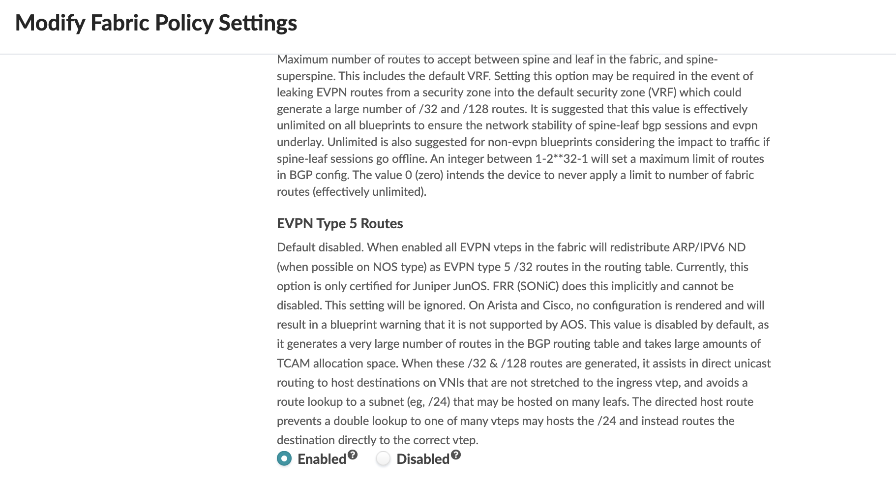
- BFD for better convergence times during node failures
To improve convergence time during link and node failures BFD was applied to the DCI overlay BGP session. Apstra does not apply BFD for DCI overlay BGP session. Hence the configlet was used to set up BFD to the DCI overlay BGP session. For the BFD overlay session, the connectivity template was used to apply BFD.
set protocols bgp group evpn-gw bfd-liveness-detection minimum-interval 3000 multiplier 3