Appendix: Test Case Example Information
Virtual Test Lab
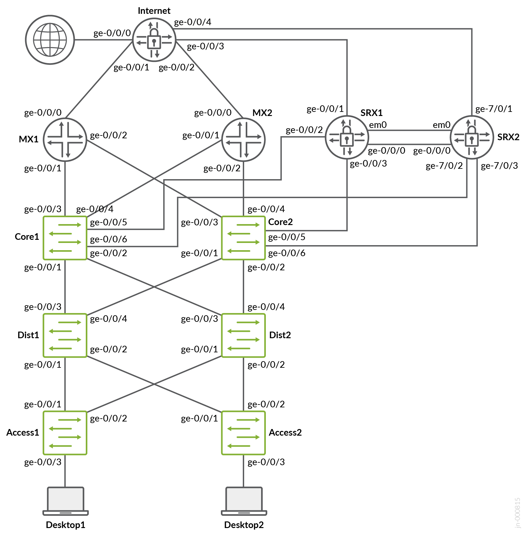
The examples in this appendix to the JVDE are evaluated in a virtual test lab consisting of a vJunos-switch , a vMX router, and vSRX V3.0 firewalls. We did not create a pair of virtual service block switches but ensured that both types of WAN routers (router or firewall) were available as redundant pairs. This is not the same lab used for testing that required the use physical hardware. We use this as an example and something you can potentially build yourself with environments such as EVE-NG to build your own labs to test the configuration examples. The fabric, in this case, was configured as IP Clos.
L2 Exit with Stretched VLAN
Previous versions of this JVD-E included an example configuration for L2 Exit using stretched VLANs. However, this led to significant issues, as users often overlooked the fact that it was never intended for production use. To avoid further confusion, we have decided to remove the example entirely. While it may still appear in older documentation, it remains an unsupported and non-production-grade solution.
L2 Exit with Transport VLAN
When doing any VLAN or VRF creation with campus fabric remember the following best practices:Create all VLANs in a switch template and then import them in the Campus Fabric dialogue. Creating the VLANs anywhere else in the Mist GUI ultimately leads to inconsistency which makes it hard to resolve issues.With the exception of the service block functions, do not create VRFs outside of the Campus Fabric dialogue.The transport VLAN method requires you to create VRFs manually on the service block function and add the transport VLAN and routes locally to the VRFs. Do not create the VRFs or routes in the Campus Fabric dialogue.We recommend that you create port profiles within switch templates so that any changes are in sync on all switches in the fabric.
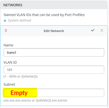
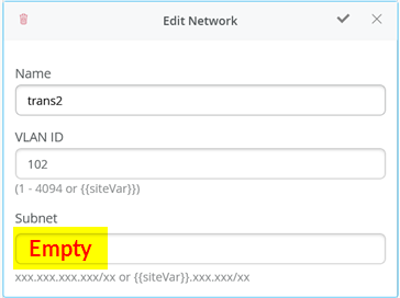
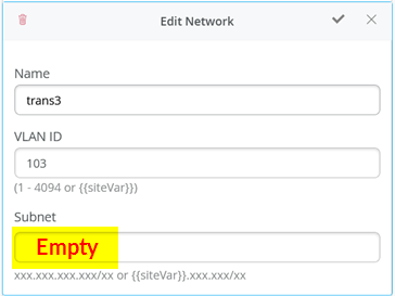
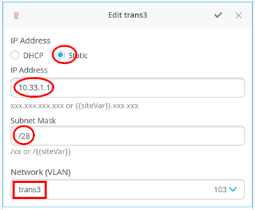
When defining the transport VLANs in the switch template, do not set the subnet information. You configure this information later as Additional IP Subnet on each service block function. See Figure 1 , Figure 2 , and Figure 3 .
The following CLI configuration shows the exported version of the switch template used in the transport VLAN fabric. This allows you to review our setup when importing. As you can see, there is a minimum of two VLANs per VRF plus an additional transport VLAN per VRF.
{
“additional_config_cmds”: [],
“networks”: {
“vlan1099”: {
“vlan_id”: 1099,
“subnet”: “10.99.99.0/24”
},
“vlan1088”: {
“vlan_id”: 1088,
“subnet”: “10.88.88.0/24”
},
“vlan1033”: {
“vlan_id”: 1033,
“subnet”: “10.33.33.0/24”
},
“vlan1091”: {
“vlan_id”: 1091,
“subnet”: “10.99.91.0/24”
},
“vlan1081”: {
“vlan_id”: 1081,
“subnet”: “10.88.81.0/24”
},
“vlan1031”: {
“vlan_id”: 1031,
“subnet”: “10.33.31.0/24”
},
“trans1”: {
“vlan_id”: “101”,
“subnet”: “”
},
“trans2”: {
“vlan_id”: “102”,
“subnet”: “”
},
“trans3”: {
“vlan_id”: “103”,
“subnet”: “”
}
},
“port_usages”: {
“vlan1099”: {
“mode”: “access”,
“disabled”: false,
“port_network”: “vlan1099”,
“voip_network”: null,
“stp_edge”: false,
“mac_auth_protocol”: null,
“all_networks”: false,
“networks”: null,
“port_auth”: null,
“enable_mac_auth”: null,
“mac_auth_only”: null,
“guest_network”: null,
“bypass_auth_when_server_down”: null,
“speed”: “auto”,
“duplex”: “auto”,
“mac_limit”: 0,
“persist_mac”: false,
“poe_disabled”: false,
“enable_qos”: false,
“storm_control”: {},
“mtu”: null,
“description”: “”,
“disable_autoneg”: false
},
“vlan1088”: {
“mode”: “access”,
“disabled”: false,
“port_network”: “vlan1088”,
“voip_network”: null,
“stp_edge”: false,
“mac_auth_protocol”: null,
“all_networks”: false,
“networks”: null,
“port_auth”: null,
“enable_mac_auth”: null,
“mac_auth_only”: null,
“guest_network”: null,
“bypass_auth_when_server_down”: null,
“speed”: “auto”,
“duplex”: “auto”,
“mac_limit”: 0,
“persist_mac”: false,
“poe_disabled”: false,
“enable_qos”: false,
“storm_control”: {},
“mtu”: null,
“description”: “”,
“disable_autoneg”: false
},
“dynamic”: {
“mode”: “dynamic”,
“rules”: []
}
},
“switch_matching”: {
“enable”: true,
“rules”: []
},
“switch_mgmt”: {
“config_revert_timer”: 10,
“root_password”: “<password>”,
“protect_re”: {
“enabled”: false
},
“tacacs”: {
“enabled”: false
}
},
“mist_nac”: {
“enabled”: true,
“network”: null
},
“radius_config”: {
“auth_servers”: [],
“acct_servers”: [],
“auth_servers_timeout”: 5,
“auth_servers_retries”: 3,
“fast_dot1x_timers”: false,
“acct_interim_interval”: 0,
“auth_server_selection”: “ordered”,
“coa_enabled”: false,
“coa_port”: “”
},
“vrf_config”: {
“enabled”: false
},
“remote_syslog”: {
“enabled”: false
},
“snmp_config”: {
“enabled”: false
},
“dhcp_snooping”: {
“enabled”: false
},
“dns_servers”: [],
“dns_suffix”: [],
“ntp_servers”: [],
“acl_policies”: [],
“port_mirroring”: {},
“name”: “campus-fabric”
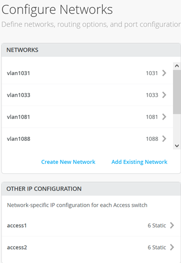
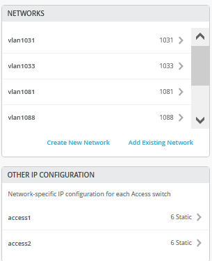
}Within the Campus Fabric Configuration dialogue, there is a section called Configure Networks. This is where you import your six access VLANs from the switch template. When finished, the configuration should be as shown in Figure 4 and the result in our case will look as shown below. Since the three transport VLANs are not part of the access layer, they are not defined in the service block function.
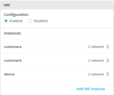
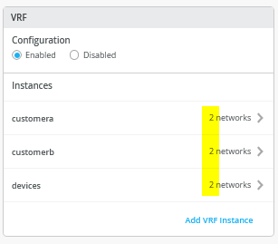
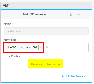
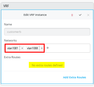
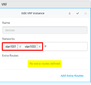
Next, you create 3 VRFs and attach two of the access networks to each VRF as shown in Figure 5 .
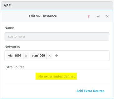
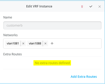
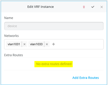
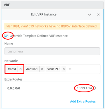
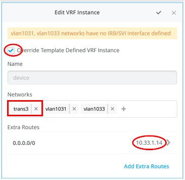
Next, go to each VRF and confirm that you only have access networks defined with no default route. You will define the transport VLANs and default routes later in the service block function. See Figure 6, Figure 7 , and Figure 8 .
Core1 and Core2 Switch Configuration
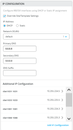
In the transport VLAN attach example, the service block function is virtual and co-located on the core switch. Therefore, you must configure the two core switches. The following pseudocode represents the configuration you must apply to the core1 and core2 switches:
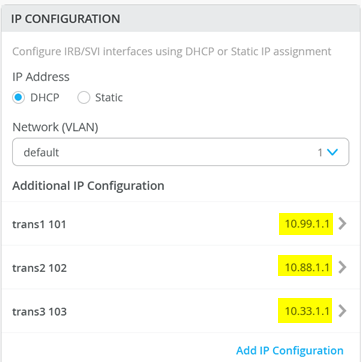
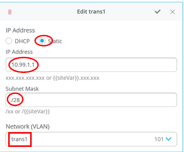
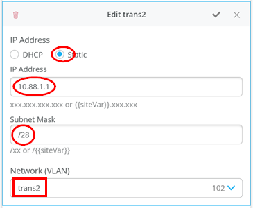
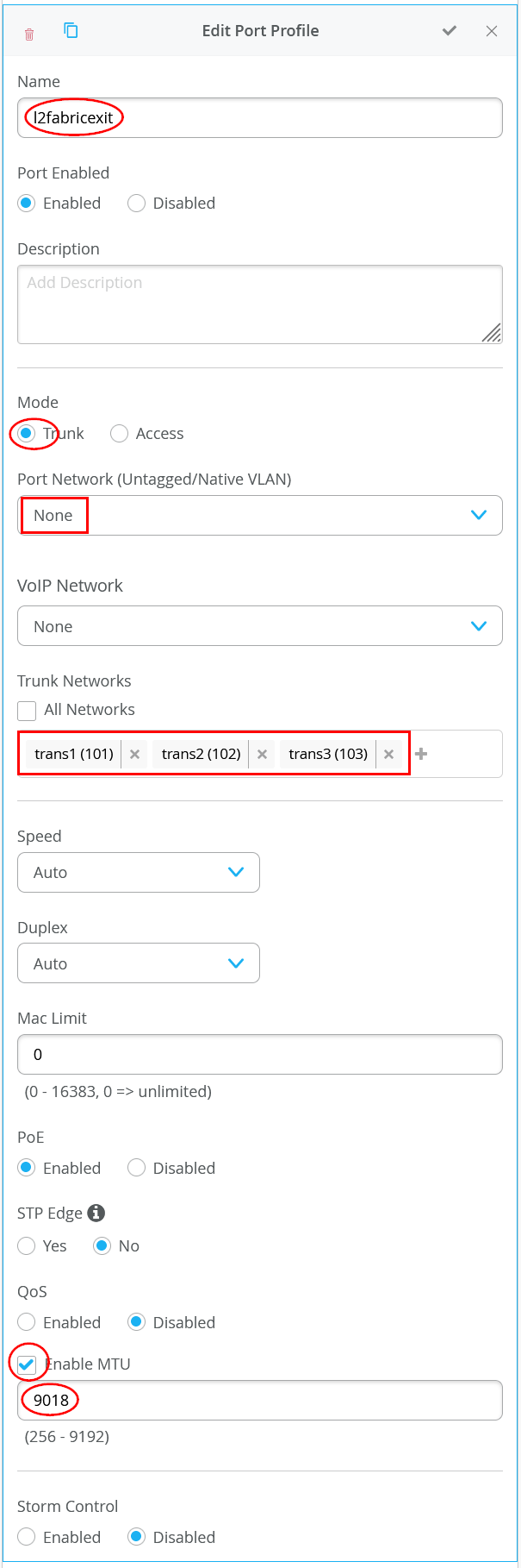
# configure the additional IP subnet 10.99.1.1/28 to network/VLAN:trans1
# configure the additional IP subnet 10.88.1.1/28 to network/VLAN:trans2
# configure the additional IP subnet 10.33.1.1/28 to network/VLAN:trans3
#
# Create a new local Port Profile called 'l2fabricexit' and configure:
# Mode='Trunk'
# Port Network (Untagged/Native VLAN)='None'
# Add the following 3 Networks as Trunk Networks:
# Network=trans1
# Network=trans2
# Network=trans3
# MTU='9018'
#
# Create a new Port configuration where:
# Port IDs=ge-0/0/3
# Interface=L2 Interface
# Configuration Profile=l2fabricexit
# Port Aggregation=Enable/Checked
# AE Index=11
# ESI-LAG=Enable/Checked
#
# Create a new Port configuration where:
# Port IDs=ge-0/0/4
# Interface=L2 Interface
# Configuration Profile=l2fabricexit
# Port Aggregation=Enable/Checked
# AE Index=12
# ESI-LAG=Enable/Checked
#
# In VRF Configuration
# Override Site/Template Settings=Checked
# In Instance customera
# Override Template Defined VRF Instance=Checked
# Add the Network trans1 to the existing list of networks
# Add the Extra Route 0.0.0.0/0 with via: 10.99.1.14
#
# In Instance customerb
# Override Template Defined VRF Instance=Checked
# Add the Network trans2 to the existing list of networks
# Add the Extra Route 0.0.0.0/0 with via: 10.88.1.14
#
# In Instance device
# Override Template Defined VRF Instance=Checked
# Add the Network trans3 to the existing list of networks
# Add the Extra Route 0.0.0.0/0 with via: 10.33.1.14
The following four images display the Mist GUI configuration that results from the previous pseudocode starting with the additional IP configuration required to assign the local IP addresses to each transport VLAN.
Next, you define the Port Profile used for the uplinks. It is critical that you only include the transport VLAN in the Trunk Networks definition since only those VLANs are used and visible to the WAN router.
Next, you assign the port profiles to each uplink port.
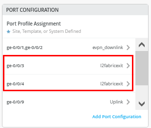
Figure 15 shows the configuration of the first uplink to the first WAN router.
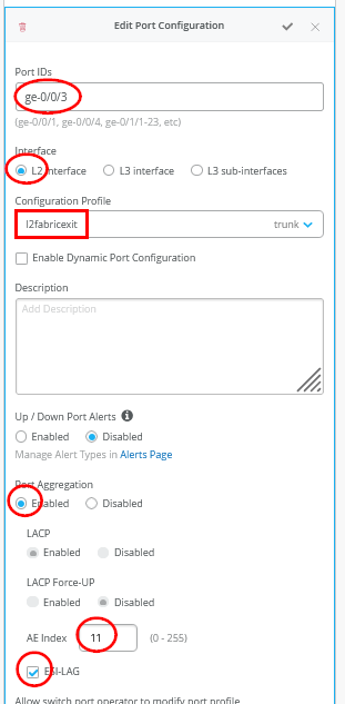
Figure 16 shows the configuration of the second uplink to the first WAN router.
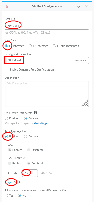
You must ensure that the AE Indexes on each service block function are in sync with each other towards the same WAN router and that you define them each as ESI-LAG. You must also ensure that you don’t reuse an AE Index that is already defined elsewhere in the fabric service block.
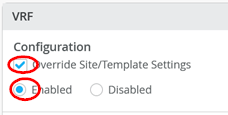
Next you create and modify local VRFs. Remember this is an exception made only for the transport VLAN exit method. Usually, the fabric creates the VRFs automatically. In this case we must enable the Override Site/Template Settings checkbox in the VRF configuration. Figure 17 shows the required configuration in the Mist GUI.
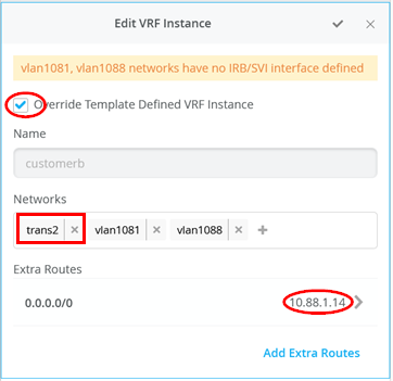
Next you must perform the following three configurations in each of your three VRS instances:
- Enable Override Template Defined VRF Instance checkbox
- Add your transport VLAN to the pre-populated list of access VLANs
- Add a default route where the gateway IP address is the VRRP-VIP address of your WAN router.
- Figure 18 , Figure 19 , and Figure 20 show the override configurations for each of the three VRFs.
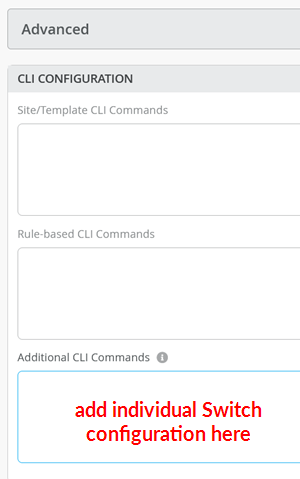
Now you must configure additional CLI to modify the transport VLANs to use VGA configuration to help avoid excess hair-pin routing of traffic within the fabric. In the switch configuration for each of your service block function switches, locate the CLI Configuration section in the Mist GUI. You must paste the required configuration into the field indicated in Figure 21.
The example CLI configuration for your core1 switch, is shown in the following code block. We have configured the static IP address as the virtual gateway IP address + 1 (10.99.1.2).
# when service block function is a EX92xx change to VGA with the below
delete groups top routing-instances evpn_vs protocols evpn default-gateway do-not-advertise
set groups top routing-instances evpn_vs protocols evpn default-gateway no-gateway-community
#
# on non-EX92xx switches change to VGA with the below
# delete groups top protocols evpn default-gateway do-not-advertise
# set groups top protocols evpn default-gateway no-gateway-community
#
# modify our transport VLANs to VGA
delete interfaces irb unit 101 family inet address 10.99.1.1/28
set interfaces irb unit 101 family inet address 10.99.1.2/28 virtual-gateway-address 10.99.1.1
set interfaces irb unit 101 virtual-gateway-accept-data
set interfaces irb unit 101 virtual-gateway-v4-mac 00:00:5e:e4:05:01
#
delete interfaces irb unit 102 family inet address 10.88.1.1/28
set interfaces irb unit 102 family inet address 10.88.1.2/28 virtual-gateway-address 10.88.1.1
set interfaces irb unit 102 virtual-gateway-accept-data
set interfaces irb unit 102 virtual-gateway-v4-mac 00:00:5e:e4:05:02
#
delete interfaces irb unit 103 family inet address 10.33.1.1/28
set interfaces irb unit 103 family inet address 10.33.1.2/28 virtual-gateway-address 10.33.1.1
set interfaces irb unit 103 virtual-gateway-accept-data
set interfaces irb unit 103 virtual-gateway-v4-mac 00:00:5e:e4:05:03
For your core2 switch, only the static IP addresses of the transport VLAN are changed to be the virtual gateway IP address + 2 (10.88.1.3).
# when service block function is a EX92xx change to VGA with the below
delete groups top routing-instances evpn_vs protocols evpn default-gateway do-not-advertise
set groups top routing-instances evpn_vs protocols evpn default-gateway no-gateway-community
#
# on all non-EX92xx switches change to VGA with the below
# delete groups top protocols evpn default-gateway do-not-advertise
# set groups top protocols evpn default-gateway no-gateway-community
#
# modify our transport VLANs to VGA
delete interfaces irb unit 101 family inet address 10.99.1.1/28
set interfaces irb unit 101 family inet address 10.99.1.3/28 virtual-gateway-address 10.99.1.1
set interfaces irb unit 101 virtual-gateway-accept-data
set interfaces irb unit 101 virtual-gateway-v4-mac 00:00:5e:e4:05:01
#
delete interfaces irb unit 102 family inet address 10.88.1.1/28
set interfaces irb unit 102 family inet address 10.88.1.3/28 virtual-gateway-address 10.88.1.1
set interfaces irb unit 102 virtual-gateway-accept-data
set interfaces irb unit 102 virtual-gateway-v4-mac 00:00:5e:e4:05:02
#
#
delete interfaces irb unit 103 family inet address 10.33.1.1/28
set interfaces irb unit 103 family inet address 10.33.1.3/28 virtual-gateway-address 10.33.1.1
set interfaces irb unit 103 virtual-gateway-accept-data
set interfaces irb unit 103 virtual-gateway-v4-mac 00:00:5e:e4:05:03
Keep in mind that our test lab used virtual EX9214 switches as core switches. In most production environments you will not use an EX92xx switch. Therefore, you must uncomment the two lines that are commented out in the previous configuration snippet:
# delete groups top protocols evpn default-gateway do-not-advertise
# set groups top protocols evpn default-gateway no-gateway-community
Service block for each transport VLAN used per VRF you must manually set the MAC address of the virtual gateway address used on the IRB interface. In our example, we used different MAC addresses per transport VLAN because it’s easier to debug.
Juniper MX as WAN Router
The following CLI snippet example contains the configuration of the interfaces, the VRRP gateway redundancy, and the static routes for the first WAN router. You may need to add default routes and interfaces to complete the configuration.
set system host-name wanrouter1
#
set chassis aggregated-devices ethernet device-count 10
#
delete interfaces ae0
delete policy-options policy-statement fabric
delete policy-options policy-statement internet
delete routing-instances public-int
#
set protocols lldp port-id-subtype interface-name
set protocols lldp interface all
set protocols lldp-med interface all
#
delete interfaces ge-0/0/1
set interfaces ge-0/0/1 gigether-options 802.3ad ae11
delete interfaces ge-0/0/2
set interfaces ge-0/0/2 gigether-options 802.3ad ae11
delete interfaces ae11
set interfaces ae11 mtu 9018
set interfaces ae11 aggregated-ether-options lacp active
set interfaces ae11 aggregated-ether-options lacp admin-key 11
set interfaces ae11 unit 0 family bridge interface-mode trunk
set interfaces ae11 unit 0 family bridge vlan-id-list 101
set interfaces ae11 unit 0 family bridge vlan-id-list 102
set interfaces ae11 unit 0 family bridge vlan-id-list 103
#
set bridge-domains trans1 vlan-id 101
set bridge-domains trans1 routing-interface irb.101
set bridge-domains trans2 vlan-id 102
set bridge-domains trans2 routing-interface irb.102
set bridge-domains trans3 vlan-id 103
set bridge-domains trans3 routing-interface irb.103
#
set interfaces irb unit 101 family inet address 10.99.1.13/28 vrrp-group 1 virtual-address 10.99.1.14
set interfaces irb unit 101 family inet address 10.99.1.13/28 vrrp-group 1 priority 110
set interfaces irb unit 101 family inet address 10.99.1.13/28 vrrp-group 1 accept-data
#
set interfaces irb unit 102 family inet address 10.88.1.13/28 vrrp-group 2 virtual-address 10.88.1.14
set interfaces irb unit 102 family inet address 10.88.1.13/28 vrrp-group 2 priority 110
set interfaces irb unit 102 family inet address 10.88.1.13/28 vrrp-group 2 accept-data
#
set interfaces irb unit 103 family inet address 10.33.1.13/28 vrrp-group 3 virtual-address 10.33.1.14
set interfaces irb unit 103 family inet address 10.33.1.13/28 vrrp-group 3 priority 110
set interfaces irb unit 103 family inet address 10.33.1.13/28 vrrp-group 3 accept-data
#
set routing-options static route 10.99.91.0/24 next-hop 10.99.1.1
set routing-options static route 10.99.99.0/24 next-hop 10.99.1.1
set routing-options static route 172.16.193.0/24 next-hop 10.99.1.1
#
set routing-options static route 10.88.81.0/24 next-hop 10.88.1.1
set routing-options static route 10.88.88.0/24 next-hop 10.88.1.1
set routing-options static route 172.16.194.0/24 next-hop 10.88.1.1
#
set routing-options static route 10.33.31.0/24 next-hop 10.33.1.1
set routing-options static route 10.33.33.0/24 next-hop 10.33.1.1
set routing-options static route 172.16.195.0/24 next-hop 10.33.1.1
On the second WAN router, the notable configuration changes are the AE keys and indexes, and the static IP addresses.
set system host-name wanrouter2
#
set chassis aggregated-devices ethernet device-count 10
#
set protocols lldp port-id-subtype interface-name
set protocols lldp interface all
set protocols lldp-med interface all
#
delete interfaces ge-0/0/1
set interfaces ge-0/0/1 gigether-options 802.3ad ae12
delete interfaces ge-0/0/2
set interfaces ge-0/0/2 gigether-options 802.3ad ae12
#
delete interfaces ae12
set interfaces ae12 mtu 9018
set interfaces ae12 aggregated-ether-options lacp active
set interfaces ae12 aggregated-ether-options lacp admin-key 12
set interfaces ae12 unit 0 family bridge interface-mode trunk
set interfaces ae12 unit 0 family bridge vlan-id-list 101
set interfaces ae12 unit 0 family bridge vlan-id-list 102
set interfaces ae12 unit 0 family bridge vlan-id-list 103
#
set bridge-domains trans1 vlan-id 101
set bridge-domains trans1 routing-interface irb.101
set bridge-domains trans2 vlan-id 102
set bridge-domains trans2 routing-interface irb.102
set bridge-domains trans3 vlan-id 103
set bridge-domains trans3 routing-interface irb.103
#
set interfaces irb unit 101 family inet address 10.99.1.12/28 vrrp-group 1 virtual-address 10.99.1.14
set interfaces irb unit 101 family inet address 10.99.1.12/28 vrrp-group 1 accept-data
#
set interfaces irb unit 102 family inet address 10.88.1.12/28 vrrp-group 2 virtual-address 10.88.1.14
set interfaces irb unit 102 family inet address 10.88.1.12/28 vrrp-group 2 accept-data
#
set interfaces irb unit 103 family inet address 10.33.1.12/28 vrrp-group 3 virtual-address 10.33.1.14
set interfaces irb unit 103 family inet address 10.33.1.12/28 vrrp-group 3 accept-data
#
set routing-options static route 10.99.91.0/24 next-hop 10.99.1.1
set routing-options static route 10.99.99.0/24 next-hop 10.99.1.1
set routing-options static route 172.16.193.0/24 next-hop 10.99.1.1
#
set routing-options static route 10.88.81.0/24 next-hop 10.88.1.1
set routing-options static route 10.88.88.0/24 next-hop 10.88.1.1
set routing-options static route 172.16.194.0/24 next-hop 10.88.1.1
#
set routing-options static route 10.33.31.0/24 next-hop 10.33.1.1
set routing-options static route 10.33.33.0/24 next-hop 10.33.1.1
set routing-options static route 172.16.195.0/24 next-hop 10.33.1.1
You may wonder about those static routes in the 172.16.19x.0 range. Remember that IP Clos is an anycast fabric. As such, you must have th static routes to prepare for when the DHCP relay will use IP addresses in the fabric overlay. See Figure 22 for an example definition
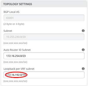
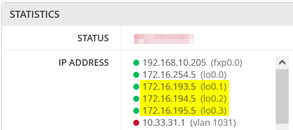
The overlay Loopbacks IPs are assigned to each VRF on a switch as a /24 range. You can figure them out by looking at a fabric access switch as shown in Figure 23 . Hence, you must map them back like any other additional VLAN attached to the VRF to achieve the required reachability.
The following commands help to debug the connections on WAN router1.
root@wanrouter1> show lldp neighbors
Local Interface    Parent Interface    Chassis Id                               Port info          System Name
ge-0/0/0           -                   4c:96:14:95:09:80                        516                 internet
ge-0/0/1           ae11                2c:6b:f5:3a:42:c0                        ge-0/0/3            core1
ge-0/0/2           ae11                2c:6b:f5:7f:7d:c0                        ge-0/0/3            core2
.
root@wanrouter1> show lacp interfaces
Aggregated interface: ae11
    LACP state:           Role   Exp   Def  Dist  Col  Syn  Aggr  Timeout  Activity
      ge-0/0/1           Actor    No    No   Yes  Yes  Yes   Yes     Fast    Active
      ge-0/0/1         Partner    No    No   Yes  Yes  Yes   Yes     Fast    Active
      ge-0/0/2           Actor    No    No   Yes  Yes  Yes   Yes     Fast    Active
      ge-0/0/2         Partner    No    No   Yes  Yes  Yes   Yes     Fast    Active
    LACP protocol:        Receive State  Transmit State          Mux State
      ge-0/0/1                  Current   Fast periodic Collecting distributing
      ge-0/0/2                  Current   Fast periodic Collecting distributing
.
root@wanrouter1> show vrrp
Interface     State       Group   VR state VR Mode   Timer    Type   Address
irb.101       up              1   master   Active      A  0.350 lcl    10.99.1.13
                                                                vip    10.99.1.14
irb.102       up              2   master   Active      A  0.625 lcl    10.88.1.13
                                                                vip    10.88.1.14
irb.103       up              3   master   Active      A  0.830 lcl    10.33.1.13
                                                                vip    10.33.1.14
The following commands help you to debug connections on WAN router2.
root@wanrouter2> show lldp neighbors
Local Interface    Parent Interface    Chassis Id                               Port info          System Name
ge-0/0/0           -                   4c:96:14:95:09:80                        517                 internet
ge-0/0/1           ae12                2c:6b:f5:3a:42:c0                        ge-0/0/4            core1
ge-0/0/2           ae12                2c:6b:f5:7f:7d:c0                        ge-0/0/4            core2
.
root@wanrouter2> show lacp interfaces
Aggregated interface: ae12
    LACP state:           Role   Exp   Def  Dist  Col  Syn  Aggr  Timeout  Activity
      ge-0/0/1           Actor    No    No   Yes  Yes  Yes   Yes     Fast    Active
      ge-0/0/1         Partner    No    No   Yes  Yes  Yes   Yes     Fast    Active
      ge-0/0/2           Actor    No    No   Yes  Yes  Yes   Yes     Fast    Active
      ge-0/0/2         Partner    No    No   Yes  Yes  Yes   Yes     Fast    Active
    LACP protocol:        Receive State  Transmit State          Mux State
      ge-0/0/1                  Current   Fast periodic Collecting distributing
      ge-0/0/2                  Current   Fast periodic Collecting distributing
.
root@wanrouter2> show vrrp
Interface     State       Group   VR state VR Mode   Timer    Type   Address
irb.101       up              1   backup   Active      D  2.811 lcl    10.99.1.12
                                                                vip    10.99.1.14
                                                                mas    10.99.1.13
irb.102       up              2   backup   Active      D  3.303 lcl    10.88.1.12
                                                                vip    10.88.1.14
                                                                mas    10.88.1.13
irb.103       up              3   backup   Active      D  2.798 lcl    10.33.1.12
                                                                vip    10.33.1.14
                                                                mas    10.33.1.13
L3 Exit With eBGP Routing Protocol
When you create any VLAN or VRF creation with campus fabric remember the following best practices:
- Create all VLANs in a switch template and then import them into the Campus Fabric Dialogue. Creating the VLANs anywhere else in the Mist GUI ultimately leads to inconsistency which makes it hard to resolve issues.
- If needed, the fabric creates any required VRFs. Do not create VRFs manually elsewhere in the Mist GUI.
- We recommend that you create port profiles within switch templates so that any changes are in sync on all switches in a fabric.
Before you begin, you need a plan for:
- How to implement the routing protocol and route exchange
- How to configure the P2P links
- How to distribute the VLAN assignment that is indirectly used to identify the VRF
Even if the VRF already exists elsewhere in the fabric, such as on the access switch for IP Clos, the system will automatically re-create it on all service block functions when doing an L3 exit.
For each WAN router, you must reuse a VLAN name on a VRF to help the automatic creation of VRFs on the service block function. Keep in mind that when you define the local P2P links and reuse the VLAN, those definitions are purely local, so they do not conflict with the overlay VLAN definition. Additionally, you do not need to define special transport VLANs here. However, you can still use and define special transport VLANs for the P2P links if that better suits your needs.
When defining the P2P links, you must ensure that they are outside of the address range in use by the fabric. The default range used by the fabric for these links is 10.255.240.0/20. We recommend that you a /31 netmask. With that plan, you can use the even number IP addresses for the WAN router side and the odd IP addresses for the fabric side.
The system requires that you use a VLAN for each P2P link on a physical cable. This allows you to have multiple VRFs multiplexed on a single uplink cable. Remember the VLAN internally refers back to the VRF.
For eBGP you must also define your own private ASN for peering. By hardcoded default, the fabric uses 65000 ASN for the EVPN control plane and starts allocating configurable ASN at 65001. After that, it advances one digit for each node. Therefore, we recommend using ASN values below 65000 to avoid conflict with system assigned ASN. The QFX switch only allows 16 local ASN. Therefore, we recommend that you use a shared ASN among all VRFs. However, in our example, we decided to use a different ASN per WAN router.
Figure 24 shows how the two service block functions of the fabric would connect to the first WAN router.
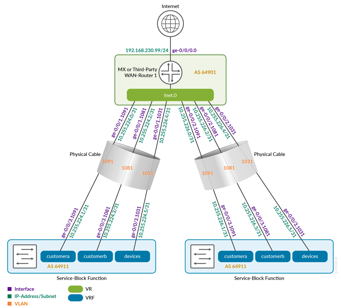
Figure 25 shows how the two service block functions of the fabric would connect to the second WAN router. Notice that we now use the second block of VLANs from each VRF.
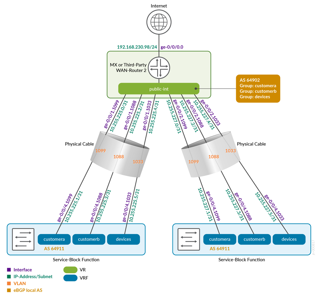
Table 1 displays the full configuration between the core1 and core2 switches, as service block function, and the two WAN routers. You can also see the ASN chosen for eBGP.
| Switch | Switch AS | VRF | Core P2P IP | Core IF | WAN Router | WAN Router P2P IP | WAN Router AS | WAN Router IF | VLAN-ID |
|---|---|---|---|---|---|---|---|---|---|
| core1 | 64911 | customera | 10.255.224.1/31 | ge-0/0/3.1091 | wanrouter1 | 10.255.224.0/31 | 64901 | ge-0/0/1.1091 | 1091 |
| core1 | 64911 | customerb | 10.255.224.3/31 | ge-0/0/3.1081 | wanrouter1 | 10.255.224.2/31 | 64901 | ge-0/0/1.1081 | 1081 |
| core1 | 64911 | devices | 10.255.224.5/31 | ge-0/0/3.1031 | wanrouter1 | 10.255.224.4/31 | 64901 | ge-0/0/1.1031 | 1031 |
| core1 | 64911 | customera | 10.255.225.1/31 | ge-0/0/4.1099 | wanrouter2 | 10.255.225.0/31 | 64902 | ge-0/0/1.1099 | 1099 |
| core1 | 64911 | customerb | 10.255.225.3/31 | ge-0/0/4.1088 | wanrouter2 | 10.255.225.2/31 | 64902 | ge-0/0/1.1088 | 1088 |
| core1 | 64911 | devices | 10.255.225.5/31 | ge-0/0/4.1033 | wanrouter2 | 10.255.225.4/31 | 64902 | ge-0/0/1.1033 | 1033 |
| core2 | 64911 | customera | 10.255.226.1/31 | ge-0/0/3.1091 | wanrouter1 | 10.255.226.0/31 | 64901 | ge-0/0/2.1091 | 1091 |
| core2 | 64911 | customerb | 10.255.226.3/31 | ge-0/0/3.1081 | wanrouter1 | 10.255.226.2/31 | 64901 | ge-0/0/2.1081 | 1081 |
| core2 | 64911 | devices | 10.255.226.5/31 | ge-0/0/3.1031 | wanrouter1 | 10.255.226.4/31 | 64901 | ge-0/0/2.1031 | 1031 |
| core2 | 64911 | customera | 10.255.227.1/31 | ge-0/0/4.1099 | wanrouter2 | 10.255.227.0/31 | 64902 | ge-0/0/2.1099 | 1099 |
| core2 | 64911 | customerb | 10.255.227.3/31 | ge-0/0/4.1088 | wanrouter2 | 10.255.227.2/31 | 64902 | ge-0/0/2.1088 | 1088 |
| core2 | 64911 | devices | 10.255.227.5/31 | ge-0/0/4.1033 | wanrouter2 | 10.255.227.4/31 | 64902 | ge-0/0/2.1033 | 1033 |
The code block below shows the exported version of the switch template used in this fabric. This allows you to review our setup when importing. As you can see, we have a minimum of two VLANs per VRF. Remember that the L3 exit model requires one VLAN per WAN router and VRF).
{
  "additional_config_cmds": [],
  "networks": {
    "vlan1099": {
      "vlan_id": 1099,
      "subnet": "10.99.99.0/24"
    },
    "vlan1088": {
      "vlan_id": 1088,
      "subnet": "10.88.88.0/24"
    },
    "vlan1033": {
      "vlan_id": 1033,
      "subnet": "10.33.33.0/24"
    },
    "vlan1091": {
      "vlan_id": 1091,
      "subnet": "10.99.91.0/24"
    },
    "vlan1081": {
      "vlan_id": 1081,
      "subnet": "10.88.81.0/24"
    },
    "vlan1031": {
      "vlan_id": 1031,
      "subnet": "10.33.31.0/24"
    }
  },
  "port_usages": {
    "vlan1099": {
      "mode": "access",
      "disabled": false,
      "port_network": "vlan1099",
      "voip_network": null,
      "stp_edge": false,
      "mac_auth_protocol": null,
      "all_networks": false,
      "networks": null,
      "port_auth": null,
      "enable_mac_auth": null,
      "mac_auth_only": null,
      "guest_network": null,
      "bypass_auth_when_server_down": null,
      "speed": "auto",
      "duplex": "auto",
      "mac_limit": 0,
      "persist_mac": false,
      "poe_disabled": false,
      "enable_qos": false,
      "storm_control": {},
      "mtu": null,
      "description": "",
      "disable_autoneg": false
    },
    "vlan1088": {
      "mode": "access",
      "disabled": false,
      "port_network": "vlan1088",
      "voip_network": null,
      "stp_edge": false,
      "mac_auth_protocol": null,
      "all_networks": false,
      "networks": null,
      "port_auth": null,
      "enable_mac_auth": null,
      "mac_auth_only": null,
      "guest_network": null,
      "bypass_auth_when_server_down": null,
      "speed": "auto",
      "duplex": "auto",
      "mac_limit": 0,
      "persist_mac": false,
      "poe_disabled": false,
      "enable_qos": false,
      "storm_control": {},
      "mtu": null,
      "description": "",
      "disable_autoneg": false
    },
    "dynamic": {
      "mode": "dynamic",
      "reset_default_when": "link_down",
      "rules": []
    }
  },
  "switch_matching": {
    "enable": true,
    "rules": []
  },
  "switch_mgmt": {
    "config_revert_timer": 10,
    "root_password": "<password>",
    "protect_re": {
      "enabled": false
    },
    "tacacs": {
      "enabled": false
    }
  },
  "mist_nac": {
    "enabled": true,
    "network": null
  },
  "radius_config": {
    "auth_servers": [],
    "acct_servers": [],
    "auth_servers_timeout": 5,
    "auth_servers_retries": 3,
    "fast_dot1x_timers": false,
    "acct_interim_interval": 0,
    "auth_server_selection": "ordered",
    "coa_enabled": false,
    "coa_port": ""
  },
  "vrf_config": {
    "enabled": false
  },
  "remote_syslog": {
    "enabled": false
  },
  "snmp_config": {
    "enabled": false
  },
  "dhcp_snooping": {
    "enabled": false
  },
  "dns_servers": [],
  "dns_suffix": [],
  "ntp_servers": [],
  "acl_policies": [],
  "port_mirroring": {},
  "name": "campus-fabric"
}
Within the Campus Fabric Configuration dialogue, there is a page called Configure Networks. This is where you import your six VLAN’s from the switch template. The resulting configuration is shown in the following figures.
Then you go to each VRF and delete all manual routes you may have. Make sure each VRF has a minimum of two VLAN’s attached as those are used to identify the VRF later.
Core1 Switch Configuration
In this example, the service block function is virtual and co-located on the core switch. Therefore, you must configure the two core switches. The following block of pseudocode describes what you need to configure on the core1 switch:
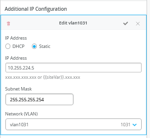
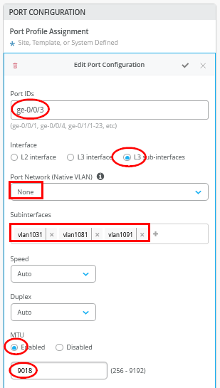
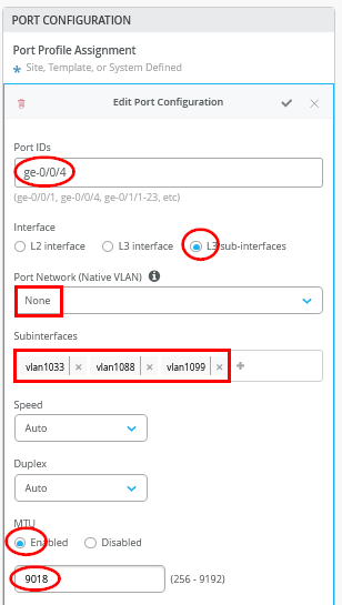
# configure the Additional IP-Subnet 10.255.224.1 255.255.255.254 to Network/VLAN:vlan1091
# configure the Additional IP-Subnet 10.255.224.3 255.255.255.254 to Network/VLAN:vlan1081
# configure the Additional IP-Subnet 10.255.224.5 255.255.255.254 to Network/VLAN:vlan1031
# Then bind these 3 Network/VLANs to Port Interface ge-0/0/3 as L3-Sub-Interfaces with MTU=9018
#
# configure the Additional IP-Subnet 10.255.225.1 255.255.255.254 to Network/VLAN:vlan1099
# configure the Additional IP-Subnet 10.255.225.3 255.255.255.254 to Network/VLAN:vlan1088
# configure the Additional IP-Subnet 10.255.225.5 255.255.255.254 to Network/VLAN:vlan1033
# Then bind these 3 Network/VLANs to Port Interface ge-0/0/4 as L3-Sub-Interfaces with MTU=9018
#
# Enable BGP
# Create an Export policy called 'export-vrfs'
# Add to this export Policy the following Networks as:
# - Add Term w. Name=fabric-all-no-hosts  Prefix=0.0.0.0/0-30  Protocol=None  Then=Accept
# - Add Term w. Name=overlaylo0 Prefix=172.16.192.0/24-32  Protocol=None  Then=Accept
#
# Create an Export policy called 'import-default'
# - Name=default  Prefix=0.0.0.0/0  Protocol=BGP  Action=Accept
#
# Create a BGP Group with:
# - Name=customera0
# - Type=External
# - Network (VLAN)=vlan1091
# - BFD interval=1000
# - Local AS=64911
# - Hold Time=90
# - Set Export=export-vrfs and Import=import-default
# Add also the following Neighbor
# - IP_Address=10.255.224.0  Neighbor_AS=64901  Hold-Time=90
#
# Create a BGP Group with:
# - Name=customerb0
# - Type=External
# - Network (VLAN)=vlan1081
# - BFD interval=1000
# - Local AS=64911
# - Hold Time=90
# - Set Export=export-vrfs and Import=import-default
# Add also the following Neighbor
# - IP_Address=10.255.224.2  Neighbor_AS=64901  Hold-Time=90
#
# Create a BGP Group with:
# - Name=devices0
# - Type=External
# - Network (VLAN)=vlan1031
# - BFD interval=1000
# - Local AS=64911
# - Hold Time=90
# - Set Export=export-vrfs and Import=import-default
# Add also the following Neighbor
# - IP_Address=10.255.224.4  Neighbor_AS=64901  Hold-Time=90
#
# Create a BGP Group with:
# - Name=customera1
# - Type=External
# - Network (VLAN)=vlan1099
# - BFD interval=1000
# - Local AS=64911
# - Hold Time=90
# - Set Export=export-vrfs and Import=import-default
# Add also the following Neighbor
# - IP_Address=10.255.225.0  Neighbor_AS=64902  Hold-Time=90
#
# Create a BGP Group with:
# - Name=customerb1
# - Type=External
# - Network (VLAN)=vlan1088
# - BFD interval=1000
# - Local AS=64911
# - Hold Time=90
# - Set Export=export-vrfs and Import=import-default
# Add also the following Neighbor
# - IP_Address=10.255.225.2  Neighbor_AS=64902  Hold-Time=90
#
# Create a BGP Group with:
# - Name=devices1
# - Type=External
# - Network (VLAN)=vlan1033
# - BFD interval=1000
# - Local AS=64911
# - Hold Time=90
# - Set Export=export-vrfs and Import=import-default
# Add also the following Neighbor
# - IP_Address=10.255.225.4  Neighbor_AS=64902  Hold-Time=90
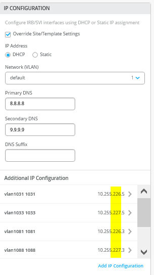
The following screenshots show the previous configuration translated into the Mist GUI. We start with the additional IP configuration. Notice that the VLAN IP addresses do not match the IP addresses that these VLANs had originally in the overlay. This is by design. You must always have the VLAN as a reference back to the VRF.
In the Port Configuration window, you must enable the L3-sub-interfaces and assign the first 3 sub-interfaces defined.
In the second Port Configuration window, towards the other WAN router, assign the second 3 sub-interfaces defined.
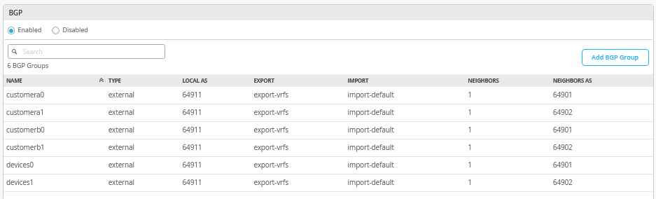
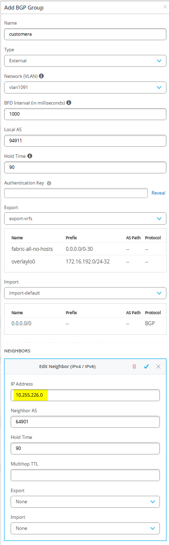
Next, you must enter the entire eBGP configuration with all six peers (three VRFs and two WAN routers. When finished, the overview page should be as shown in Figure 33 .
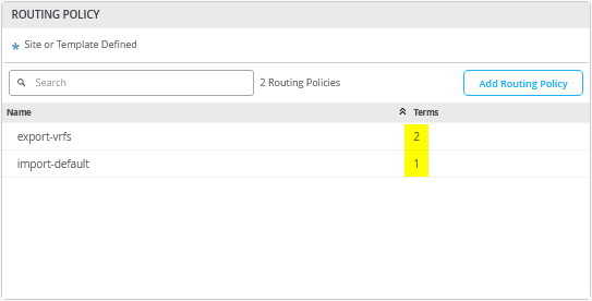
First, you define two routing policies, a summary of which is shown in the above table.
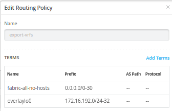
In our example, the export route policies contain the following terms:
- Term=fabric-all-no-hosts — Used to automatically export all routes of a fabric from all configured VRFs and their VLANs. We strip potential P2P links and single host routes. To achieve this, we use the prefix “0.0.0.0/0-30”. Using “0-30” in the prefix is a way of defining “orlonger” in the Junos OS.
- Term=overlaylo0 — Used to export the overlay loopback IP addresses (for DHCP relay usage) down to the host IP level as they are usually individually assigned to lo0.x. To achieve this, we use 172.16.192.0/24-32 as we here need to go down towards host level which we do not do in the above statement.
If desired, you can simplify the rule set by using a single term such as “0.0.0.0/0-32,” which exports all routes—including those for individual clients in the fabric, represented by their host IP addresses. This approach can also be useful for debugging, as examining the AS-Path information on the WAN router will reveal which EVPN fabric switch is announcing a given host IP.
The downside, however, is that this approach may result in a large number of routes being exchanged with the WAN router, whereas the default setting of “0.0.0.0/0-30” limits route sharing to prefixes associated only with the configured VLANs.
10.99.99.0/24      *[BGP/170] 00:06:46, localpref 100, from 10.255.226.1
                      AS path: 64911 65001 65004 65005 I, validation-state: unverified
                       to 10.255.224.1 via ge-0/0/2.1091
                       to 10.255.226.1 via ge-0/0/3.1091
                    >  to 10.255.225.1 via ge-7/0/2.1099
                       to 10.255.227.1 via ge-7/0/3.1099
                    [BGP/170] 00:06:50, localpref 100
                      AS path: 64911 65002 65004 65005 I, validation-state: unverified
                    >  to 10.255.224.1 via ge-0/0/2.1091
                    [BGP/170] 00:12:38, localpref 100
                      AS path: 64911 65002 65004 65005 I, validation-state: unverified
                    >  to 10.255.225.1 via ge-7/0/2.1099
                    [BGP/170] 00:06:46, localpref 100
                      AS path: 64911 65001 65004 65005 I, validation-state: unverified
                    >  to 10.255.227.1 via ge-7/0/3.1099
10.99.99.99/32     *[BGP/170] 00:00:14, localpref 100, from 10.255.224.1
                      AS path: 64911 65002 65003 65006 I, validation-state: unverified
                       to 10.255.224.1 via ge-0/0/2.1091
                       to 10.255.226.1 via ge-0/0/3.1091
                    >  to 10.255.225.1 via ge-7/0/2.1099
                       to 10.255.227.1 via ge-7/0/3.1099
                    [BGP/170] 00:01:33, localpref 100
                      AS path: 64911 65002 65003 65006 I, validation-state: unverified
                    >  to 10.255.225.1 via ge-7/0/2.1099
                    [BGP/170] 00:00:14, localpref 100
                      AS path: 64911 65001 65003 65006 I, validation-state: unverified
                    >  to 10.255.226.1 via ge-0/0/3.1091
                    [BGP/170] 00:00:14, localpref 100
                      AS path: 64911 65001 65003 65006 I, validation-state: unverified
                    >  to 10.255.227.1 via ge-7/0/3.1099
The import policy imports the default route from the WAN router.
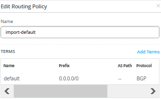
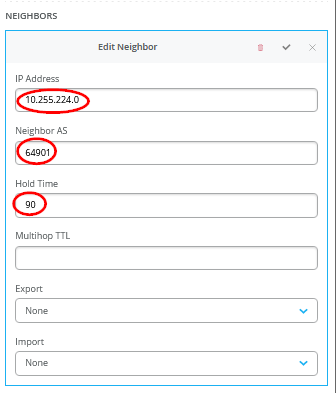
Figure 35 shows the configuration of a single BGP peering entry with the required entries called out.
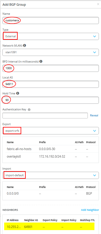
You must also define the WAN router as a BGP neighbor.
You may see a warning message as shown in Figure 36 . It is safe to ignore those.
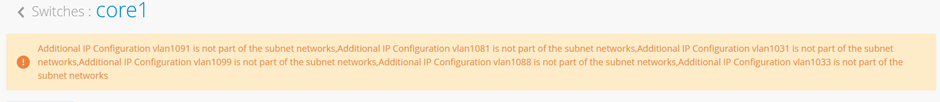
- The messages mentioned above appear because we are reusing overlay VLANs—already assigned to VRFs—for underlay BGP peering with the WAN router. This can be avoided by using dedicated VLANs for BGP peering that are not part of the fabric's VRF configuration. To do so, a local VRF setup similar to the “L2 Exit with Transport VLAN” approach is required. This involves manually adding the BGP peering VLANs to each VRF, along with the overlay VLANs configured through the standard fabric configuration dialogue.
- While this method eliminates the false-positive error messages, it comes with a trade-off: every time a new VLAN is added to the fabric, you'll need to manually update each service block to include the new VLAN in the custom local VRF configuration.
- In contrast, the method used in this JVD-E avoids such error-prone reconfiguration. You simply add the new VLAN to the switch template and configure it through the fabric dialogue. The service block configuration remains unchanged and will automatically export the new VLAN's routes based on the export filter configuration shown above.
Core2 Switch Configuration
The following pseudocode represents the configuration you must apply to the core2 switch:
# configure the Additional IP-Subnet 10.255.226.1 255.255.255.254 to Network/VLAN:vlan1091
# configure the Additional IP-Subnet 10.255.226.3 255.255.255.254 to Network/VLAN:vlan1081
# configure the Additional IP-Subnet 10.255.226.5 255.255.255.254 to Network/VLAN:vlan1031
# Then bind these 3 Network/VLANs to Port Interface ge-0/0/3 as L3-Sub-Interfaces with MTU=9018
#
# configure the Additional IP-Subnet 10.255.227.1 255.255.255.254 to Network/VLAN:vlan1099
# configure the Additional IP-Subnet 10.255.227.3 255.255.255.254 to Network/VLAN:vlan1088
# configure the Additional IP-Subnet 10.255.227.5 255.255.255.254 to Network/VLAN:vlan1033
# Then bind these 3 Network/VLANs to Port Interface ge-0/0/4 as L3-Sub-Interfaces with MTU=9018
#
# Enable BGP
# Create an Export policy called 'export-vrfs'
# Add to this export Policy the following Networks as:
# - Add Term w. Name=fabric-all-no-hosts  Prefix=0.0.0.0/0-30  Protocol=None  Then=Accept
# - Add Term w. Name=overlaylo0 Prefix=172.16.192.0/24-32  Protocol=None  Then=Accept
#
# Create an Export policy called 'import-default'
# - Name=default  Prefix=0.0.0.0/0  Protocol=BGP  Action=Accept
#
# Create a BGP Group with:
# - Name=customera0
# - Type=External
# - Network (VLAN)=vlan1091
# - BFD interval=1000
# - Local AS=64911
# - Hold Time=90
# - Set Export=export-vrfs and Import=import-default
# Add also the following Neighbor
# - IP_Address=10.255.226.0  Neighbor_AS=64901  Hold-Time=90
#
# Create a BGP Group with:
# - Name=customerb0
# - Type=External
# - Network (VLAN)=vlan1081
# - BFD interval=1000
# - Local AS=64911
# - Hold Time=90
# - Set Export=export-vrfs and Import=import-default
# Add also the following Neighbor
# - IP_Address=10.255.226.2  Neighbor_AS=64901  Hold-Time=90
#
# Create a BGP Group with:
# - Name=devices0
# - Type=External
# - Network (VLAN)=vlan1031
# - BFD interval=1000
# - Local AS=64911
# - Hold Time=90
# - Set Export=export-vrfs and Import=import-default
# Add also the following Neighbor
# - IP_Address=10.255.226.4  Neighbor_AS=64901  Hold-Time=90
#
# Create a BGP Group with:
# - Name=customera1
# - Type=External
# - Network (VLAN)=vlan1099
# - BFD interval=1000
# - Local AS=64911
# - Hold Time=90
# - Set Export=export-vrfs and Import=import-default
# Add also the following Neighbor
# - IP_Address=10.255.227.0  Neighbor_AS=64902  Hold-Time=90
#
# Create a BGP Group with:
# - Name=customerb1
# - Type=External
# - Network (VLAN)=vlan1088
# - BFD interval=1000
# - Local AS=64911
# - Hold Time=90
# - Set Export=export-vrfs and Import=import-default
# Add also the following Neighbor
# - IP_Address=10.255.227.2  Neighbor_AS=64902  Hold-Time=90
#
# Create a BGP Group with:
# - Name=devices1
# - Type=External
# - Network (VLAN)=vlan1033
# - BFD interval=1000
# - Local AS=64911
# - Hold Time=90
# - Set Export=export-vrfs and Import=import-default
# Add also the following Neighbor
# - IP_Address=10.255.227.4  Neighbor_AS=64902  Hold-Time=90
Aside from the P2P subnets and the BGP neighbours, the configuration on the core2 switch is the same as the configuration on the core1 switch.
Juniper MX as a WAN Router
The following several code blocks show the Junos OS CLI configuration of the P2P interfaces, the entire eBGP config with all BGP neighbours, and all import and export route policies for each WAN router. You may need to add default routes and interfaces to complete the configuration because those need to be signalled to the fabric but we don’t know how your device gets to know those.
CLI configuration for the first WAN router:
set system host-name wanrouter1
#
delete interfaces ge-0/0/1
set interfaces ge-0/0/1 flexible-vlan-tagging
set interfaces ge-0/0/1 mtu 9014
set interfaces ge-0/0/1 unit 1091 description vlan1091
set interfaces ge-0/0/1 unit 1091 vlan-id 1091
set interfaces ge-0/0/1 unit 1091 family inet address 10.255.224.0/31
set interfaces ge-0/0/1 unit 1081 description vlan1081
set interfaces ge-0/0/1 unit 1081 vlan-id 1081
set interfaces ge-0/0/1 unit 1081 family inet address 10.255.224.2/31
set interfaces ge-0/0/1 unit 1031 description vlan1031
set interfaces ge-0/0/1 unit 1031 vlan-id 1031
set interfaces ge-0/0/1 unit 1031 family inet address 10.255.224.4/31
#
delete interfaces ge-0/0/2
set interfaces ge-0/0/2 flexible-vlan-tagging
set interfaces ge-0/0/2 mtu 9014
set interfaces ge-0/0/2 unit 1091 description vlan1091
set interfaces ge-0/0/2 unit 1091 vlan-id 1091
set interfaces ge-0/0/2 unit 1091 family inet address 10.255.226.0/31
set interfaces ge-0/0/2 unit 1081 description vlan1081
set interfaces ge-0/0/2 unit 1081 vlan-id 1081
set interfaces ge-0/0/2 unit 1081 family inet address 10.255.226.2/31
set interfaces ge-0/0/2 unit 1031 description vlan1031
set interfaces ge-0/0/2 unit 1031 vlan-id 1031
set interfaces ge-0/0/2 unit 1031 family inet address 10.255.226.4/31
#
# needed in and export policy
delete policy-options
set policy-options policy-statement fabric term 1 from protocol bgp
set policy-options policy-statement fabric term 1 from route-filter 0.0.0.0/0 orlonger
set policy-options policy-statement fabric term 1 then accept
set policy-options policy-statement fabric term 2 then reject
set policy-options policy-statement internet term 1 from protocol static
set policy-options policy-statement internet term 1 from route-filter 0.0.0.0/0 exact
set policy-options policy-statement internet term 1 then accept
set policy-options policy-statement internet term 2 then reject
#
delete routing-instances public-int
set routing-instances public-int instance-type virtual-router
set routing-instances public-int interface ge-0/0/1.1091
set routing-instances public-int interface ge-0/0/1.1081
set routing-instances public-int interface ge-0/0/1.1031
set routing-instances public-int interface ge-0/0/2.1091
set routing-instances public-int interface ge-0/0/2.1081
set routing-instances public-int interface ge-0/0/2.1031
#
delete routing-instances public-int protocols bgp group customera
set routing-instances public-int protocols bgp group customera type external
set routing-instances public-int protocols bgp group customera family inet unicast
set routing-instances public-int protocols bgp group customera multipath multiple-as
set routing-instances public-int protocols bgp group customera local-as 64901
set routing-instances public-int protocols bgp group customera hold-time 90
set routing-instances public-int protocols bgp group customera import fabric
set routing-instances public-int protocols bgp group customera export internet
set routing-instances public-int protocols bgp group customera bfd-liveness-detection minimum-interval 1000
set routing-instances public-int protocols bgp group customera bfd-liveness-detection multiplier 3
set routing-instances public-int protocols bgp group customera bfd-liveness-detection session-mode automatic
set routing-instances public-int protocols bgp group customera neighbor 10.255.224.1 peer-as 64911
set routing-instances public-int protocols bgp group customera neighbor 10.255.226.1 peer-as 64911
#
delete routing-instances public-int protocols bgp group customerb
set routing-instances public-int protocols bgp group customerb type external
set routing-instances public-int protocols bgp group customerb family inet unicast
set routing-instances public-int protocols bgp group customerb multipath multiple-as
set routing-instances public-int protocols bgp group customerb local-as 64901
set routing-instances public-int protocols bgp group customerb hold-time 90
set routing-instances public-int protocols bgp group customerb import fabric
set routing-instances public-int protocols bgp group customerb export internet
set routing-instances public-int protocols bgp group customerb bfd-liveness-detection minimum-interval 1000
set routing-instances public-int protocols bgp group customerb bfd-liveness-detection multiplier 3
set routing-instances public-int protocols bgp group customerb bfd-liveness-detection session-mode automatic
set routing-instances public-int protocols bgp group customerb neighbor 10.255.224.3 peer-as 64911
set routing-instances public-int protocols bgp group customerb neighbor 10.255.226.3 peer-as 64911
#
delete routing-instances public-int protocols bgp group devices
set routing-instances public-int protocols bgp group devices type external
set routing-instances public-int protocols bgp group devices family inet unicast
set routing-instances public-int protocols bgp group devices multipath multiple-as
set routing-instances public-int protocols bgp group devices local-as 64901
set routing-instances public-int protocols bgp group devices hold-time 90
set routing-instances public-int protocols bgp group devices import fabric
set routing-instances public-int protocols bgp group devices export internet
set routing-instances public-int protocols bgp group devices bfd-liveness-detection minimum-interval 1000
set routing-instances public-int protocols bgp group devices bfd-liveness-detection multiplier 3
set routing-instances public-int protocols bgp group devices bfd-liveness-detection session-mode automatic
set routing-instances public-int protocols bgp group devices neighbor 10.255.224.5 peer-as 64911
set routing-instances public-int protocols bgp group devices neighbor 10.255.226.5 peer-as 64911
Configuration for the second WAN router:
set system host-name wanrouter2
#
delete interfaces ge-0/0/1
set interfaces ge-0/0/1 flexible-vlan-tagging
set interfaces ge-0/0/1 mtu 9014
set interfaces ge-0/0/1 unit 1099 description vlan1099
set interfaces ge-0/0/1 unit 1099 vlan-id 1099
set interfaces ge-0/0/1 unit 1099 family inet address 10.255.225.0/31
set interfaces ge-0/0/1 unit 1088 description vlan1088
set interfaces ge-0/0/1 unit 1088 vlan-id 1088
set interfaces ge-0/0/1 unit 1088 family inet address 10.255.225.2/31
set interfaces ge-0/0/1 unit 1033 description vlan1033
set interfaces ge-0/0/1 unit 1033 vlan-id 1033
set interfaces ge-0/0/1 unit 1033 family inet address 10.255.225.4/31
#
delete interfaces ge-0/0/2
set interfaces ge-0/0/2 flexible-vlan-tagging
set interfaces ge-0/0/2 mtu 9014
set interfaces ge-0/0/2 unit 1099 description vlan1099
set interfaces ge-0/0/2 unit 1099 vlan-id 1099
set interfaces ge-0/0/2 unit 1099 family inet address 10.255.227.0/31
set interfaces ge-0/0/2 unit 1088 description vlan1088
set interfaces ge-0/0/2 unit 1088 vlan-id 1088
set interfaces ge-0/0/2 unit 1088 family inet address 10.255.227.2/31
set interfaces ge-0/0/2 unit 1033 description vlan1033
set interfaces ge-0/0/2 unit 1033 vlan-id 1033
set interfaces ge-0/0/2 unit 1033 family inet address 10.255.227.4/31
#
# needed in and export policy
delete policy-options
set policy-options policy-statement fabric term 1 from protocol bgp
set policy-options policy-statement fabric term 1 from route-filter 0.0.0.0/0 orlonger
set policy-options policy-statement fabric term 1 then accept
set policy-options policy-statement fabric term 2 then reject
set policy-options policy-statement internet term 1 from protocol static
set policy-options policy-statement internet term 1 from route-filter 0.0.0.0/0 exact
set policy-options policy-statement internet term 1 then accept
set policy-options policy-statement internet term 2 then reject
#
delete routing-instances public-int
set routing-instances public-int instance-type virtual-router
set routing-instances public-int interface ge-0/0/1.1099
set routing-instances public-int interface ge-0/0/1.1088
set routing-instances public-int interface ge-0/0/1.1033
set routing-instances public-int interface ge-0/0/2.1099
set routing-instances public-int interface ge-0/0/2.1088
set routing-instances public-int interface ge-0/0/2.1033
#
delete routing-instances public-int protocols bgp group customera
set routing-instances public-int protocols bgp group customera type external
set routing-instances public-int protocols bgp group customera family inet unicast
set routing-instances public-int protocols bgp group customera multipath multiple-as
set routing-instances public-int protocols bgp group customera local-as 64902
set routing-instances public-int protocols bgp group customera hold-time 90
set routing-instances public-int protocols bgp group customera import fabric
set routing-instances public-int protocols bgp group customera export internet
set routing-instances public-int protocols bgp group customera bfd-liveness-detection minimum-interval 1000
set routing-instances public-int protocols bgp group customera bfd-liveness-detection multiplier 3
set routing-instances public-int protocols bgp group customera bfd-liveness-detection session-mode automatic
set routing-instances public-int protocols bgp group customera neighbor 10.255.225.1 peer-as 64911
set routing-instances public-int protocols bgp group customera neighbor 10.255.227.1 peer-as 64911
#
delete routing-instances public-int protocols bgp group customerb
set routing-instances public-int protocols bgp group customerb type external
set routing-instances public-int protocols bgp group customerb family inet unicast
set routing-instances public-int protocols bgp group customerb multipath multiple-as
set routing-instances public-int protocols bgp group customerb local-as 64902
set routing-instances public-int protocols bgp group customerb hold-time 90
set routing-instances public-int protocols bgp group customerb import fabric
set routing-instances public-int protocols bgp group customerb export internet
set routing-instances public-int protocols bgp group customerb bfd-liveness-detection minimum-interval 1000
set routing-instances public-int protocols bgp group customerb bfd-liveness-detection multiplier 3
set routing-instances public-int protocols bgp group customerb bfd-liveness-detection session-mode automatic
set routing-instances public-int protocols bgp group customerb neighbor 10.255.225.3 peer-as 64911
set routing-instances public-int protocols bgp group customerb neighbor 10.255.227.3 peer-as 64911
#
delete routing-instances public-int protocols bgp group devices
set routing-instances public-int protocols bgp group devices type external
set routing-instances public-int protocols bgp group devices family inet unicast
set routing-instances public-int protocols bgp group devices multipath multiple-as
set routing-instances public-int protocols bgp group devices local-as 64902
set routing-instances public-int protocols bgp group devices hold-time 90
set routing-instances public-int protocols bgp group devices import fabric
set routing-instances public-int protocols bgp group devices export internet
set routing-instances public-int protocols bgp group devices bfd-liveness-detection minimum-interval 1000
set routing-instances public-int protocols bgp group devices bfd-liveness-detection multiplier 3
set routing-instances public-int protocols bgp group devices bfd-liveness-detection session-mode automatic
set routing-instances public-int protocols bgp group devices neighbor 10.255.225.5 peer-as 64911
set routing-instances public-int protocols bgp group devices neighbor 10.255.227.5 peer-as 64911
You can use the following CLI commands to assist with debugging on WAN router1.
root@wanrouter1> show bgp summary
Threading mode: BGP I/O
Default eBGP mode: advertise - accept, receive - accept
Groups: 3 Peers: 6 Down peers: 0
Peer                     AS      InPkt     OutPkt    OutQ   Flaps Last Up/Dwn State|#Active/Received/Accepted/Damped...
10.255.224.1          64911         30         27       0       0       11:37 Establ
  public-int.inet.0: 2/2/2/0
10.255.224.3          64911         29         27       0       0       11:31 Establ
  public-int.inet.0: 2/2/2/0
10.255.224.5          64911         29         27       0       0       11:37 Establ
  public-int.inet.0: 1/1/1/0
10.255.226.1          64911         30         27       0       0       11:30 Establ
  public-int.inet.0: 2/2/2/0
10.255.226.3          64911         30         27       0       0       11:39 Establ
  public-int.inet.0: 2/2/2/0
10.255.226.5          64911         29         27       0       0       11:38 Establ
  public-int.inet.0: 1/1/1/0
.
root@wanrouter1> show route table public-int.inet.0
.
public-int.inet.0: 23 destinations, 25 routes (23 active, 0 holddown, 0 hidden)
+ = Active Route, - = Last Active, * = Both
0.0.0.0/0          *[Static/5] 00:00:42
                    >  to 192.168.230.1 via ge-0/0/0.0
10.88.88.0/24      *[BGP/170] 00:11:47, localpref 100
                      AS path: 64911 65002 65003 65005 I, validation-state: unverified
                       to 10.255.224.3 via ge-0/0/1.1081
                    >  to 10.255.226.3 via ge-0/0/2.1081
                    [BGP/170] 00:11:47, localpref 100
                      AS path: 64911 65001 65003 65005 I, validation-state: unverified
                    >  to 10.255.224.3 via ge-0/0/1.1081
10.99.99.0/24      *[BGP/170] 00:11:46, localpref 100, from 10.255.224.1
                      AS path: 64911 65001 65003 65005 I, validation-state: unverified
                       to 10.255.224.1 via ge-0/0/1.1091
                    >  to 10.255.226.1 via ge-0/0/2.1091
                    [BGP/170] 00:11:46, localpref 100
                      AS path: 64911 65002 65003 65005 I, validation-state: unverified
                    >  to 10.255.226.1 via ge-0/0/2.1091
10.255.224.0/31    *[Direct/0] 00:22:31
                    >  via ge-0/0/1.1091
10.255.224.0/32    *[Local/0] 00:22:31
                       Local via ge-0/0/1.1091
10.255.224.2/31    *[Direct/0] 00:22:31
                    >  via ge-0/0/1.1081
10.255.224.2/32    *[Local/0] 00:22:31
                       Local via ge-0/0/1.1081
10.255.224.4/31    *[Direct/0] 00:22:31
                    >  via ge-0/0/1.1031
10.255.224.4/32    *[Local/0] 00:22:31
                       Local via ge-0/0/1.1031
10.255.226.0/31    *[Direct/0] 00:22:31
                    >  via ge-0/0/2.1091
10.255.226.0/32    *[Local/0] 00:22:31
                       Local via ge-0/0/2.1091
10.255.226.2/31    *[Direct/0] 00:22:31
                    >  via ge-0/0/2.1081
10.255.226.2/32    *[Local/0] 00:22:31
                       Local via ge-0/0/2.1081
10.255.226.4/31    *[Direct/0] 00:22:31
                    >  via ge-0/0/2.1031
10.255.226.4/32    *[Local/0] 00:22:31
                       Local via ge-0/0/2.1031
172.16.193.1/32    *[BGP/170] 00:11:53, localpref 100
                      AS path: 64911 I, validation-state: unverified
                    >  to 10.255.224.1 via ge-0/0/1.1091
172.16.193.2/32    *[BGP/170] 00:11:46, localpref 100
                      AS path: 64911 I, validation-state: unverified
                    >  to 10.255.226.1 via ge-0/0/2.1091
172.16.194.1/32    *[BGP/170] 00:11:47, localpref 100
                      AS path: 64911 I, validation-state: unverified
                    >  to 10.255.224.3 via ge-0/0/1.1081
172.16.194.2/32    *[BGP/170] 00:11:55, localpref 100
                      AS path: 64911 I, validation-state: unverified
                    >  to 10.255.226.3 via ge-0/0/2.1081
172.16.195.1/32    *[BGP/170] 00:11:53, localpref 100
                      AS path: 64911 I, validation-state: unverified
                    >  to 10.255.224.5 via ge-0/0/1.1031
172.16.195.2/32    *[BGP/170] 00:11:54, localpref 100
                      AS path: 64911 I, validation-state: unverified
                    >  to 10.255.226.5 via ge-0/0/2.1031
192.168.230.0/24   *[Direct/0] 00:01:08
                    >  via ge-0/0/0.0
192.168.230.99/32  *[Local/0] 00:01:08
                       Local via ge-0/0/0.0
You can use the following CLI commands to assist with debugging on WAN router2.
root@wanrouter2> show bgp summary
Threading mode: BGP I/O
Default eBGP mode: advertise - accept, receive - accept
Groups: 3 Peers: 6 Down peers: 0
Peer                     AS      InPkt     OutPkt    OutQ   Flaps Last Up/Dwn State|#Active/Received/Accepted/Damped...
10.255.225.1          64911         36         33       0       0       14:29 Establ
  public-int.inet.0: 2/2/2/0
10.255.225.3          64911         36         33       0       0       14:21 Establ
  public-int.inet.0: 2/2/2/0
10.255.225.5          64911         35         34       0       0       14:31 Establ
  public-int.inet.0: 1/1/1/0
10.255.227.1          64911         36         34       0       0       14:35 Establ
  public-int.inet.0: 2/2/2/0
10.255.227.3          64911         36         34       0       0       14:35 Establ
  public-int.inet.0: 2/2/2/0
10.255.227.5          64911         34         33       0       0       14:21 Establ
  public-int.inet.0: 1/1/1/0
.
root@wanrouter2> show route table public-int.inet.0
.
public-int.inet.0: 23 destinations, 25 routes (23 active, 0 holddown, 0 hidden)
+ = Active Route, - = Last Active, * = Both
0.0.0.0/0          *[Static/5] 00:00:24
                    >  to 192.168.230.1 via ge-0/0/0.0
10.88.88.0/24      *[BGP/170] 00:14:35, localpref 100
                      AS path: 64911 65002 65003 65005 I, validation-state: unverified
                       to 10.255.225.3 via ge-0/0/1.1088
                    >  to 10.255.227.3 via ge-0/0/2.1088
                    [BGP/170] 00:14:35, localpref 100
                      AS path: 64911 65001 65003 65005 I, validation-state: unverified
                    >  to 10.255.225.3 via ge-0/0/1.1088
10.99.99.0/24      *[BGP/170] 00:14:43, localpref 100
                      AS path: 64911 65002 65003 65005 I, validation-state: unverified
                       to 10.255.225.1 via ge-0/0/1.1099
                    >  to 10.255.227.1 via ge-0/0/2.1099
                    [BGP/170] 00:14:43, localpref 100
                      AS path: 64911 65001 65003 65005 I, validation-state: unverified
                    >  to 10.255.225.1 via ge-0/0/1.1099
10.255.225.0/31    *[Direct/0] 00:25:19
                    >  via ge-0/0/1.1099
10.255.225.0/32    *[Local/0] 00:25:19
                       Local via ge-0/0/1.1099
10.255.225.2/31    *[Direct/0] 00:25:19
                    >  via ge-0/0/1.1088
10.255.225.2/32    *[Local/0] 00:25:19
                       Local via ge-0/0/1.1088
10.255.225.4/31    *[Direct/0] 00:25:19
                    >  via ge-0/0/1.1033
10.255.225.4/32    *[Local/0] 00:25:19
                       Local via ge-0/0/1.1033
10.255.227.0/31    *[Direct/0] 00:25:19
                    >  via ge-0/0/2.1099
10.255.227.0/32    *[Local/0] 00:25:19
                       Local via ge-0/0/2.1099
10.255.227.2/31    *[Direct/0] 00:25:19
                    >  via ge-0/0/2.1088
10.255.227.2/32    *[Local/0] 00:25:19
                       Local via ge-0/0/2.1088
10.255.227.4/31    *[Direct/0] 00:25:19
                    >  via ge-0/0/2.1033
10.255.227.4/32    *[Local/0] 00:25:19
                       Local via ge-0/0/2.1033
172.16.193.1/32    *[BGP/170] 00:14:43, localpref 100
                      AS path: 64911 I, validation-state: unverified
                    >  to 10.255.225.1 via ge-0/0/1.1099
172.16.193.2/32    *[BGP/170] 00:14:49, localpref 100
                      AS path: 64911 I, validation-state: unverified
                    >  to 10.255.227.1 via ge-0/0/2.1099
172.16.194.1/32    *[BGP/170] 00:14:35, localpref 100
                      AS path: 64911 I, validation-state: unverified
                    >  to 10.255.225.3 via ge-0/0/1.1088
172.16.194.2/32    *[BGP/170] 00:14:49, localpref 100
                      AS path: 64911 I, validation-state: unverified
                    >  to 10.255.227.3 via ge-0/0/2.1088
172.16.195.1/32    *[BGP/170] 00:14:45, localpref 100
                      AS path: 64911 I, validation-state: unverified
                    >  to 10.255.225.5 via ge-0/0/1.1033
172.16.195.2/32    *[BGP/170] 00:14:35, localpref 100
                      AS path: 64911 I, validation-state: unverified
                    >  to 10.255.227.5 via ge-0/0/2.1033
192.168.230.0/24   *[Direct/0] 00:00:24
                    >  via ge-0/0/0.0
192.168.230.98/32  *[Local/0] 00:00:24
                       Local via ge-0/0/0.0
Juniper SRX Series Firewall as WAN Router
The following example table and configurations show the differences between using an SRX Series Firewall in cluster mode and an MX router as the WAN router. On the fabric side, only the interface names of the SRX cluster change from the MX router configuration. Because the SRX Series Firewall runs in active/active cluster mode, there is only a single WAN router configuration and a single ASN to consider. That single configuration also includes cluster management and trust-zone management commands that are not present in a similar MX router-based configuration.
This SRX Series Firewall-based approach is less complicated than configuring redundant ethernet (reth) interfaces and link aggregation groups (LAG) on the MX router. In addition, there is need for additional CLI on the fabric side to insert virtual gateways, and so on.
Preventing Potential Asymmetric Route Issues Using As-Path Prepending
When stateful firewalls are connected to a fabric, there's a potential risk of asymmetric routing. Consider the following scenario: a client outside the fabric initiates a TCP connection to a client inside the fabric via the WAN router. During the initial TCP three-way handshake, the SYN packet is handled by the first WAN router. However, the SYN-ACK response from the fabric client may be processed by the second WAN router, since both routers advertise the same default route into the fabric. The fabric, unaware of any preference, may choose the second WAN router due to ECMP load balancing or other internal mechanisms. If the stateful firewalls (acting as WAN routers) do not share session state, the second WAN router may drop the return packet, as it has no record of the session initiated through the first WAN router.
To prevent this issue, you can make the default route advertised by the second WAN router less preferred, ensuring that return traffic, under normal conditions, is directed to the first WAN router. In BGP, this is typically achieved through AS-Path prepending, which makes the route to the second WAN router less attractive. In the SRX cluster configuration shown below, we use two export filters toward the fabric—one of which includes AS-Path prepending for the default route. These filters are then applied to the fabric neighbours based on which WAN router should be less preferred.
set policy-options policy-statement internet0 term 1 from protocol static
set policy-options policy-statement internet0 term 1 from route-filter 0.0.0.0/0 exact
set policy-options policy-statement internet0 term 1 then accept
set policy-options policy-statement internet0 term 2 then reject
set policy-options policy-statement internet1 term 1 from protocol static
set policy-options policy-statement internet1 term 1 from route-filter 0.0.0.0/0 exact
set policy-options policy-statement internet1 term 1 then as-path-prepend "64999 64999"
set policy-options policy-statement internet1 term 1 then accept
set policy-options policy-statement internet1 term 2 then reject
Once BGP peering with the fabric is established, you can verify the default routes received by the fabric. In the example below, core1-switch serves as the service block function.
root@core1> show route aspath-regex ".* 64901 .*"
.
devices.inet.0: 13 destinations, 19 routes (13 active, 0 holddown, 0 hidden)
@ = Routing Use Only, # = Forwarding Use Only
+ = Active Route, - = Last Active, * = Both
.
0.0.0.0/0          *[BGP/170] 00:00:24, localpref 100
                      AS path: 64901 I, validation-state: unverified
                    >  to 10.255.224.4 via ge-0/0/5.1031
                    [BGP/170] 00:00:24, localpref 100
                      AS path: 64999 64999 64901 I, validation-state: unverified
                    >  to 10.255.225.4 via ge-0/0/6.1033
.
customerb.inet.0: 14 destinations, 20 routes (14 active, 0 holddown, 0 hidden)
@ = Routing Use Only, # = Forwarding Use Only
+ = Active Route, - = Last Active, * = Both
.
0.0.0.0/0          *[BGP/170] 00:00:24, localpref 100
                      AS path: 64901 I, validation-state: unverified
                    >  to 10.255.224.2 via ge-0/0/5.1081
                    [BGP/170] 00:00:24, localpref 100
                      AS path: 64999 64999 64901 I, validation-state: unverified
                    >  to 10.255.225.2 via ge-0/0/6.1088
.
customera.inet.0: 14 destinations, 20 routes (14 active, 0 holddown, 0 hidden)
@ = Routing Use Only, # = Forwarding Use Only
+ = Active Route, - = Last Active, * = Both
.
0.0.0.0/0          *[BGP/170] 00:00:24, localpref 100
                      AS path: 64901 I, validation-state: unverified
                    >  to 10.255.224.0 via ge-0/0/5.1091
                    [BGP/170] 00:00:24, localpref 100
                      AS path: 64999 64999 64901 I, validation-state: unverified
                    >  to 10.255.225.0 via ge-0/0/6.1099
.
A similar approach is recommended for the fabric configuration to ensure uplink traffic consistently prefers one WAN router. This is achieved by making the routes advertised to the second WAN router less attractive using AS-Path prepending. Unlike the MX router example above, which uses a shared “export-vrfs” filter, we now use two separate filters—“export-vrfs0” and “export-vrfs1”—as shown in Figure 39 .
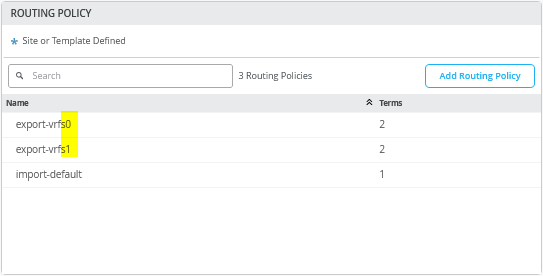
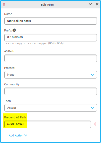
They may look the same but all statements in “export-vrfs1” have AP-Path prepending configured as in Figure 40.
Once BGP peering with the SRX cluster is established, verify that the AS-Path prepends in the fabric are visible, as shown in the example below from the SRX cluster. Start by checking the configuration on the fabric’s service block function—in this case, core1-switch.
root@core1> show configuration | display set | match export-vrf
set groups top policy-options policy-statement export-vrfs0 term 01_fabric-all-no-hosts from route-filter-list 0-0-0-0_0-30
set groups top policy-options policy-statement export-vrfs0 term 01_fabric-all-no-hosts then accept
set groups top policy-options policy-statement export-vrfs0 term 02_overlaylo0 from route-filter-list 172-16-192-0_24-32
set groups top policy-options policy-statement export-vrfs0 term 02_overlaylo0 then accept
set groups top policy-options policy-statement export-vrfs1 term 01_fabric-all-no-hosts from route-filter-list 0-0-0-0_0-30
set groups top policy-options policy-statement export-vrfs1 term 01_fabric-all-no-hosts then as-path-prepend "64998 64998"
set groups top policy-options policy-statement export-vrfs1 term 01_fabric-all-no-hosts then accept
set groups top policy-options policy-statement export-vrfs1 term 02_overlaylo0 from route-filter-list 172-16-192-0_24-32
set groups top policy-options policy-statement export-vrfs1 term 02_overlaylo0 then as-path-prepend "64998 64998"
set groups top policy-options policy-statement export-vrfs1 term 02_overlaylo0 then accept
set groups top routing-instances devices protocols bgp group devices0 export export-vrfs0
set groups top routing-instances devices protocols bgp group devices1 export export-vrfs1
set groups top routing-instances customerb protocols bgp group customerb0 export export-vrfs0
set groups top routing-instances customerb protocols bgp group customerb1 export export-vrfs1
set groups top routing-instances customera protocols bgp group customera0 export export-vrfs0
set groups top routing-instances customera protocols bgp group customera1 export export-vrfs1
Then, we also ensure that we receive those routes according to our configuration on the SRX cluster as in below example.
# neighbor-IP:10.255.224.1 which is assigned on srx-cluster to vrf:customera interface ge-0/0/2.1091
root@srx1> show route receive-protocol bgp 10.255.224.1
.
public-int.inet.0: 46 destinations, 101 routes (46 active, 0 holddown, 0 hidden)
  Prefix                  Nexthop              MED     Lclpref    AS path
* 10.99.91.0/24           10.255.224.1                            64911 65002 65004 65005 I
* 10.99.99.0/24           10.255.224.1                            64911 65002 65004 65005 I
* 172.16.192.1/32         10.255.224.1                            64911 65002 65004 65005 I
* 172.16.192.4/32         10.255.224.1                            64911 65002 65004 65006 I
* 172.16.192.7/32         10.255.224.1                            64911 I
  172.16.192.10/32        10.255.224.1                            64911 65002 65004 65001 I
.
# neighbor-IP:10.255.226.1 which is assigned on srx-cluster to vrf:customera interface ge-0/0/3.1091
root@srx1> show route receive-protocol bgp 10.255.226.1
.
public-int.inet.0: 46 destinations, 101 routes (46 active, 0 holddown, 0 hidden)
  Prefix                  Nexthop              MED     Lclpref    AS path
  10.99.91.0/24           10.255.226.1                            64911 65001 65004 65005 I
  10.99.99.0/24           10.255.226.1                            64911 65001 65004 65005 I
  172.16.192.1/32         10.255.226.1                            64911 65001 65004 65005 I
  172.16.192.4/32         10.255.226.1                            64911 65001 65004 65006 I
  172.16.192.7/32         10.255.226.1                            64911 65001 65004 65002 I
* 172.16.192.10/32        10.255.226.1                            64911 I
.
# neighbor-IP:10.255.225.1 which is assigned on srx-cluster to vrf:customera interface ge-7/0/2.1099
root@srx1> show route receive-protocol bgp 10.255.225.1
.
public-int.inet.0: 46 destinations, 101 routes (46 active, 0 holddown, 0 hidden)
  Prefix                  Nexthop              MED     Lclpref    AS path
  10.99.91.0/24           10.255.225.1                            64998 64998 64911 65002 65004 65005 I
  10.99.99.0/24           10.255.225.1                            64998 64998 64911 65002 65004 65005 I
  172.16.192.1/32         10.255.225.1                            64998 64998 64911 65002 65004 65005 I
  172.16.192.4/32         10.255.225.1                            64998 64998 64911 65002 65004 65006 I
  172.16.192.7/32         10.255.225.1                            64998 64998 64911 I
  172.16.192.10/32        10.255.225.1                            64998 64998 64911 65002 65004 65001 I
.
# neighbor-IP:10.255.227.1 which is assigned on srx-cluster to vrf:customera interface ge-7/0/3.1099
root@srx1> show route receive-protocol bgp 10.255.227.1
.
public-int.inet.0: 46 destinations, 101 routes (46 active, 0 holddown, 0 hidden)
  Prefix                  Nexthop              MED     Lclpref    AS path
  10.99.91.0/24           10.255.227.1                            64998 64998 64911 65001 65004 65005 I
  10.99.99.0/24           10.255.227.1                            64998 64998 64911 65001 65004 65005 I
  172.16.192.1/32         10.255.227.1                            64998 64998 64911 65001 65004 65005 I
  172.16.192.4/32         10.255.227.1                            64998 64998 64911 65001 65004 65006 I
  172.16.192.7/32         10.255.227.1                            64998 64998 64911 65001 65004 65002 I
  172.16.192.10/32        10.255.227.1                            64998 64998 64911 I
Table 2 shows the configuration information for the core1 and core2 switches as service block function along with the WAN router configuration for the SRX cluster. We’ve marked the changes with respect to Table 1 (for MX WAN routers in bold).
| Switch | Switch AS | VRF | Core P2P IP | Core IF | WAN Router | WAN Router P2P IP | WAN Router AS | WAN Router IF | VLAN-ID |
|---|---|---|---|---|---|---|---|---|---|
| core1 | 64911 | customera | 10.255.224.1/31 | ge-0/0/5.1091 | node0 | 10.255.224.0/31 | 64901 | ge-0/0/2.1091 | 1091 |
| core1 | 64911 | customerb | 10.255.224.3/31 | ge-0/0/5.1081 | node0 | 10.255.224.2/31 | 64901 | ge-0/0/2.1081 | 1081 |
| core1 | 64911 | devices | 10.255.224.5/31 | ge-0/0/5.1031 | node0 | 10.255.224.4/31 | 64901 | ge-0/0/2.1031 | 1031 |
| core1 | 64911 | customera | 10.255.225.1/31 | ge-0/0/6.1099 | node1 | 10.255.225.0/31 | 64901 | ge-7/0/2.1099 | 1099 |
| core1 | 64911 | customerb | 10.255.225.3/31 | ge-0/0/6.1088 | node1 | 10.255.225.2/31 | 64901 | ge-7/0/2.1088 | 1088 |
| core1 | 64911 | devices | 10.255.225.5/31 | ge-0/0/6.1033 | node1 | 10.255.225.4/31 | 64901 | ge-7/0/2.1033 | 1033 |
| core2 | 64911 | customera | 10.255.226.1/31 | ge-0/0/5.1091 | node0 | 10.255.226.0/31 | 64901 | ge-0/0/3.1091 | 1091 |
| core2 | 64911 | customerb | 10.255.226.3/31 | ge-0/0/5.1081 | node0 | 10.255.226.2/31 | 64901 | ge-0/0/3.1081 | 1081 |
| core2 | 64911 | devices | 10.255.226.5/31 | ge-0/0/5.1031 | node0 | 10.255.226.4/31 | 64901 | ge-0/0/3.1031 | 1031 |
| core2 | 64911 | customera | 10.255.227.1/31 | ge-0/0/6.1099 | node1 | 10.255.227.0/31 | 64901 | ge-7/0/3.1099 | 1099 |
| core2 | 64911 | customerb | 10.255.227.3/31 | ge-0/0/6.1088 | node1 | 10.255.227.2/31 | 64901 | ge-7/0/3.1088 | 1088 |
| core2 | 64911 | devices | 10.255.227.5/31 | ge-0/0/6.1033 | node1 | 10.255.227.4/31 | 64901 | ge-7/0/3.1033 | 1033 |
The following pseudocode describes what you need to configure on the core1 switch for this example:
# configure the Additional IP-Subnet 10.255.224.1 255.255.255.254 to Network/VLAN:vlan1091
# configure the Additional IP-Subnet 10.255.224.3 255.255.255.254 to Network/VLAN:vlan1081
# configure the Additional IP-Subnet 10.255.224.5 255.255.255.254 to Network/VLAN:vlan1031
# Then bind these 3 Network/VLANs to Port Interface ge-0/0/5 as L3-Sub-Interfaces with MTU=9018
#
# configure the Additional IP-Subnet 10.255.225.1 255.255.255.254 to Network/VLAN:vlan1099
# configure the Additional IP-Subnet 10.255.225.3 255.255.255.254 to Network/VLAN:vlan1088
# configure the Additional IP-Subnet 10.255.225.5 255.255.255.254 to Network/VLAN:vlan1033
# Then bind these 3 Network/VLANs to Port Interface ge-0/0/6 as L3-Sub-Interfaces with MTU=9018
#
# Enable BGP
# Create an Export policy called 'export-vrfs0'
# Add to this export Policy the following Networks as:
# - Add Term w. Name=fabric-all-no-hosts  Prefix=0.0.0.0/0-30  Protocol=None  Then=Accept
# - Add Term w. Name=overlaylo0 Prefix=172.16.192.0/24-32  Protocol=None  Then=Accept
#
# Create an Export policy called 'export-vrfs1'
# Add to this export Policy the following Networks as:
# - Add Term w. Name=fabric-all-no-hosts  Prefix=0.0.0.0/0-30  Protocol=None  Then=Accept  Add Action->Prepend AS Path='64998 64998'
# - Add Term w. Name=overlaylo0 Prefix=172.16.192.0/24-32  Protocol=None  Then=Accept  Add Action->Prepend AS Path='64998 64998'
#
# Create an Export policy called 'import-default'
# - Name=default  Prefix=0.0.0.0/0  Protocol=BGP  Action=Accept
#
# Create a BGP Group with:
# - Name=customera0
# - Type=External
# - Network (VLAN)=vlan1091
# - BFD interval=1000
# - Local AS=64911
# - Hold Time=90
# - Set Export=export-vrfs0 and Import=import-default
# Add also the following Neighbor
# - IP_Address=10.255.224.0  Neighbor_AS=64901  Hold-Time=90
#
# Create a BGP Group with:
# - Name=customerb0
# - Type=External
# - Network (VLAN)=vlan1081
# - BFD interval=1000
# - Local AS=64911
# - Hold Time=90
# - Set Export=export-vrfs0 and Import=import-default
# Add also the following Neighbor
# - IP_Address=10.255.224.2  Neighbor_AS=64901  Hold-Time=90
#
# Create a BGP Group with:
# - Name=devices0
# - Type=External
# - Network (VLAN)=vlan1031
# - BFD interval=1000
# - Local AS=64911
# - Hold Time=90
# - Set Export=export-vrfs0 and Import=import-default
# Add also the following Neighbor
# - IP_Address=10.255.224.4  Neighbor_AS=64901  Hold-Time=90
#
# Create a BGP Group with:
# - Name=customera1
# - Type=External
# - Network (VLAN)=vlan1099
# - BFD interval=1000
# - Local AS=64911
# - Hold Time=90
# - Set Export=export-vrfs1 and Import=import-default
# Add also the following Neighbor
# - IP_Address=10.255.225.0  Neighbor_AS=64901  Hold-Time=90
#
# Create a BGP Group with:
# - Name=customerb1
# - Type=External
# - Network (VLAN)=vlan1088
# - BFD interval=1000
# - Local AS=64911
# - Hold Time=90
# - Set Export=export-vrfs1 and Import=import-default
# Add also the following Neighbor
# - IP_Address=10.255.225.2  Neighbor_AS=64901  Hold-Time=90
#
# Create a BGP Group with:
# - Name=devices1
# - Type=External
# - Network (VLAN)=vlan1033
# - BFD interval=1000
# - Local AS=64911
# - Hold Time=90
# - Set Export=export-vrfs1 and Import=import-default
# Add also the following Neighbor
# - IP_Address=10.255.225.4  Neighbor_AS=64901  Hold-Time=90
The following pseudocode describes what you need to configure on the core2 switch for this example:
# configure the Additional IP-Subnet 10.255.226.1 255.255.255.254 to Network/VLAN:vlan1091
# configure the Additional IP-Subnet 10.255.226.3 255.255.255.254 to Network/VLAN:vlan1081
# configure the Additional IP-Subnet 10.255.226.5 255.255.255.254 to Network/VLAN:vlan1031
# Then bind these 3 Network/VLANs to Port Interface ge-0/0/5 as L3-Sub-Interfaces with MTU=9018
#
# configure the Additional IP-Subnet 10.255.227.1 255.255.255.254 to Network/VLAN:vlan1099
# configure the Additional IP-Subnet 10.255.227.3 255.255.255.254 to Network/VLAN:vlan1088
# configure the Additional IP-Subnet 10.255.227.5 255.255.255.254 to Network/VLAN:vlan1033
# Then bind these 3 Network/VLANs to Port Interface ge-0/0/6 as L3-Sub-Interfaces with MTU=9018
#
# Enable BGP
# Create an Export policy called 'export-vrfs0'
# Add to this export Policy the following Networks as:
# - Add Term w. Name=fabric-all-no-hosts  Prefix=0.0.0.0/0-30  Protocol=None  Then=Accept
# - Add Term w. Name=overlaylo0 Prefix=172.16.192.0/24-32  Protocol=None  Then=Accept
#
# Create an Export policy called 'export-vrfs1'
# Add to this export Policy the following Networks as:
# - Add Term w. Name=fabric-all-no-hosts  Prefix=0.0.0.0/0-30  Protocol=None  Then=Accept  Add Action->Prepend AS Path='64998 64998'
# - Add Term w. Name=overlaylo0 Prefix=172.16.192.0/24-32  Protocol=None  Then=Accept  Add Action->Prepend AS Path='64998 64998'
#
# Create an Export policy called 'import-default'
# - Name=default  Prefix=0.0.0.0/0  Protocol=BGP  Action=Accept
#
# Create a BGP Group with:
# - Name=customera0
# - Type=External
# - Network (VLAN)=vlan1091
# - BFD interval=1000
# - Local AS=64911
# - Hold Time=90
# - Set Export=export-vrfs0 and Import=import-default
# Add also the following Neighbor
# - IP_Address=10.255.226.0  Neighbor_AS=64901  Hold-Time=90
#
# Create a BGP Group with:
# - Name=customerb0
# - Type=External
# - Network (VLAN)=vlan1081
# - BFD interval=1000
# - Local AS=64911
# - Hold Time=90
# - Set Export=export-vrfs0 and Import=import-default
# Add also the following Neighbor
# - IP_Address=10.255.226.2  Neighbor_AS=64901  Hold-Time=90
#
# Create a BGP Group with:
# - Name=devices0
# - Type=External
# - Network (VLAN)=vlan1031
# - BFD interval=1000
# - Local AS=64911
# - Hold Time=90
# - Set Export=export-vrfs0 and Import=import-default
# Add also the following Neighbor
# - IP_Address=10.255.226.4  Neighbor_AS=64901  Hold-Time=90
#
# Create a BGP Group with:
# - Name=customera1
# - Type=External
# - Network (VLAN)=vlan1099
# - BFD interval=1000
# - Local AS=64911
# - Hold Time=90
# - Set Export=export-vrfs1 and Import=import-default
# Add also the following Neighbor
# - IP_Address=10.255.227.0  Neighbor_AS=64901  Hold-Time=90
#
# Create a BGP Group with:
# - Name=customerb1
# - Type=External
# - Network (VLAN)=vlan1088
# - BFD interval=1000
# - Local AS=64911
# - Hold Time=90
# - Set Export=export-vrfs1 and Import=import-default
# Add also the following Neighbor
# - IP_Address=10.255.227.2  Neighbor_AS=64901  Hold-Time=90
#
# Create a BGP Group with:
# - Name=devices1
# - Type=External
# - Network (VLAN)=vlan1033
# - BFD interval=1000
# - Local AS=64911
# - Hold Time=90
# - Set Export=export-vrfs1 and Import=import-default
# Add also the following Neighbor
# - IP_Address=10.255.227.4  Neighbor_AS=64901  Hold-Time=90
When finished with configuring the individual service block functions (here, the core1 and core2 switches) your overview table should be as shown in Figure 41 .
Figure 41 shows an overview of how the BGP looks after you have configured the individual service block functions for the core1 and core2 switches.
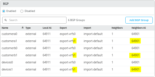
The following Junos OS CLI represents the entire configuration needed on the Series Firewall cluster for this example.
set groups node0 system host-name srx1_node0
set groups node1 system host-name srx2_node1
set apply-groups ""
set chassis aggregated-devices ethernet device-count 10
set chassis cluster control-link-recovery
set chassis cluster reth-count 5
set chassis cluster initial-hold 60
set chassis cluster redundancy-group 1 node 0 priority 200
set chassis cluster redundancy-group 1 node 1 priority 100
set chassis cluster redundancy-group 1 gratuitous-arp-count 4
# Interface monitoring turned OFF for vSRX
# set chassis cluster redundancy-group 1 interface-monitor ge-0/0/2 weight 255
# set chassis cluster redundancy-group 1 interface-monitor ge-0/0/3 weight 255
# set chassis cluster redundancy-group 1 interface-monitor ge-7/0/2 weight 255
# set chassis cluster redundancy-group 1 interface-monitor ge-7/0/3 weight 255
set interfaces fab0 fabric-options member-interfaces ge-0/0/0
set interfaces fab1 fabric-options member-interfaces ge-7/0/0
#
# rebuild trust zone to clear old interfaces bound
delete security zones security-zone trust
set security zones security-zone trust tcp-rst
set security zones security-zone trust host-inbound-traffic system-services all
set security zones security-zone trust host-inbound-traffic protocols all
#
delete interfaces ge-0/0/2
set interfaces ge-0/0/2 flexible-vlan-tagging
set interfaces ge-0/0/2 mtu 9018
set interfaces ge-0/0/2 unit 1091 description vlan1091
set interfaces ge-0/0/2 unit 1091 vlan-id 1091
set interfaces ge-0/0/2 unit 1091 family inet address 10.255.224.0/31
set security zones security-zone trust interfaces ge-0/0/2.1091 host-inbound-traffic protocols bgp
set security zones security-zone trust interfaces ge-0/0/2.1091 host-inbound-traffic system-services ping
set interfaces ge-0/0/2 unit 1081 description vlan1081
set interfaces ge-0/0/2 unit 1081 vlan-id 1081
set interfaces ge-0/0/2 unit 1081 family inet address 10.255.224.2/31
set security zones security-zone trust interfaces ge-0/0/2.1081 host-inbound-traffic protocols bgp
set security zones security-zone trust interfaces ge-0/0/2.1081 host-inbound-traffic system-services ping
set interfaces ge-0/0/2 unit 1031 description vlan1031
set interfaces ge-0/0/2 unit 1031 vlan-id 1031
set interfaces ge-0/0/2 unit 1031 family inet address 10.255.224.4/31
set security zones security-zone trust interfaces ge-0/0/2.1031 host-inbound-traffic protocols bgp
set security zones security-zone trust interfaces ge-0/0/2.1031 host-inbound-traffic system-services ping
#
delete interfaces ge-0/0/3
set interfaces ge-0/0/3 flexible-vlan-tagging
set interfaces ge-0/0/3 mtu 9018
set interfaces ge-0/0/3 unit 1091 description vlan1091
set interfaces ge-0/0/3 unit 1091 vlan-id 1091
set interfaces ge-0/0/3 unit 1091 family inet address 10.255.226.0/31
set security zones security-zone trust interfaces ge-0/0/3.1091 host-inbound-traffic protocols bgp
set security zones security-zone trust interfaces ge-0/0/3.1091 host-inbound-traffic system-services ping
set interfaces ge-0/0/3 unit 1081 description vlan1081
set interfaces ge-0/0/3 unit 1081 vlan-id 1081
set interfaces ge-0/0/3 unit 1081 family inet address 10.255.226.2/31
set security zones security-zone trust interfaces ge-0/0/3.1081 host-inbound-traffic protocols bgp
set security zones security-zone trust interfaces ge-0/0/3.1081 host-inbound-traffic system-services ping
set interfaces ge-0/0/3 unit 1031 description vlan1031
set interfaces ge-0/0/3 unit 1031 vlan-id 1031
set interfaces ge-0/0/3 unit 1031 family inet address 10.255.226.4/31
set security zones security-zone trust interfaces ge-0/0/3.1031 host-inbound-traffic protocols bgp
set security zones security-zone trust interfaces ge-0/0/3.1031 host-inbound-traffic system-services ping
#
delete interfaces ge-7/0/2
set interfaces ge-7/0/2 flexible-vlan-tagging
set interfaces ge-7/0/2 mtu 9018
set interfaces ge-7/0/2 unit 1099 description vlan1099
set interfaces ge-7/0/2 unit 1099 vlan-id 1099
set interfaces ge-7/0/2 unit 1099 family inet address 10.255.225.0/31
set security zones security-zone trust interfaces ge-7/0/2.1099 host-inbound-traffic protocols bgp
set security zones security-zone trust interfaces ge-7/0/2.1099 host-inbound-traffic system-services ping
set interfaces ge-7/0/2 unit 1088 description vlan1088
set interfaces ge-7/0/2 unit 1088 vlan-id 1088
set interfaces ge-7/0/2 unit 1088 family inet address 10.255.225.2/31
set security zones security-zone trust interfaces ge-7/0/2.1088 host-inbound-traffic protocols bgp
set security zones security-zone trust interfaces ge-7/0/2.1088 host-inbound-traffic system-services ping
set interfaces ge-7/0/2 unit 1033 description vlan1033
set interfaces ge-7/0/2 unit 1033 vlan-id 1033
set interfaces ge-7/0/2 unit 1033 family inet address 10.255.225.4/31
set security zones security-zone trust interfaces ge-7/0/2.1033 host-inbound-traffic protocols bgp
set security zones security-zone trust interfaces ge-7/0/2.1033 host-inbound-traffic system-services ping
#
delete interfaces ge-7/0/3
set interfaces ge-7/0/3 flexible-vlan-tagging
set interfaces ge-7/0/3 mtu 9018
set interfaces ge-7/0/3 unit 1099 description vlan1099
set interfaces ge-7/0/3 unit 1099 vlan-id 1099
set interfaces ge-7/0/3 unit 1099 family inet address 10.255.227.0/31
set security zones security-zone trust interfaces ge-7/0/3.1099 host-inbound-traffic protocols bgp
set security zones security-zone trust interfaces ge-7/0/3.1099 host-inbound-traffic system-services ping
set interfaces ge-7/0/3 unit 1088 description vlan1088
set interfaces ge-7/0/3 unit 1088 vlan-id 1088
set interfaces ge-7/0/3 unit 1088 family inet address 10.255.227.2/31
set security zones security-zone trust interfaces ge-7/0/3.1088 host-inbound-traffic protocols bgp
set security zones security-zone trust interfaces ge-7/0/3.1088 host-inbound-traffic system-services ping
set interfaces ge-7/0/3 unit 1033 description vlan1033
set interfaces ge-7/0/3 unit 1033 vlan-id 1033
set interfaces ge-7/0/3 unit 1033 family inet address 10.255.227.4/31
set security zones security-zone trust interfaces ge-7/0/3.1033 host-inbound-traffic protocols bgp
set security zones security-zone trust interfaces ge-7/0/3.1033 host-inbound-traffic system-services ping
#
# needed in and export policy
delete policy-options
set policy-options policy-statement fabric term 1 from protocol bgp
set policy-options policy-statement fabric term 1 from route-filter 0.0.0.0/0 orlonger
set policy-options policy-statement fabric term 1 then accept
set policy-options policy-statement fabric term 2 then reject
set policy-options policy-statement internet0 term 1 from protocol static
set policy-options policy-statement internet0 term 1 from route-filter 0.0.0.0/0 exact
set policy-options policy-statement internet0 term 1 then accept
set policy-options policy-statement internet0 term 2 then reject
set policy-options policy-statement internet1 term 1 from protocol static
set policy-options policy-statement internet1 term 1 from route-filter 0.0.0.0/0 exact
set policy-options policy-statement internet1 term 1 then as-path-prepend "64999 64999"
set policy-options policy-statement internet1 term 1 then accept
set policy-options policy-statement internet1 term 2 then reject
#
delete routing-instances public-int
set routing-instances public-int instance-type virtual-router
set routing-instances public-int interface ge-0/0/2.1091
set routing-instances public-int interface ge-0/0/2.1081
set routing-instances public-int interface ge-0/0/2.1031
set routing-instances public-int interface ge-0/0/3.1091
set routing-instances public-int interface ge-0/0/3.1081
set routing-instances public-int interface ge-0/0/3.1031
set routing-instances public-int interface ge-7/0/2.1099
set routing-instances public-int interface ge-7/0/2.1088
set routing-instances public-int interface ge-7/0/2.1033
set routing-instances public-int interface ge-7/0/3.1099
set routing-instances public-int interface ge-7/0/3.1088
set routing-instances public-int interface ge-7/0/3.1033
#
delete routing-instances public-int protocols bgp group customera
delete routing-instances public-int protocols bgp group customera0
set routing-instances public-int protocols bgp group customera0 type external
set routing-instances public-int protocols bgp group customera0 family inet unicast
set routing-instances public-int protocols bgp group customera0 multipath multiple-as
set routing-instances public-int protocols bgp group customera0 local-as 64901
set routing-instances public-int protocols bgp group customera0 hold-time 90
set routing-instances public-int protocols bgp group customera0 import fabric
set routing-instances public-int protocols bgp group customera0 export internet0
set routing-instances public-int protocols bgp group customera0 bfd-liveness-detection minimum-interval 1000
set routing-instances public-int protocols bgp group customera0 bfd-liveness-detection multiplier 3
set routing-instances public-int protocols bgp group customera0 bfd-liveness-detection session-mode automatic
set routing-instances public-int protocols bgp group customera0 neighbor 10.255.224.1 peer-as 64911
set routing-instances public-int protocols bgp group customera0 neighbor 10.255.226.1 peer-as 64911
#
delete routing-instances public-int protocols bgp group customera1
set routing-instances public-int protocols bgp group customera1 type external
set routing-instances public-int protocols bgp group customera1 family inet unicast
set routing-instances public-int protocols bgp group customera1 multipath multiple-as
set routing-instances public-int protocols bgp group customera1 local-as 64901
set routing-instances public-int protocols bgp group customera1 hold-time 90
set routing-instances public-int protocols bgp group customera1 import fabric
set routing-instances public-int protocols bgp group customera1 export internet1
set routing-instances public-int protocols bgp group customera1 bfd-liveness-detection minimum-interval 1000
set routing-instances public-int protocols bgp group customera1 bfd-liveness-detection multiplier 3
set routing-instances public-int protocols bgp group customera1 bfd-liveness-detection session-mode automatic
set routing-instances public-int protocols bgp group customera1 neighbor 10.255.225.1 peer-as 64911
set routing-instances public-int protocols bgp group customera1 neighbor 10.255.227.1 peer-as 64911
#
delete routing-instances public-int protocols bgp group customerb
delete routing-instances public-int protocols bgp group customerb0
set routing-instances public-int protocols bgp group customerb0 type external
set routing-instances public-int protocols bgp group customerb0 family inet unicast
set routing-instances public-int protocols bgp group customerb0 multipath multiple-as
set routing-instances public-int protocols bgp group customerb0 local-as 64901
set routing-instances public-int protocols bgp group customerb0 hold-time 90
set routing-instances public-int protocols bgp group customerb0 import fabric
set routing-instances public-int protocols bgp group customerb0 export internet0
set routing-instances public-int protocols bgp group customerb0 bfd-liveness-detection minimum-interval 1000
set routing-instances public-int protocols bgp group customerb0 bfd-liveness-detection multiplier 3
set routing-instances public-int protocols bgp group customerb0 bfd-liveness-detection session-mode automatic
set routing-instances public-int protocols bgp group customerb0 neighbor 10.255.224.3 peer-as 64911
set routing-instances public-int protocols bgp group customerb0 neighbor 10.255.226.3 peer-as 64911
#
delete routing-instances public-int protocols bgp group customerb1
set routing-instances public-int protocols bgp group customerb1 type external
set routing-instances public-int protocols bgp group customerb1 family inet unicast
set routing-instances public-int protocols bgp group customerb1 multipath multiple-as
set routing-instances public-int protocols bgp group customerb1 local-as 64901
set routing-instances public-int protocols bgp group customerb1 hold-time 90
set routing-instances public-int protocols bgp group customerb1 import fabric
set routing-instances public-int protocols bgp group customerb1 export internet1
set routing-instances public-int protocols bgp group customerb1 bfd-liveness-detection minimum-interval 1000
set routing-instances public-int protocols bgp group customerb1 bfd-liveness-detection multiplier 3
set routing-instances public-int protocols bgp group customerb1 bfd-liveness-detection session-mode automatic
set routing-instances public-int protocols bgp group customerb1 neighbor 10.255.225.3 peer-as 64911
set routing-instances public-int protocols bgp group customerb1 neighbor 10.255.227.3 peer-as 64911
#
delete routing-instances public-int protocols bgp group devices
delete routing-instances public-int protocols bgp group devices0
set routing-instances public-int protocols bgp group devices0 type external
set routing-instances public-int protocols bgp group devices0 family inet unicast
set routing-instances public-int protocols bgp group devices0 multipath multiple-as
set routing-instances public-int protocols bgp group devices0 local-as 64901
set routing-instances public-int protocols bgp group devices0 hold-time 90
set routing-instances public-int protocols bgp group devices0 import fabric
set routing-instances public-int protocols bgp group devices0 export internet0
set routing-instances public-int protocols bgp group devices0 bfd-liveness-detection minimum-interval 1000
set routing-instances public-int protocols bgp group devices0 bfd-liveness-detection multiplier 3
set routing-instances public-int protocols bgp group devices0 bfd-liveness-detection session-mode automatic
set routing-instances public-int protocols bgp group devices0 neighbor 10.255.224.5 peer-as 64911
set routing-instances public-int protocols bgp group devices0 neighbor 10.255.226.5 peer-as 64911
#
delete routing-instances public-int protocols bgp group devices1
set routing-instances public-int protocols bgp group devices1 type external
set routing-instances public-int protocols bgp group devices1 family inet unicast
set routing-instances public-int protocols bgp group devices1 multipath multiple-as
set routing-instances public-int protocols bgp group devices1 local-as 64901
set routing-instances public-int protocols bgp group devices1 hold-time 90
set routing-instances public-int protocols bgp group devices1 import fabric
set routing-instances public-int protocols bgp group devices1 export internet1
set routing-instances public-int protocols bgp group devices1 bfd-liveness-detection minimum-interval 1000
set routing-instances public-int protocols bgp group devices1 bfd-liveness-detection multiplier 3
set routing-instances public-int protocols bgp group devices1 bfd-liveness-detection session-mode automatic
set routing-instances public-int protocols bgp group devices1 neighbor 10.255.225.5 peer-as 64911
set routing-instances public-int protocols bgp group devices1 neighbor 10.255.227.5 peer-as 64911