Appendix: Layer 2 Exit with Transport VLAN
When creating any VLAN or VRF with campus fabric remember the following best practices:1. Create all VLANs in a switch template and then import them in the campus fabric configuration dialogue. Creating the VLANs anywhere else in the Juniper Mist portal ultimately leads to inconsistency which makes it hard to resolve issues.2. With the exception of the service block functions, do not create VRFs outside of the campus fabric configuration dialogue.3. The transport VLAN method requires you to create VRFs manually on the service block function and add the transport VLAN and routes locally to the VRFs. Do not create the VRFs or routes in the campus fabric configuration dialogue.4. We recommend that you create port profiles within switch templates so that any changes are in sync on all switches in the fabric.
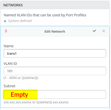
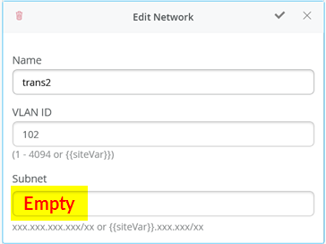
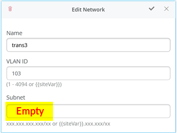
When defining the transport VLANs in the switch template, do not set the subnet information. You configure this information later as an Additional IP Subnet on each service block function. See Figure 1, Figure 2, and Figure 3.
The following CLI configuration shows the exported version of the switch template used in the transport VLAN fabric. This allows you to review our setup when importing. As you can see, there is a minimum of two VLANs per VRF plus an additional transport VLAN per VRF.
-
{
  "additional_config_cmds": [],
  "networks": {
    "vlan1099": {
      "vlan_id": 1099,
      "subnet": "10.99.99.0/24"
    },
    "vlan1088": {
      "vlan_id": 1088,
      "subnet": "10.88.88.0/24"
    },
    "vlan1033": {
      "vlan_id": 1033,
      "subnet": "10.33.33.0/24"
    },
    "vlan1091": {
      "vlan_id": 1091,
      "subnet": "10.99.91.0/24"
    },
    "vlan1081": {
      "vlan_id": 1081,
      "subnet": "10.88.81.0/24"
    },
    "vlan1031": {
      "vlan_id": 1031,
      "subnet": "10.33.31.0/24"
    },
    "trans1": {
      "vlan_id": "101",
      "subnet": ""
    },
    "trans2": {
      "vlan_id": "102",
      "subnet": ""
    },
    "trans3": {
      "vlan_id": "103",
      "subnet": ""
    }
  },
  "port_usages": {
    "vlan1099": {
      "mode": "access",
      "disabled": false,
      "port_network": "vlan1099",
      "voip_network": null,
      "stp_edge": false,
      "mac_auth_protocol": null,
      "all_networks": false,
      "networks": null,
      "port_auth": null,
      "enable_mac_auth": null,
      "mac_auth_only": null,
      "guest_network": null,
      "bypass_auth_when_server_down": null,
      "speed": "auto",
      "duplex": "auto",
      "mac_limit": 0,
      "persist_mac": false,
      "poe_disabled": false,
      "enable_qos": false,
      "storm_control": {},
      "mtu": null,
      "description": "",
      "disable_autoneg": false
    },
    "vlan1088": {
      "mode": "access",
      "disabled": false,
      "port_network": "vlan1088",
      "voip_network": null,
      "stp_edge": false,
      "mac_auth_protocol": null,
      "all_networks": false,
      "networks": null,
      "port_auth": null,
      "enable_mac_auth": null,
      "mac_auth_only": null,
      "guest_network": null,
      "bypass_auth_when_server_down": null,
      "speed": "auto",
      "duplex": "auto",
      "mac_limit": 0,
      "persist_mac": false,
      "poe_disabled": false,
      "enable_qos": false,
      "storm_control": {},
      "mtu": null,
      "description": "",
      "disable_autoneg": false
    },
    "dynamic": {
      "mode": "dynamic",
      "rules": []
    }
  },
  "switch_matching": {
    "enable": true,
    "rules": []
  },
  "switch_mgmt": {
    "config_revert_timer": 10,
    "root_password": "<password>",
    "protect_re": {
      "enabled": false
    },
    "tacacs": {
      "enabled": false
    }
  },
  "mist_nac": {
    "enabled": true,
    "network": null
  },
  "radius_config": {
    "auth_servers": [],
    "acct_servers": [],
    "auth_servers_timeout": 5,
    "auth_servers_retries": 3,
    "fast_dot1x_timers": false,
    "acct_interim_interval": 0,
    "auth_server_selection": "ordered",
    "coa_enabled": false,
    "coa_port": ""
  },
  "vrf_config": {
    "enabled": false
  },
  "remote_syslog": {
    "enabled": false
  },
  "snmp_config": {
    "enabled": false
  },
  "dhcp_snooping": {
    "enabled": false
  },
  "dns_servers": [],
  "dns_suffix": [],
  "ntp_servers": [],
  "acl_policies": [],
  "port_mirroring": {},
  "name": "campus-fabric"
}
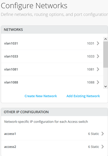
Within the Campus Fabric Configuration dialogue, there is a section called Configure Networks. This is where you import your six access VLANs from the switch template. When finished, the configuration should be as shown in Figure 4 and the result in our case will look as shown below. Since the three transport VLANs are not part of the access layer, they are not defined in the service block function.
Next, you create 3 VRFs and attach two of the access networks to each VRF as shown in Figure 5.
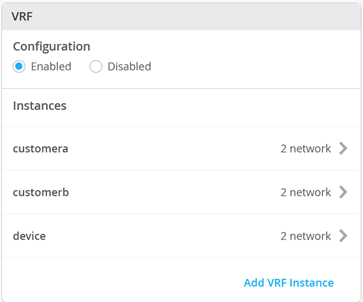
Next, go to each VRF and confirm that you only have access networks defined with no default route. You will define the transport VLANs and default routes later in the service block function. See Figure 6, Figure 7, and Figure 8.
Core1 and Core2 Switch Configuration
In the transport VLAN attach example, the service block function is virtual and co-located on the core switch. Therefore, you must configure the two core switches. The following pseudocode represents the configuration you must apply to the core1 and core2 switches:
-
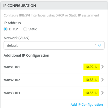
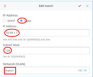
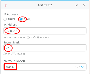
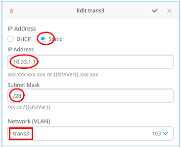
# configure the additional IP subnet 10.99.1.1/28 to network/VLAN:trans1
# configure the additional IP subnet 10.88.1.1/28 to network/VLAN:trans2
# configure the additional IP subnet 10.33.1.1/28 to network/VLAN:trans3
#
# Create a new local Port Profile called 'l2fabricexit' and configure:
# Mode='Trunk'
# Port Network (Untagged/Native VLAN)='None'
# Add the following 3 Networks as Trunk Networks:
# Network=trans1
# Network=trans2
# Network=trans3
# MTU='9018'
#
# Create a new Port configuration where:
# Port IDs=ge-0/0/3
# Interface=L2 Interface
# Configuration Profile=l2fabricexit
# Port Aggregation=Enable/Checked
# AE Index=11
# ESI-LAG=Enable/Checked
#
# Create a new Port configuration where:
# Port IDs=ge-0/0/4
# Interface=L2 Interface
# Configuration Profile=l2fabricexit
# Port Aggregation=Enable/Checked
# AE Index=12
# ESI-LAG=Enable/Checked
#
# In VRF Configuration
# Override Site/Template Settings=Checked
# In Instance customera
# Override Template Defined VRF Instance=Checked
# Add the Network trans1 to the existing list of networks
# Add the Extra Route 0.0.0.0/0 with via: 10.99.1.14
#
# In Instance customerb
# Override Template Defined VRF Instance=Checked
# Add the Network trans2 to the existing list of networks
# Add the Extra Route 0.0.0.0/0 with via: 10.88.1.14
#
# In Instance device
# Override Template Defined VRF Instance=Checked
# Add the Network trans3 to the existing list of networks
# Add the Extra Route 0.0.0.0/0 with via: 10.33.1.14
The following four images display the Juniper Mist portal configuration that results from the previous pseudocode starting with the additional IP configuration required to assign the local IP addresses to each transport VLAN.
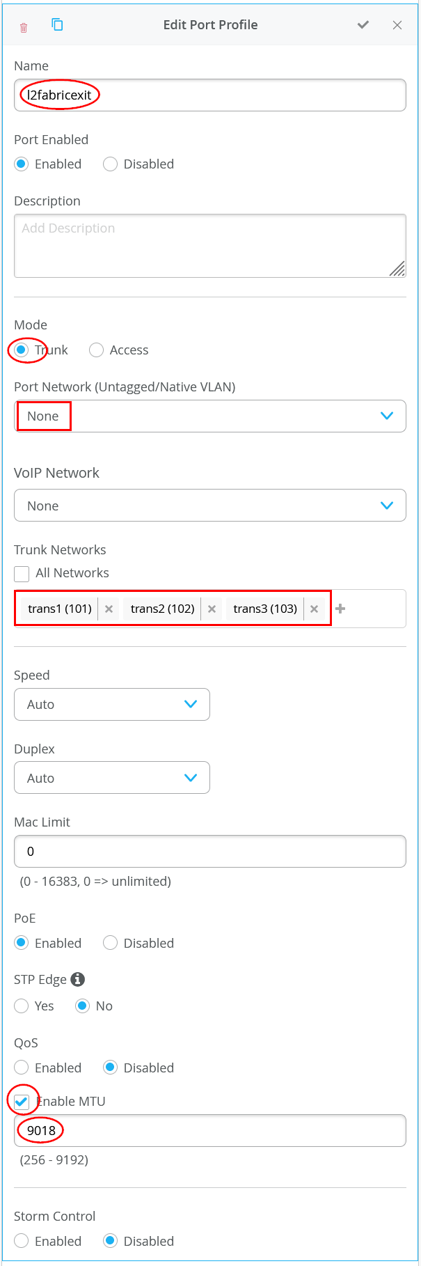
Next, you define the Port Profile used for the uplinks. It is critical that you only include the transport VLAN in the Trunk Networks definition since only those VLANs are used and visible to the WAN router.
Next, you assign the port profiles to each uplink port.
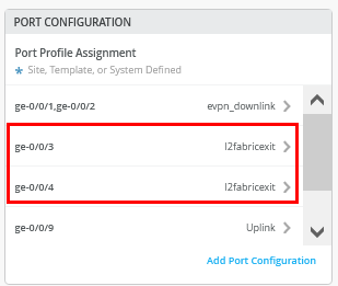
Figure 15 shows the configuration of the first uplink to the first WAN router.
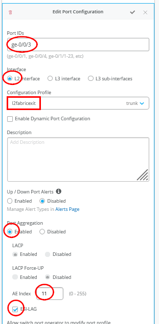
Figure 16 shows the configuration of the second uplink to the first WAN router.
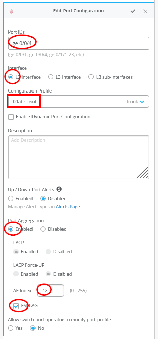
You must ensure that the AE Indexes on each service block function are in sync with each other towards the same WAN router and that you define them each as ESI-LAG. You must also ensure that you don’t reuse an AE Index that is already defined elsewhere in the fabric service block.
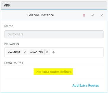
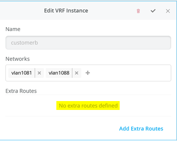
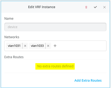
Next, you create and modify local VRFs. Remember, this is an exception made only for the transport VLAN exit method. Usually, the fabric creates the VRFs automatically. In this case, we must enable the Override Site/Template Settings checkbox in the VRF configuration. Figure 17 shows the required configuration in the Juniper Mist portal.
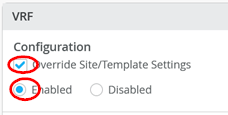
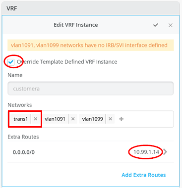
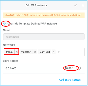
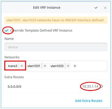
Next, you must perform the following three configurations in each of your three VRF instances:
- Enable the Override Template Defined VRF Instance checkbox.
- Add your transport VLAN to the pre-populated list of access VLANs.
- Add a default route where the gateway IP address is the VRRP VIP address of your WAN router.
Figure 18, Figure 19, and Figure 20 show the override configurations for each of the three VRFs.
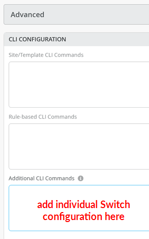
Now, you must configure additional CLI to modify the transport VLANs to use VGA configuration to help avoid excess hair-pin routing of traffic within the fabric. In the switch configuration for each of your service block function switches, locate the CLI Configuration section in the Juniper Mist portal. You must paste the required configuration into the field indicated in the figure below:
The example CLI configuration for your core1 switch, is shown in the following code block. We have configured the static IP address as the virtual gateway IP address + 1 (10.99.1.2).
-
# when service block function is a EX92xx change to VGA with the below
delete groups top routing-instances evpn_vs protocols evpn default-gateway do-not-advertise
set groups top routing-instances evpn_vs protocols evpn default-gateway no-gateway-community
#
# on non-EX92xx switches change to VGA with the below
# delete groups top protocols evpn default-gateway do-not-advertise
# set groups top protocols evpn default-gateway no-gateway-community
#
# modify our transport VLANs to VGA
delete interfaces irb unit 101 family inet address 10.99.1.1/28
set interfaces irb unit 101 family inet address 10.99.1.2/28 virtual-gateway-address 10.99.1.1
set interfaces irb unit 101 virtual-gateway-accept-data
set interfaces irb unit 101 virtual-gateway-v4-mac 00:00:5e:e4:05:01
#
delete interfaces irb unit 102 family inet address 10.88.1.1/28
set interfaces irb unit 102 family inet address 10.88.1.2/28 virtual-gateway-address 10.88.1.1
set interfaces irb unit 102 virtual-gateway-accept-data
set interfaces irb unit 102 virtual-gateway-v4-mac 00:00:5e:e4:05:02
#
delete interfaces irb unit 103 family inet address 10.33.1.1/28
set interfaces irb unit 103 family inet address 10.33.1.2/28 virtual-gateway-address 10.33.1.1
set interfaces irb unit 103 virtual-gateway-accept-data
set interfaces irb unit 103 virtual-gateway-v4-mac 00:00:5e:e4:05:03
For your core2 switch, only the static IP addresses of the transport VLAN are changed to be the virtual gateway IP address + 2 (10.88.1.3).
-
# when service block function is a EX92xx change to VGA with the below
delete groups top routing-instances evpn_vs protocols evpn default-gateway do-not-advertise
set groups top routing-instances evpn_vs protocols evpn default-gateway no-gateway-community
#
# on all non-EX92xx switches change to VGA with the below
# delete groups top protocols evpn default-gateway do-not-advertise
# set groups top protocols evpn default-gateway no-gateway-community
#
# modify our transport VLANs to VGA
delete interfaces irb unit 101 family inet address 10.99.1.1/28
set interfaces irb unit 101 family inet address 10.99.1.3/28 virtual-gateway-address 10.99.1.1
set interfaces irb unit 101 virtual-gateway-accept-data
set interfaces irb unit 101 virtual-gateway-v4-mac 00:00:5e:e4:05:01
#
delete interfaces irb unit 102 family inet address 10.88.1.1/28
set interfaces irb unit 102 family inet address 10.88.1.3/28 virtual-gateway-address 10.88.1.1
set interfaces irb unit 102 virtual-gateway-accept-data
set interfaces irb unit 102 virtual-gateway-v4-mac 00:00:5e:e4:05:02
#
#
delete interfaces irb unit 103 family inet address 10.33.1.1/28
set interfaces irb unit 103 family inet address 10.33.1.3/28 virtual-gateway-address 10.33.1.1
set interfaces irb unit 103 virtual-gateway-accept-data
set interfaces irb unit 103 virtual-gateway-v4-mac 00:00:5e:e4:05:03
# delete groups top protocols evpn default-gateway
do-not-advertise# set groups top protocols evpn default-gateway
no-gateway-community
Juniper MX as WAN Router
The following CLI snippet example contains the configuration of the interfaces, the VRRP gateway redundancy, and the static routes for the first WAN router. You may need to add default routes and interfaces to complete the configuration.
-
set system host-name wanrouter1
#
set chassis aggregated-devices ethernet device-count 10
#
delete interfaces ae0
delete policy-options policy-statement fabric
delete policy-options policy-statement internet
delete routing-instances public-int
#
set protocols lldp port-id-subtype interface-name
set protocols lldp interface all
set protocols lldp-med interface all
#
delete interfaces ge-0/0/1
set interfaces ge-0/0/1 gigether-options 802.3ad ae11
delete interfaces ge-0/0/2
set interfaces ge-0/0/2 gigether-options 802.3ad ae11
delete interfaces ae11
set interfaces ae11 mtu 9018
set interfaces ae11 aggregated-ether-options lacp active
set interfaces ae11 aggregated-ether-options lacp admin-key 11
set interfaces ae11 unit 0 family bridge interface-mode trunk
set interfaces ae11 unit 0 family bridge vlan-id-list 101
set interfaces ae11 unit 0 family bridge vlan-id-list 102
set interfaces ae11 unit 0 family bridge vlan-id-list 103
#
set bridge-domains trans1 vlan-id 101
set bridge-domains trans1 routing-interface irb.101
set bridge-domains trans2 vlan-id 102
set bridge-domains trans2 routing-interface irb.102
set bridge-domains trans3 vlan-id 103
set bridge-domains trans3 routing-interface irb.103
#
set interfaces irb unit 101 family inet address 10.99.1.13/28 vrrp-group 1 virtual-address 10.99.1.14
set interfaces irb unit 101 family inet address 10.99.1.13/28 vrrp-group 1 priority 110
set interfaces irb unit 101 family inet address 10.99.1.13/28 vrrp-group 1 accept-data
#
set interfaces irb unit 102 family inet address 10.88.1.13/28 vrrp-group 2 virtual-address 10.88.1.14
set interfaces irb unit 102 family inet address 10.88.1.13/28 vrrp-group 2 priority 110
set interfaces irb unit 102 family inet address 10.88.1.13/28 vrrp-group 2 accept-data
#
set interfaces irb unit 103 family inet address 10.33.1.13/28 vrrp-group 3 virtual-address 10.33.1.14
set interfaces irb unit 103 family inet address 10.33.1.13/28 vrrp-group 3 priority 110
set interfaces irb unit 103 family inet address 10.33.1.13/28 vrrp-group 3 accept-data
#
set routing-options static route 10.99.91.0/24 next-hop 10.99.1.1
set routing-options static route 10.99.99.0/24 next-hop 10.99.1.1
set routing-options static route 172.16.193.0/24 next-hop 10.99.1.1
#
set routing-options static route 10.88.81.0/24 next-hop 10.88.1.1
set routing-options static route 10.88.88.0/24 next-hop 10.88.1.1
set routing-options static route 172.16.194.0/24 next-hop 10.88.1.1
#
set routing-options static route 10.33.31.0/24 next-hop 10.33.1.1
set routing-options static route 10.33.33.0/24 next-hop 10.33.1.1
set routing-options static route 172.16.195.0/24 next-hop 10.33.1.1
On the second WAN router, the notable configuration changes are the AE keys and indexes, and the static IP addresses.
-
set system host-name wanrouter2
#
set chassis aggregated-devices ethernet device-count 10
#
set protocols lldp port-id-subtype interface-name
set protocols lldp interface all
set protocols lldp-med interface all
#
delete interfaces ge-0/0/1
set interfaces ge-0/0/1 gigether-options 802.3ad ae12
delete interfaces ge-0/0/2
set interfaces ge-0/0/2 gigether-options 802.3ad ae12
#
delete interfaces ae12
set interfaces ae12 mtu 9018
set interfaces ae12 aggregated-ether-options lacp active
set interfaces ae12 aggregated-ether-options lacp admin-key 12
set interfaces ae12 unit 0 family bridge interface-mode trunk
set interfaces ae12 unit 0 family bridge vlan-id-list 101
set interfaces ae12 unit 0 family bridge vlan-id-list 102
set interfaces ae12 unit 0 family bridge vlan-id-list 103
#
set bridge-domains trans1 vlan-id 101
set bridge-domains trans1 routing-interface irb.101
set bridge-domains trans2 vlan-id 102
set bridge-domains trans2 routing-interface irb.102
set bridge-domains trans3 vlan-id 103
set bridge-domains trans3 routing-interface irb.103
#
set interfaces irb unit 101 family inet address 10.99.1.12/28 vrrp-group 1 virtual-address 10.99.1.14
set interfaces irb unit 101 family inet address 10.99.1.12/28 vrrp-group 1 accept-data
#
set interfaces irb unit 102 family inet address 10.88.1.12/28 vrrp-group 2 virtual-address 10.88.1.14
set interfaces irb unit 102 family inet address 10.88.1.12/28 vrrp-group 2 accept-data
#
set interfaces irb unit 103 family inet address 10.33.1.12/28 vrrp-group 3 virtual-address 10.33.1.14
set interfaces irb unit 103 family inet address 10.33.1.12/28 vrrp-group 3 accept-data
#
set routing-options static route 10.99.91.0/24 next-hop 10.99.1.1
set routing-options static route 10.99.99.0/24 next-hop 10.99.1.1
set routing-options static route 172.16.193.0/24 next-hop 10.99.1.1
#
set routing-options static route 10.88.81.0/24 next-hop 10.88.1.1
set routing-options static route 10.88.88.0/24 next-hop 10.88.1.1
set routing-options static route 172.16.194.0/24 next-hop 10.88.1.1
#
set routing-options static route 10.33.31.0/24 next-hop 10.33.1.1
set routing-options static route 10.33.33.0/24 next-hop 10.33.1.1
set routing-options static route 172.16.195.0/24 next-hop 10.33.1.1
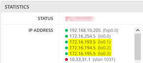
You may wonder about those static routes in the 172.16.19x.0 range. Remember that IP Clos is an anycast fabric. As such, you must have the static routes to prepare for when the DHCP relay will use IP addresses in the fabric overlay. See the figure below for an example:
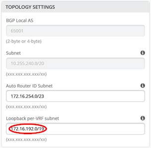
The overlay loopbacks IPs are assigned to each VRF on a switch as a /24 range. You can figure them out by looking at a fabric access switch as shown in the figure below. Hence, you must map them back like any other additional VLAN attached to the VRF to achieve the required reachability.
The following commands help to debug the connections on WAN router1.
-
root@wanrouter1> show lldp neighbors
Local Interface    Parent Interface    Chassis Id                               Port info          System Name
ge-0/0/0           -                   4c:96:14:95:09:80                        516                 internet
ge-0/0/1           ae11                2c:6b:f5:3a:42:c0                        ge-0/0/3            core1
ge-0/0/2           ae11                2c:6b:f5:7f:7d:c0                        ge-0/0/3            core2
.
root@wanrouter1> show lacp interfaces
Aggregated interface: ae11
    LACP state:           Role   Exp   Def  Dist  Col  Syn  Aggr  Timeout  Activity
      ge-0/0/1           Actor    No    No   Yes  Yes  Yes   Yes     Fast    Active
      ge-0/0/1         Partner    No    No   Yes  Yes  Yes   Yes     Fast    Active
      ge-0/0/2           Actor    No    No   Yes  Yes  Yes   Yes     Fast    Active
      ge-0/0/2         Partner    No    No   Yes  Yes  Yes   Yes     Fast    Active
    LACP protocol:        Receive State  Transmit State          Mux State
      ge-0/0/1                  Current   Fast periodic Collecting distributing
      ge-0/0/2                  Current   Fast periodic Collecting distributing
.
root@wanrouter1> show vrrp
Interface     State       Group   VR state VR Mode   Timer    Type   Address
irb.101       up              1   master   Active      A  0.350 lcl    10.99.1.13
                                                                vip    10.99.1.14
irb.102       up              2   master   Active      A  0.625 lcl    10.88.1.13
                                                                vip    10.88.1.14
irb.103       up              3   master   Active      A  0.830 lcl    10.33.1.13
                                                                vip    10.33.1.14
The following commands help you to debug connections on WAN router2.
-
root@wanrouter2> show lldp neighbors
Local Interface    Parent Interface    Chassis Id                               Port info          System Name
ge-0/0/0           -                   4c:96:14:95:09:80                        517                 internet
ge-0/0/1           ae12                2c:6b:f5:3a:42:c0                        ge-0/0/4            core1
ge-0/0/2           ae12                2c:6b:f5:7f:7d:c0                        ge-0/0/4            core2
.
root@wanrouter2> show lacp interfaces
Aggregated interface: ae12
    LACP state:           Role   Exp   Def  Dist  Col  Syn  Aggr  Timeout  Activity
      ge-0/0/1           Actor    No    No   Yes  Yes  Yes   Yes     Fast    Active
      ge-0/0/1         Partner    No    No   Yes  Yes  Yes   Yes     Fast    Active
      ge-0/0/2           Actor    No    No   Yes  Yes  Yes   Yes     Fast    Active
      ge-0/0/2         Partner    No    No   Yes  Yes  Yes   Yes     Fast    Active
    LACP protocol:        Receive State  Transmit State          Mux State
      ge-0/0/1                  Current   Fast periodic Collecting distributing
      ge-0/0/2                  Current   Fast periodic Collecting distributing
.
root@wanrouter2> show vrrp
Interface     State       Group   VR state VR Mode   Timer    Type   Address
irb.101       up              1   backup   Active      D  2.811 lcl    10.99.1.12
                                                                vip    10.99.1.14
                                                                mas    10.99.1.13
irb.102       up              2   backup   Active      D  3.303 lcl    10.88.1.12
                                                                vip    10.88.1.14
                                                                mas    10.88.1.13
irb.103       up              3   backup   Active      D  2.798 lcl    10.33.1.12
                                                                vip    10.33.1.14
                                                                mas    10.33.1.13