ON THIS PAGE
Technical overview
Campus Fabric IP Clos High-Level Architecture
The campus fabric, with an EVPN-VXLAN architecture, decouples the overlay network from the underlay network. This approach addresses the needs of the modern enterprise network by allowing network administrators to create logical L2 networks across one or more L3 networks. By configuring different routing instances, you can enforce the separation of virtual networks because each routing instance has its own separate routing and switching table.
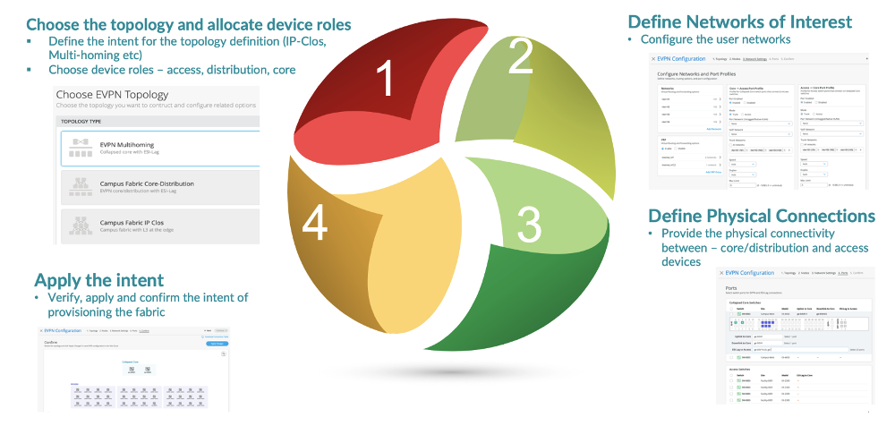
The Juniper Mist™ portal workflow makes it easy to create campus fabrics.
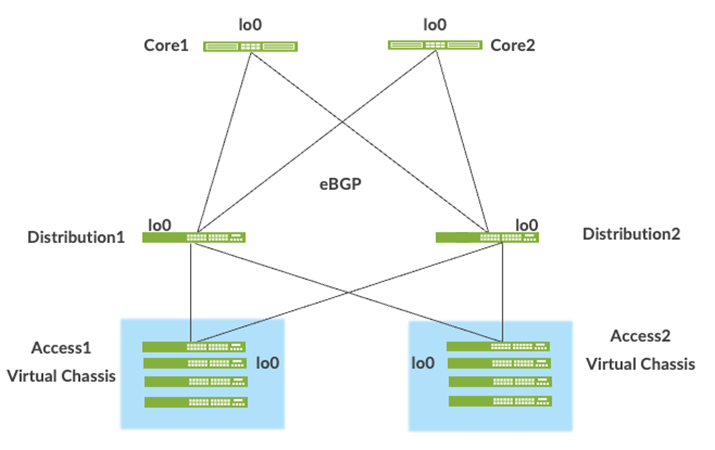
Underlay Network
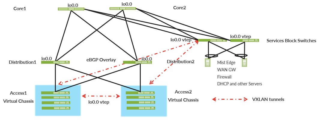
An EVPN-VXLAN fabric architecture makes the network infrastructure simple and consistent across campuses and data centers. All the core, distribution, and access devices must be connected using an L3 infrastructure. We recommend deploying a Clos-based IP fabric to ensure predictable performance and to enable a consistent, scalable architecture.
You can use any L3 routing protocol to exchange loopback addresses between the access, core, and distribution devices. BGP provides benefits such as better prefix filtering, traffic engineering, and route tagging. We are using eBGP as the underlay routing protocol in this example. Mist automatically provisions Private Autonomous System numbers and all BGP configurations for the underlay and overlay for only the campus fabric. There are options to provide additional BGP speakers to allow you to peer with external BGP peers.
Underlay BGP is used to learn loopback addresses from peers so that the overlay BGP can establish neighbors using the loopback address. The overlay is then used to exchange EVPN routes.
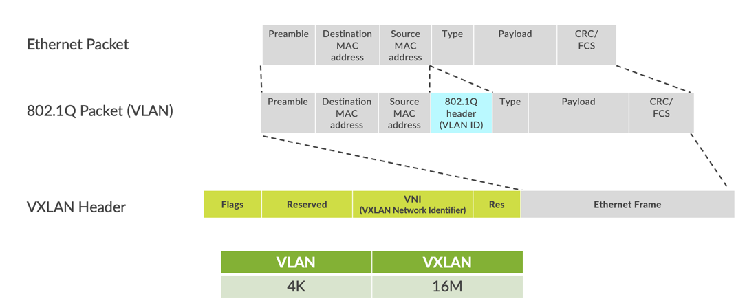
Network overlays enable connectivity and addressing independent of the physical network. Ethernet frames are wrapped in UDP/IP datagrams, which are encapsulated into IP for transport over the underlay. VXLAN enables virtual L2 subnets or VLANs to span underlying physical L3 network.
In a VXLAN overlay network, each L2 subnet or segment is uniquely identified by a Virtual Network Identifier (VNI). A VNI segments traffic the same way that a VLAN ID does. This mapping occurs on the access switches and border gateway, which can reside on the core or service block. As is the case with VLANs, endpoints within the same virtual network can communicate directly with each other.
Endpoints in different virtual networks require a device that supports inter-VXLAN routing, which is typically a router, or a high-end switch known as an L3 gateway. The entity that performs VXLAN encapsulation and decapsulation is called a VTEP. Each VTEP is known as the L2 gateway and is typically assigned with the device's loopback address. This is also where VXLAN (commonly known as VNI) to VLAN mapping takes place.
VXLAN can be deployed as a tunnelling protocol across an L3 IP campus fabric without a control plane protocol. However, the use of VXLAN tunnels alone does not change the flood and learn behavior of the Ethernet protocol.
The two primary methods for using VXLAN without a control plane protocol are static unicast VXLAN tunnels and VXLAN tunnels. These methods are signaled with a multicast underlay and do not solve the inherent flood and learn problem. These methods are also difficult to scale in large, multitenant environments. These methods are not in the scope of this JVD.
Understanding EVPN
EVPN is a BGP extension to distribute endpoint reachability information such as MAC and IP addresses to other BGP peers. This control plane technology uses Multiprotocol BGP (MP-BGP) for MAC and IP address endpoint distribution, where MAC addresses are treated as Type 2 EVPN routes. EVPN enables devices acting as VTEPs to exchange reachability information with each other about their endpoints.
Juniper supported EVPN Standards: https://www.juniper.net/documentation/us/en/software/junos/evpn-vxlan/topics/concept/evpn.html
What is EVPN-VXLAN: https://www.juniper.net/us/en/research-topics/what-is-evpn-vxlan.html
The benefits of using EVPNs include:
- MAC address mobility
- Multitenancy
- Load balancing across multiple links
- Fast convergence
- High availability
- Scale
- Standards-based interoperability
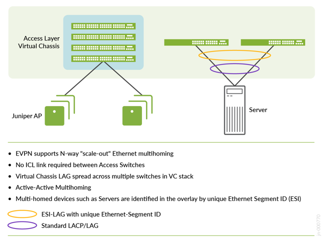
EVPN provides multipath forwarding and redundancy through an all-active model. The access layer can connect to two or more distribution devices and forward traffic using all the links. If an access link or distribution device fails, traffic flows from the access layer toward the distribution layer using the remaining active links. For traffic in the other direction, remote distribution devices update their forwarding tables to send traffic to the remaining active distribution devices connected to the multihomed Ethernet segment.
The technical capabilities of EVPN include:
- Minimal flooding—EVPN creates a control plane that shares end-host MAC addresses between VTEPs.
- Multihoming—EVPN supports multihoming for client devices. A control protocol like EVPN that enables synchronization of endpoint addresses between the access switches is needed to support multihoming because traffic traveling across the topology needs to be intelligently moved across multiple paths.
- Aliasing—EVPN leverages all-active multihoming when connecting devices to the access layer of a campus fabric. The connection of the multihomed access layer switches is called ESI-LAG, while the access layer devices connect to each access switch using standard LACP.
- Split horizon—Split horizon prevents the looping of BUM traffic in a network. With split horizon, a packet is never sent back over the same interface it was received on, which prevents loops.
Overlay Network (Data Plane)
VXLAN is the overlay data plane encapsulation protocol that tunnels Ethernet frames between network endpoints over the underlay network. A device that performs VXLAN encapsulation and decapsulation for the network is referred to as a VTEP. Before a VTEP sends a frame into a VXLAN tunnel, it wraps the original frame in a VXLAN header that includes a Virtual Network Identifier (VNI). The VNI maps the packet to the original VLAN at the ingress switch. After applying a VXLAN header, the frame is encapsulated into a UDP/IP datagram for transmission to the remote VTEP over the IP fabric, where the VXLAN header is removed and the VNI-to-VLAN translation happens at the egress switch.
VTEPs are software entities tied to the devices’ loopback address that source and terminate VXLAN tunnels. VXLAN tunnels in an IP Clos fabric are provisioned on the following:
- Access switches to extend services across the campus fabric IP Clos.
- Core switches, when acting as a border router, interconnect the campus fabric with the outside network.
- Service block devices that interconnect the campus fabric with the outside network.
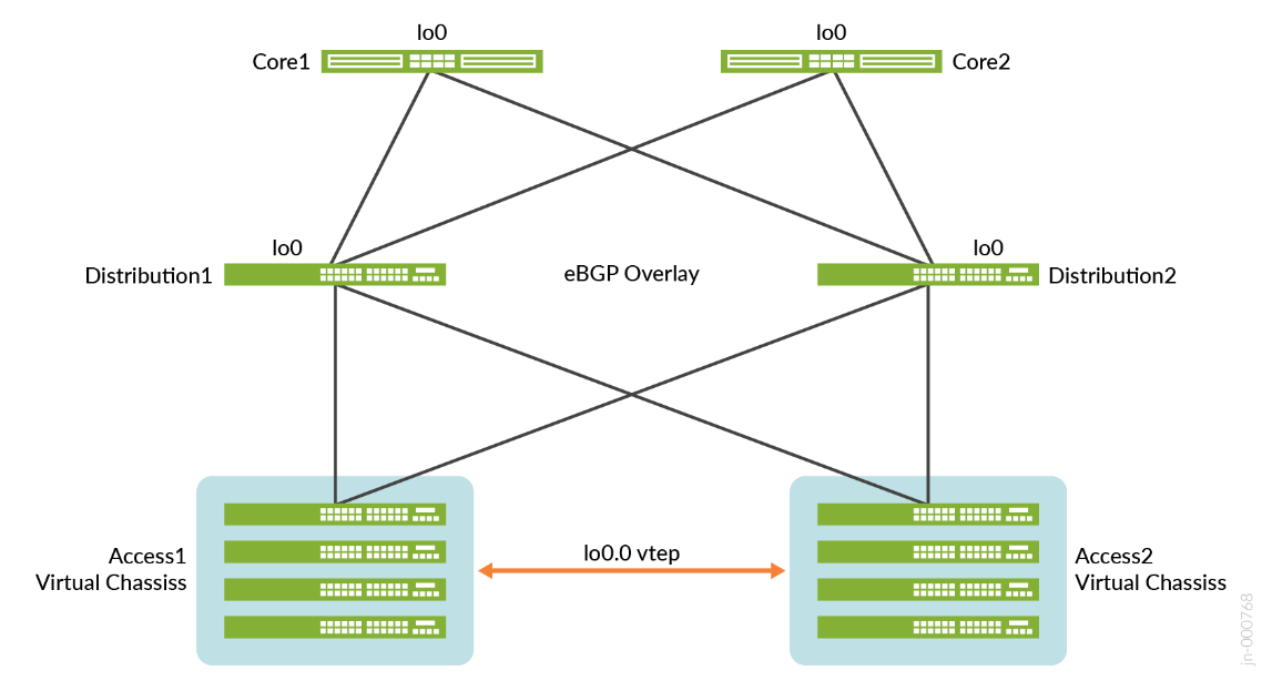
Overlay Network (Control Plane)
Multiprotocol Border Gateway Protocol (MP-BGP) with EVPN signaling acts as the overlay control plane protocol. Adjacent layer switches set up eBGP peers using their loopback addresses with next hops announced by the underlay BGP sessions. For example, core and distribution devices establish eBGP sessions between each other while the access and distribution devices establish eBGP sessions between each other. When there is an L2 forwarding table update on any switch participating in the campus fabric, it sends a BGP update message with the new MAC route to other devices in the fabric. Those devices then update their local EVPN database and routing tables.
Resiliency and Load Balancing
We support BFD as part of the BGP protocol implementation. This provides fast convergence in the event of a device or link failure without relying on the routing protocol’s timers. Juniper Mist configures BFD with minimum intervals of 1000ms in the underlay and overlay respectively. Load balancing, per packet by default, is supported across all links within the campus fabric using equal-cost multipath (ECMP) routing enabled at the forwarding plane.
Ethernet Segment Identifier (ESI)
When devices such as servers and access points are multihomed to two or more switches at the access layer in a campus fabric, an ESI-LAG is formed on the access layer devices. This ESI is a 10-octet integer that identifies the Ethernet segment amongst all access layer switches participating in the ESI. MP-BGP is the control plane protocol used to coordinate this information. An ESI-LAG enables link failover in the event of a bad link, supports active-active load balancing, and is automatically assigned by Juniper Mist.
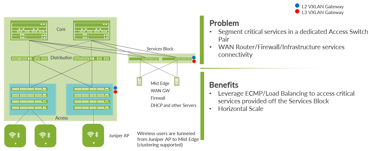
Service Block
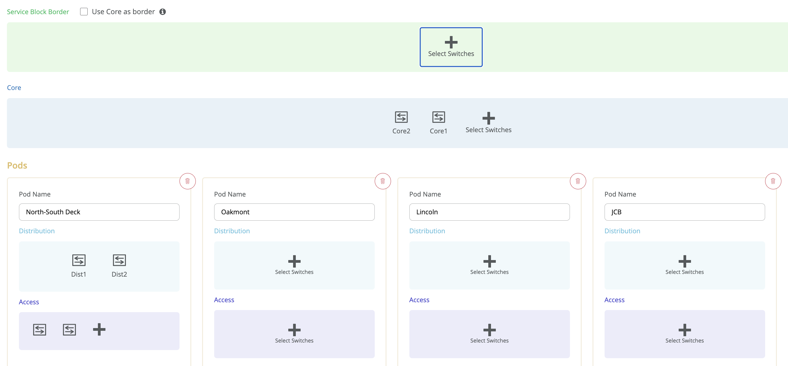
You need to position critical infrastructure services off of a dedicated pair of Juniper Networks switches. This can include WAN and firewall connectivity, RADIUS, and DHCP servers, for example. If you need to deploy a lean core, the dedicated service block mitigates the need for the core to support encapsulation and de-encapsulation of VXLAN tunnels, multiple routing instances, and additional L3 routing protocols. The service block border capability is supported directly off of the core layer or as a dedicated pair of switches.
Access Layer
The access layer provides network connectivity to end-user devices, such as personal computers, VoIP phones, printers, IoT devices, as well as connectivity to wireless access points. The EVPN-VXLAN network extends all the access layer switches.
.png)
In this example, each access switch or Virtual Chassis is multihomed to two or more distribution switches. Juniper’s Virtual Chassis reduces the number of ports required on distribution switches and optimizes the availability of fiber throughout the campus. The Virtual Chassis supports up to 10 member switches (depending on the switch model) and is managed as a single device. See https://www.juniper.net/documentation/us/en/software/junos/vcf-best-practices-guide/vcf-best-practices-guide.pdf.
With EVPN running as the control plane protocol, any access switch or Virtual Chassis device can enable active-active multihoming to the distribution layer. EVPN provides a standards-based multihoming solution that scales horizontally across any number of access layer switches.
Single or Multiple PoD Design
Juniper Mist campus fabric supports deployments with only one point of delivery (PoD) (formally called Site-Design) or multiple PoDs. The organizational deployment shown below, targets enterprises who need to align with a multi-PoD structure:
Juniper Access Points
In our network, we choose Juniper access points (APs) as our preferred AP devices. They are designed from the ground up to meet the stringent networking needs of the modern cloud and smart device era. Juniper Mist delivers unique capabilities for both wired and wireless LAN:
- Wired and Wireless Assurance—Juniper Mist is enabled with wired and wireless assurance. Once configured, Service-Level Expectations (SLE) for key wired and wireless performance metrics such as throughput, capacity, roaming, and uptime are monitored in the Juniper Mist platform. This JVD uses Juniper Mist Wired Assurance cloud services.
- Marvis® Virtual Network Assistant—An integrated AI engine that provides rapid wired and wireless troubleshooting, trending analysis, anomaly detection, and proactive problem remediation.
Juniper Mist Edge
For large campus networks, Juniper Mist™ Edge provides seamless roaming through on-premises tunnel termination of traffic to and from the Juniper APs. Juniper Mist Edge extends select microservices to the customer premises while using the Juniper Mist cloud and its distributed software architecture for scalable and resilient operations, management, troubleshooting, and analytics. Juniper Mist Edge is deployed as a standalone appliance with multiple variants for different-size deployments.
Evolving IT departments look for a cohesive approach for managing wired, wireless, and wan networks. This full-stack approach simplifies and automates operations, provides end-to-end troubleshooting, and ultimately evolves into the Self-Driving Network™. The integration of the Juniper Mist platform in this JVD addresses both full-stack deployments and automation.
Campus Fabric IP Clos Deployment Types
Juniper Mist’s Wired Assurance supports 3-stage and 5-stage IP Clos deployments depending on scale and PoD design.
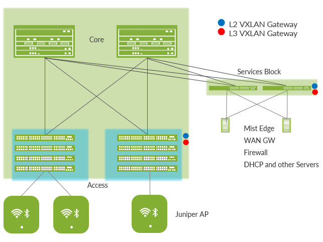
3-Stage IP Clos
The 3-stage IP Clos is targeted for deployments that do not require a distribution layer and have smaller-scale requirements.
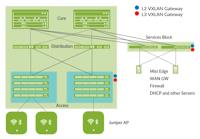
5-Stage IP Clos
The 3-stage IP Clos is the recommended deployment with access, distribution and core layer. It is also recommended when using multiple PoDs that then peer using the core switches (not shown in the below figure).
Supported Platforms for Campus Fabric IP Clos
Table 1 lists the supported platforms for campus fabric IP Clos deployments.
| Supported Platforms | |
|---|---|
| Campus Fabric IP Clos Deployment | Supported Platforms |
| Access layer |
EX4100 EX4300-MP EX4400 |
| Distribution layer |
EX4400-24X EX4650 QFX5120 QFX5130 QFX5700 EX92xx |
| Core layer |
EX4650 QFX5120 QFX5130 QFX5700 QFX10000 EX92xx |
| Service block |
EX4400-24X EX4650 QFX5120 QFX5130 QFX5700 EX92xx |
A hardware limitation on the Juniper Networks® EX4300-MP Switch does not allow it to be used for VXLAN-GBP. Consider the Juniper Networks® EX4100 or Juniper Networks® EX4400 Switches for such a feature.
Juniper Mist Wired Assurance
Juniper Mist Wired Assurance is a cloud service that brings automated operations and service levels to the campus fabric for switches, IoT devices, access points, servers, and printers. It is about simplifying every step of the way, starting from Day 0 for seamless onboarding and auto-provisioning through Day 2 and beyond for operations and management. Juniper Networks® EX Series Switches provide Junos streaming telemetry that enable the insights for switch health metrics and anomaly detection, as well as Mist AI™ capabilities.
Mist’s AI engine and virtual network assistant, Marvis, further simplifies troubleshooting while streamlining helpdesk operations by monitoring events and recommending actions. Marvis is one step towards the Self-Driving Network, turning insights into actions and transforming IT operations from reactive troubleshooting to proactive remediation.
Juniper Mist cloud services are 100% programmable using open APIs for full automation and/or integration with your operational support systems. For example, IT applications such as ticketing systems and IP management systems.
Juniper Mist delivers unique capabilities for the WAN, LAN, and wireless networks:
- A UI or API-driven configuration at scale.
- Service-level expectations (SLEs) for key performance metrics such as throughput, capacity, roaming, and uptime.
- Marvis—An integrated AI engine that provides rapid troubleshooting of full-stack network issues, trending analysis, anomaly detection, and proactive problem remediation.
- A single management system.
- License management.
- Premium analytics for long term trending and data storage.
To learn more about Juniper Mist Wired Assurance, see the following datasheet: https://www.juniper.net/content/dam/www/assets/datasheets/us/en/cloud-services/juniper-mist-wired-assurance-datasheet.pdf