APPENDIX: Mist Edge Integration into IP-Clos Fabric (Optional)
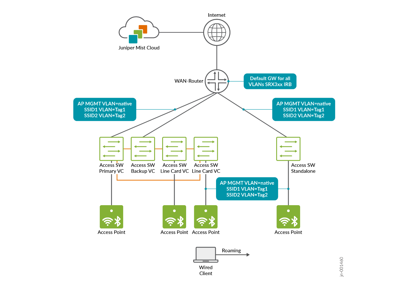
An enterprise Wi-Fi access point (AP) can be thought of as an L2 MAC bridge. One side communicates wirelessly with client devices, while the other side connects to the wired Ethernet network. Because of this, APs do not perform L3 gateway functions for a VLAN. Instead, it is expected that somewhere in the network—at the point where the AP’s Ethernet port connects—the L3 default gateway for the VLAN is provided. In most cases this means:
- In simple branch deployments, the Layer 3 gateway for a VLAN is typically located on the WAN router. Both switches and APs connect to this router, and in many cases the DHCP server function is also hosted on the WAN router.
- In campus fabric deployments, the Layer 3 gateway for a VLAN resides in the VRF of the fabric. The exact placement of the VRF depends on the campus fabric design, but in these environments, the fabric usually performs only a DHCP relay function rather than acting as the DHCP server itself.
Juniper Mist Wi-Fi supports two primary models for forwarding traffic from APs into the network:
- The first is a distributed model, in which wireless client traffic is broken out locally at the AP. In this approach, the AP broadcasts an SSID and associates clients with it, then maps their traffic to a tagged VLAN on the Ethernet side of the AP. In some cases, client traffic may also be switched directly to another device connected to the same AP and SSID, without leaving the AP.
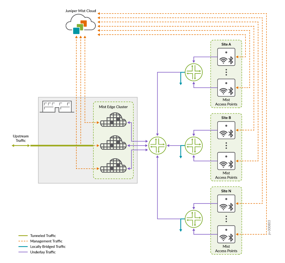
- The second option is a centralized, or tunneled, approach where wireless client traffic is broken out remotely at a central traffic Data Plane Concentrator known as Mist Edge. In this model, the access point establishes an overlay transport tunnel to the tunneling endpoint using the tunnelling head end's remote IP address. The tunnel can operate across any routed network or VLAN, providing flexibility in deployment. For the tunnel, Juniper Mist uses the L2TPv3 protocol, which can be further secured by enabling IPsec protection. Once the traffic reaches the tunnelling head end, it is broken out into the appropriate VLANs as configured, typically based on the SSID settings. This approach centralizes traffic handling and allows for consistent policy enforcement at a single point in the network.
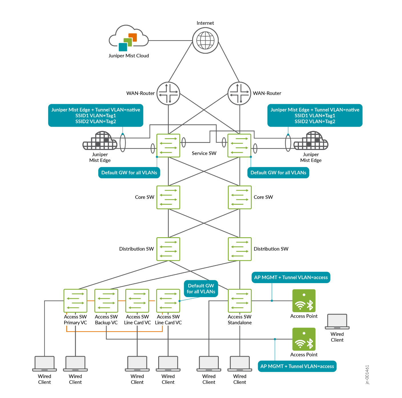
When the centralized approach is used with an EVPN fabric such as campus fabric IP Clos, we recommend the following setup:
- Configure an AP overlay network for campus fabric where:
- The AP gets a DHCP lease using DHCP relay on the fabric.
- After getting an IP address, the AP reaches out to the Juniper Mist cloud to get managed.
- After the tunnel configuration is applied, an unsecured L2TPv3 tunnel can be built to the Mist Edge device’s tunnel termination IP address in the same VLAN.
- Configure individual wireless client breakout overlay networks
(similar to regular wired networks) for campus fabric according to
your requirements and make sure that:
- The wireless clients mapped to these networks are getting DHCP leases using DHCP relay on the fabric.
- Attach your AP at the access switch and power them up.
- Only the AP overlay network needs to be configured as access port type.
- Attach at least two (for redundancy) Mist Edge devices at the
top of the EVPN fabric at the service block function which is
usually the integration point for other network services like the
WAN router, firewalls and servers.
- Each Mist Edge must have an interface to each service block function.
- On the fabric side towards each Mist Edge, configure a unique ESI-LAG.
- The Mist Edge interfaces (apart from the OOBM) are using a simple LAG towards the fabric.
- On both sides, the AP overlay network is configured as a native VLAN without tags.
- On both sides, the individual wireless client breakout overlay networks are configured as tagged VLANs.
This recommended configuration enables the EVPN fabric to gather wireless client traffic from the APs through the tunnels at the top of the fabric and then reinject it back into the network. This approach ensures seamless communication between wireless and wired clients, while also supporting traffic flows to the Internet outside of the EVPN fabric.
The choice of which approach to use should be determined during the design phase of an EVPN fabric. The centralized approach with Mist Edges in an EVPN fabric is recommended when the following conditions apply:
- More than 2.000 wireless clients are expected in the EVPN fabric.
- You have an expectation of “fast” roaming wireless clients through the APs of the network.
It is important to remember that the decision to roam is ultimately made by the wireless client itself. Unlike cellular networks, where the base station controls and can trigger roaming, Wi-Fi does not have this capability built into its standard functions. In Wi-Fi, the AP network can only attempt to encourage or guide the client to roam, but the final decision always rests with the client device. Because there are many different Wi-Fi network interface cards (NICs) on the market, each with its own firmware and internal configuration, predicting how a specific client will behave when roaming is extremely difficult. As a result, roaming behavior can vary significantly between devices.When using the centralized model with Juniper Mist Edge, it is considered best practice to use different VLANs for client access at the switch layer than those used for breakout at the Juniper Mist Edge service block at the top of the EVPN fabric. These VLANs may reside within the same VRF but separating them into distinct L2 domains is recommended. If both layers share the same L2 domain, all MAC addresses must be learned by both the access layer and the service block, which can affect scalability. Using separate L2 domains avoids this issue. Refer to the next section for more detailed guidance.
Design for High Scale of Wired and Wireless Clients with EVPN Fabrics
With the right design, using Juniper Mist Edge allows you to support a larger number of wired and wireless clients within a single fabric. To accomplish this, the VLANs used for wired clients at the access layer should be separated from the VLANs used for wireless clients, and the locations of their default gateways (VRFs) should reside on different layers of the fabric, handled by different fabric switches. This capability is planned as a future enhancement that will be applied automatically when creating a new campus fabric.
For now, contact your Juniper representative if you need these details in advance. Once the new feature is available, its announcement will be posted here for review. In the meantime, it is helpful to understand the required design changes ahead of time, so you are prepared when the enhancement becomes available.
The recommended VLAN structure for achieving independent, high-scale client designs is as follows:
- Plan for one or more VLANs used by APs to obtain DHCP leases, connect to the Juniper Mist cloud, and establish tunnels to the Juniper Mist Edge. These VLANs should exist only at the access switch and are typically configured as native VLANs on the switch ports.
- Plan for a small VLAN that provides the tunnel termination IP address for the Juniper Mist Edges. APs send remotely-broken-out wireless client traffic to this address. Deploy this VLAN only at the service block where the Juniper Mist Edge is connected, usually as the native VLAN on the Juniper Mist Edge’s LAG trunk. Make sure the AP tunnel VLANs and the Mist Edge tunnel VLAN are in the same VRF; otherwise, traffic will be forced through a WAN router due to VRF isolation. This separation helps ensure that even with many APs, the Juniper Mist Edge only needs to track the default gateway’s local IP address instead of maintaining ARP entries for every AP.
- Plan for one or more VLANs that receive Wi-Fi client traffic forwarded by the AP and handed off at the Juniper Mist Edge. These VLANs are typically trunked and carried across the Juniper Mist Edge’s LAG interfaces into the EVPN fabric via ESI-LAG. They should only be configured at the service block to maintain the intended scale separation.
- Plan for one or more VLANs dedicated to wired client traffic. These VLANs should be defined only at the EVPN fabric access layer. If you expect communication between wired and wireless clients, consider placing their VLANs in the same VRF so that traffic can be exchanged within the EVPN fabric.
- If additional infrastructure services (such as servers) are connected at the service block, ensure they use their own VLANs that exist only at the service block where the wireless client VLANs reside. Using the same VRF is again recommended when possible.
Further details on scaling Juniper Mist Edges are covered in the following sections.
Wireless Client Roaming in EVPN Fabrics
The concepts behind MAC address mobility in EVPN networks are explained in the following link.
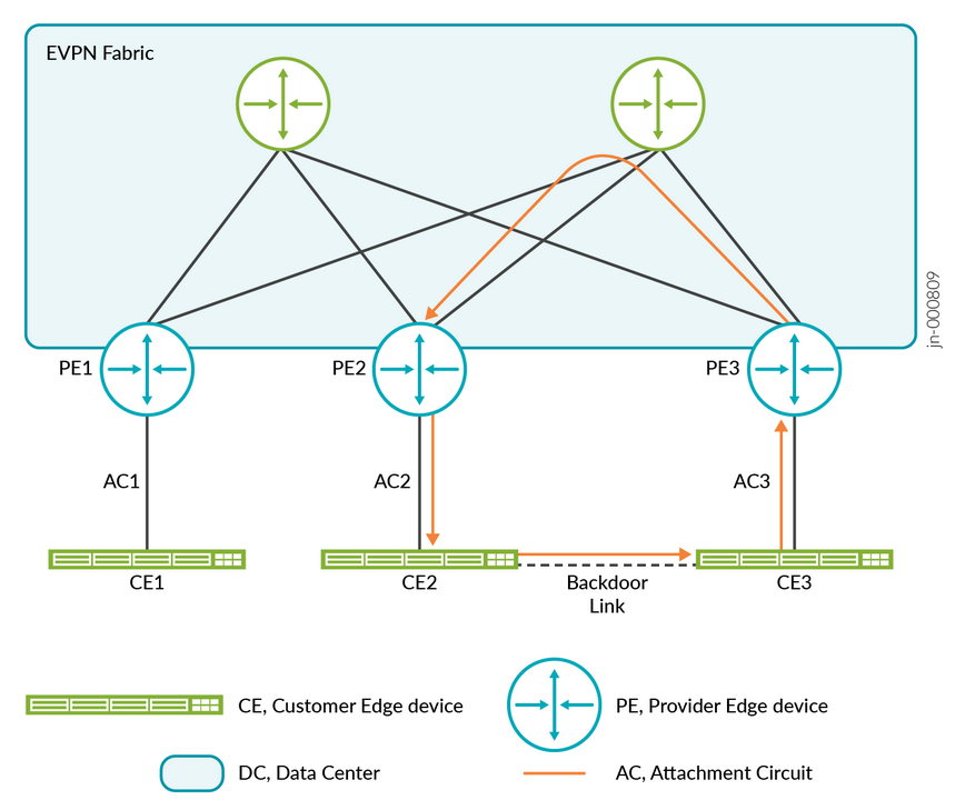
By default, EVPN fabrics typically treat MAC address movement as unusual behavior, since with wired clients this usually indicates something abnormal that should not occur. In the example below, a link between two fabric leaf switches could create a loop. To prevent this, one of the strategies used in EVPN fabrics is to detect when the same MAC address appears on multiple links. If this happens, the MAC address may be automatically blocklisted, and traffic associated with it will no longer be forwarded.
While automatic blocklisting of duplicate MAC addresses is useful for wired clients, it can create problems for wireless clients. Normal roaming behavior, where a client moves between APs connected to different leaf nodes in the EVPN fabric, may appear as a duplicate MAC event. This can cause the freshly roamed MAC address to be blocklisted, even though the behavior is legitimate.
To prevent this issue and ensure proper roaming for wireless clients, two approaches can be considered:
- By design: When using a centralized (tunneled) approach with Juniper Mist Edge integrated into the EVPN fabric, roaming does not appear as a duplicate MAC event. This is because all access points terminate their overlay tunnels on the Juniper Mist Edge, so the EVPN fabric always sees the client MAC address on the same upstream Mist Edge interfaces, regardless of which AP the client is connected to.
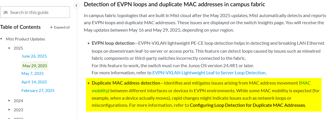
- Relaxing the default parameters for duplicate MAC address detection: Juniper EVPN fabrics enable administrators to adjust the detection window and related parameters (please review). Starting May 29, 2025, all newly created EVPN fabrics automatically use relaxed settings based on recommended best practices. With these defaults in place, wireless client roaming is supported without requiring additional configuration.
Older fabrics need the additional CLI commands listed below depending on fabric underlay and device type. Please do not change the parameters configured here as they are recommended best practice.
# Duplicate MAC detection relaxation for fabric ipv4-undelay
set groups top protocols evpn duplicate-mac-detection auto-recovery-time 5 detection-threshold 10 detection-window 20
#
# Duplicate MAC detection relaxation for fabric ipv6-undelay or physical ex92xx or vJunos-switch
set groups top routing-instances evpn_vs protocols evpn duplicate-mac-detection auto-recovery-time 5 detection-threshold 10 detection-window 20
Even when using the centralized approach with Juniper Mist Edge, it is recommended to verify that duplicate MAC address relaxation is enabled. This ensures proper handling in cases where APs terminate their tunnels on Juniper Mist Edges in different clusters and wireless clients attempt to roam between them.
Building a Hybrid Lab with Two Juniper Mist Edges and ESI-LAG Fabric Attach
The recommended method for integrating Juniper Mist Edge is to connect it at the service-block function of the fabric on the northbound side. It should not be connected at the access switch layer, since access switches typically lack the resources and capacity to manage the required traffic.
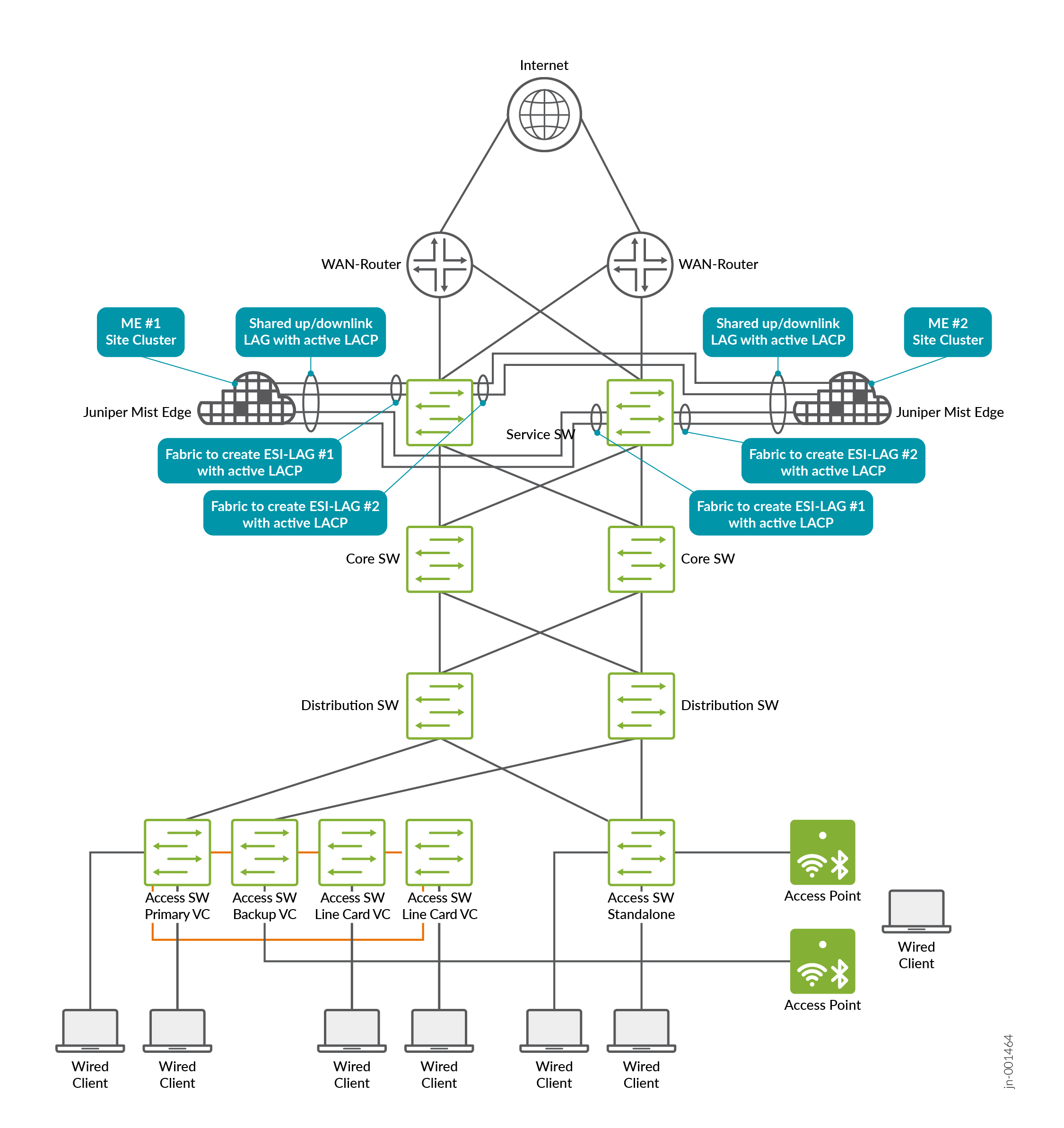
Integration should take advantage of the redundancy features provided by the EVPN fabric. This involves using ESI-LAG connections to the Juniper Mist Edge and enabling active LACP on both ends for link monitoring. The diagram below illustrates this approach using the example of a standard server integration.
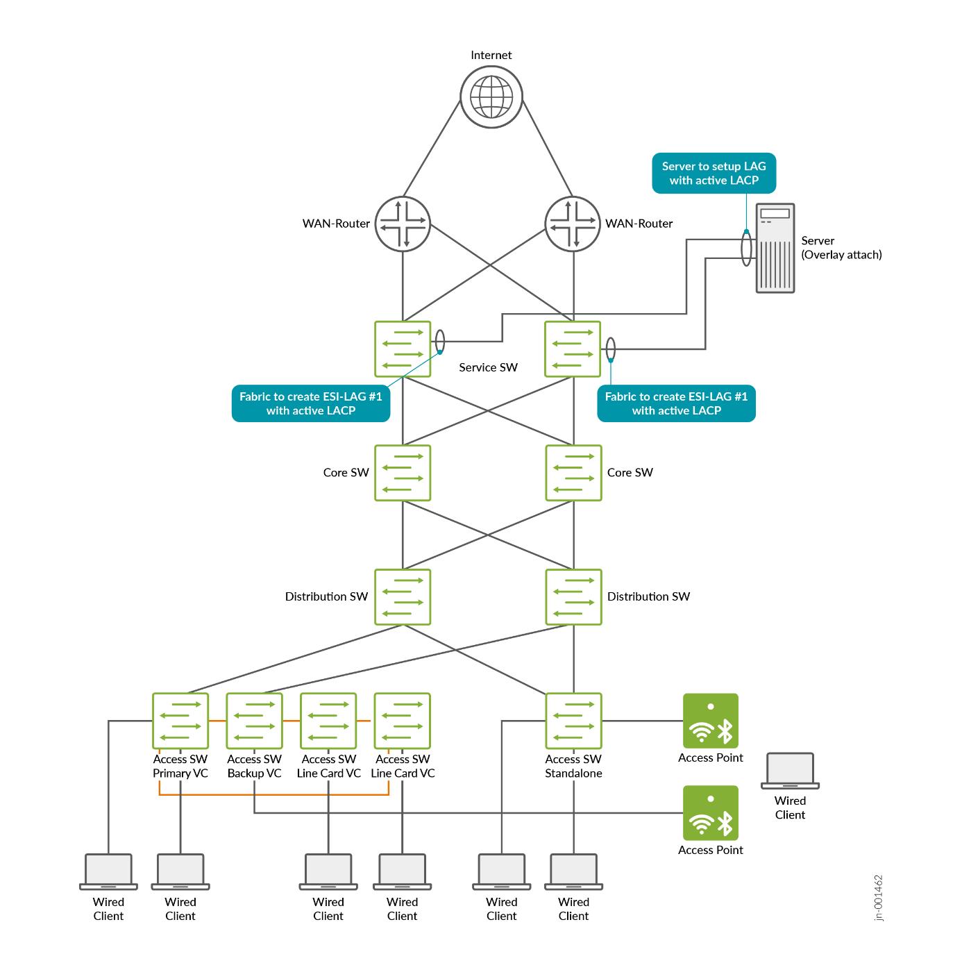
Juniper Mist Edge offers several other integration options, but these should be disregarded for campus fabric deployments. The proper method is to integrate using ESI-LAG on the fabric side and a single LAG on the Juniper Mist Edge, with both upstream and downstream interfaces multiplexed through that connection.In this lab design, we follow the recommended minimum of deploying two Juniper Mist Edges to provide redundancy in case one becomes unavailable, and we place both units in a single cluster. All APs in the EVPN fabric are assigned to a single AP site (the switch site assignments may differ, but that does not matter for this scenario). It is also required to enable the Shuffle-by-Site feature. With this enabled, one of the two Mist Edges is chosen to handle tunnel termination during normal operation, while the other remains on standby and automatically takes over if the primary unit becomes unreachable from the APs.Important note: When all Mist Edges reside in a single cluster, it is essential to prevent APs from distributing their tunnels across both Mist Edges. Although an active/active approach might appear beneficial, it can lead to unnecessary MAC address movement between two ESI-LAGs in the fabric when wireless clients roam between APs anchored on different Mist Edges. Active/active designs should only be used when mobility domains are separated, as explained in the next section on scale-out strategies.
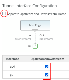
Juniper Mist Edge devices can provide either two or four uplink interfaces for tunnel operation, depending on the model. The setup shown below illustrates a lab design recommended for Juniper Mist Edges that support two uplink interfaces for tunnel operation:
When setting up Juniper Mist Edge, the LAG and active LACP configurations are not directly specified in the Juniper Mist portal. To configure this, disable the separate upstream and downstream operation and instead enable both upstream and downstream interfaces together, as shown in the image below:
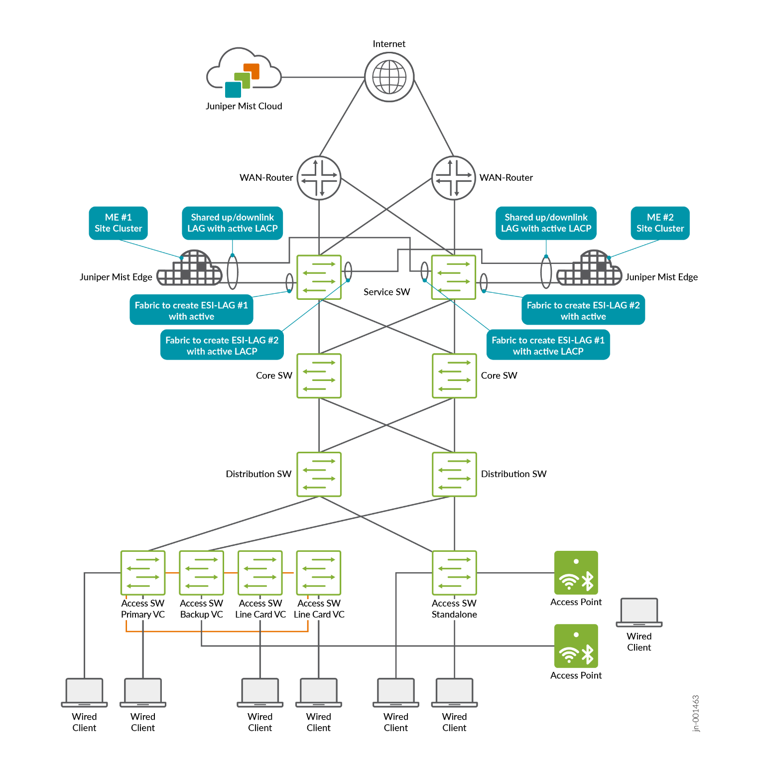
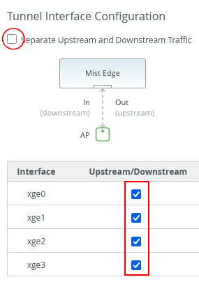
Here's a suggested lab setup for Juniper Mist Edges, which have four revenue interfaces for tunnel operation:
When setting up Juniper Mist Edge, the LAG and active LACP configurations are not directly specified in the Juniper Mist portal. To configure this, disable the separate upstream and downstream operation and instead enable both upstream and downstream interfaces together, as shown in the image below:
Lab Preparation
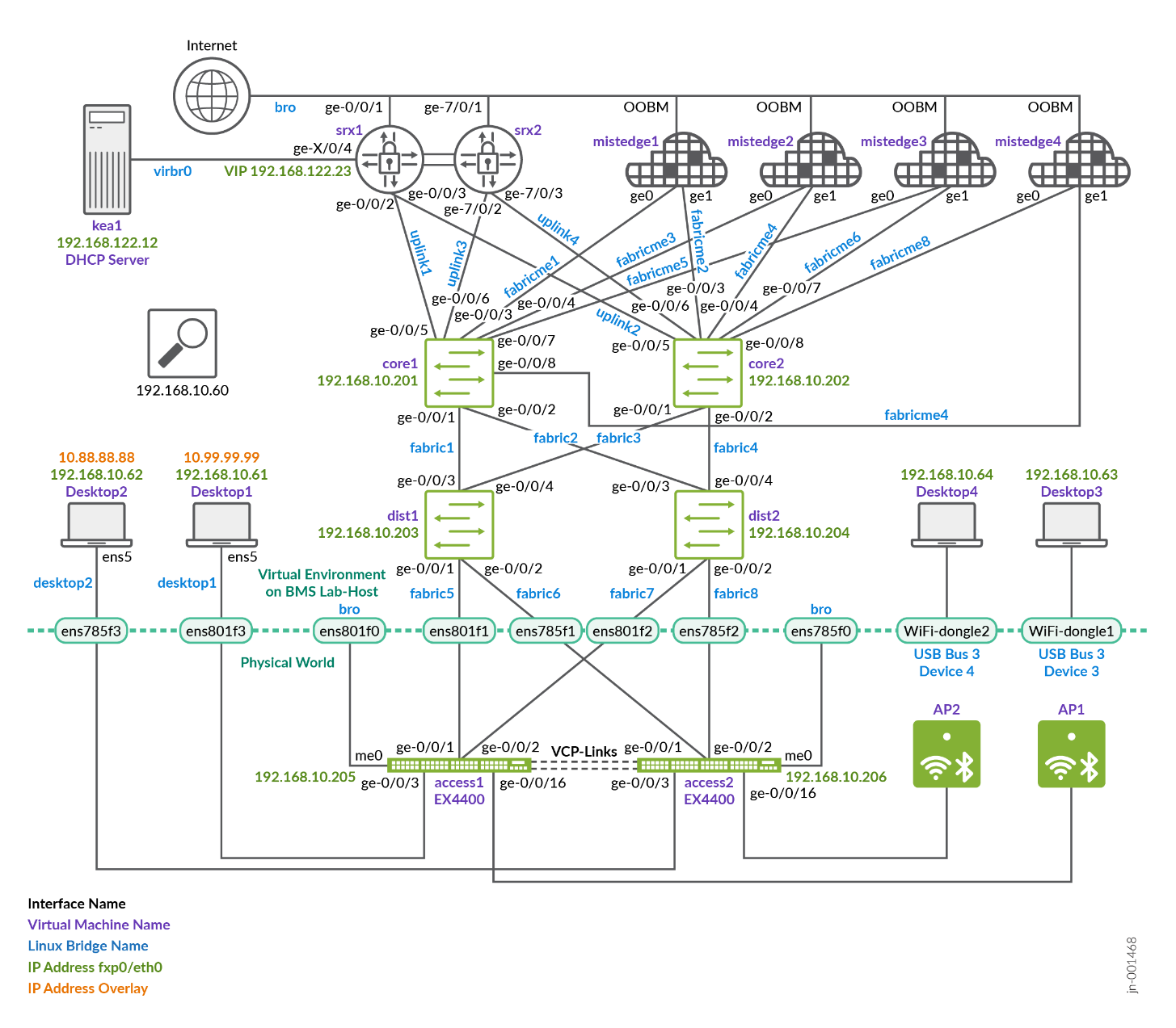
This lab was constructed to show the functionality with the fewest physical devices required. It is not intended for use in a production environment. The integration of vJunos-switch VMs with Mist Cloud is described here.
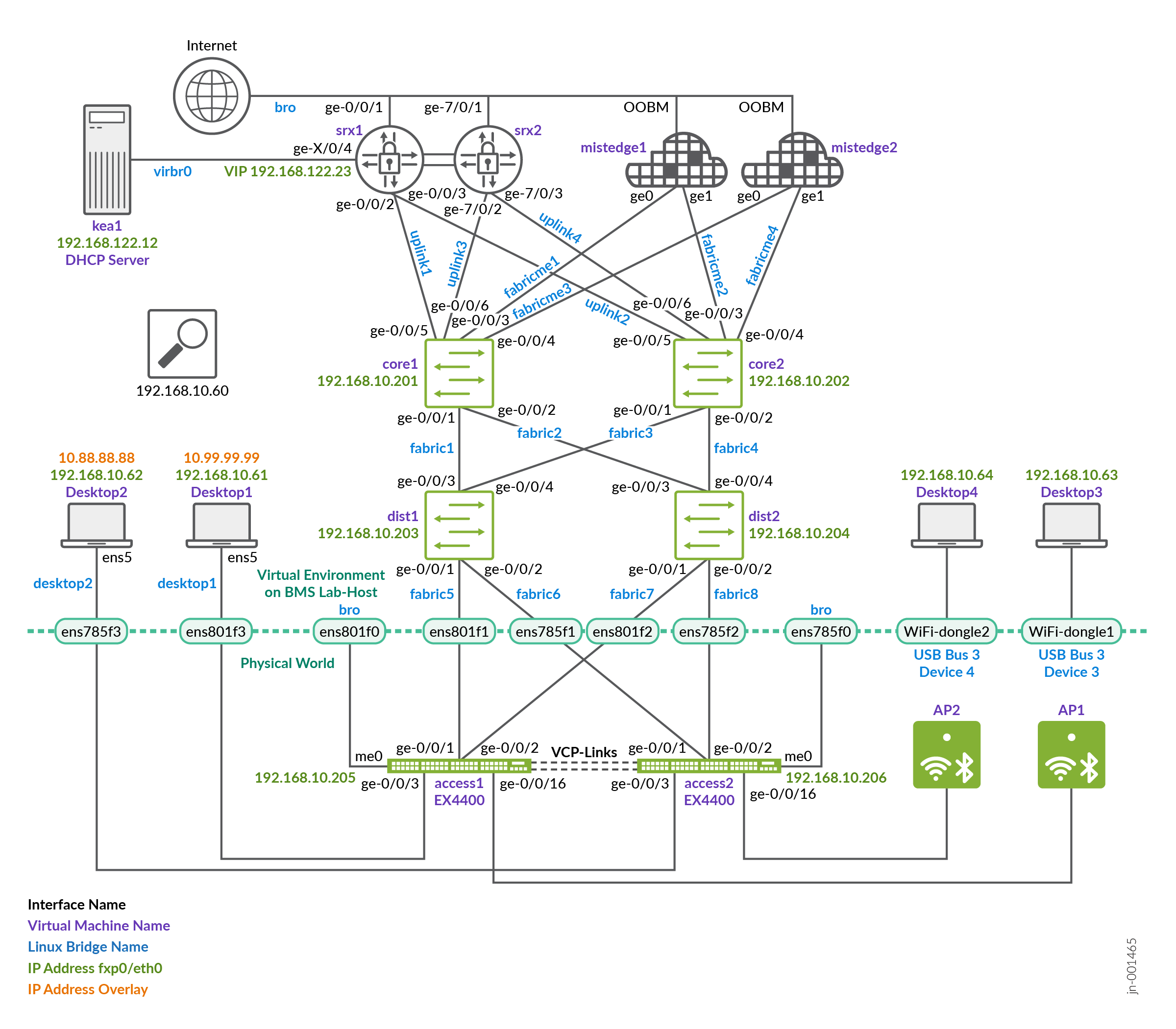
The lab described here was not built with physical Juniper Mist Edge devices. Instead, we used a combination of virtual machines and physical hardware, particularly because APs cannot be virtualized. The two additional access switches in this setup are also physical devices, which allows us to utilize Virtual Chassis and VXLAN group-based policy (GBP) functionality.
The Juniper Mist Edge virtual machine does not support LACP on LAGs when deployed as a VM. When LACP is configured on the LAG of the VM, the LACP configuration is automatically suppressed in the backend and not applied to the VM. This limitation exists because LAG configurations are typically handled at the hypervisor level on the host operating system. For our lab environment, we configure it as a physical ME-X1 device to overcome this restriction.
The topology above the service-block switches is part of the core network, with two Juniper Mist Edge devices connected to each core switch. Each Juniper Mist Edge has its own dedicated ESI-LAG configuration. The design concept for this setup is as follows:
- VLAN 1033 with subnet 10.33.33.0/24 is assigned as the
native/access VLAN for the APs, allowing them to boot properly.
Only a single native VLAN is required for the AP, since all SSID
VLANs are tunneled through the Juniper Mist Edge. This VLAN serves
multiple purposes:
- It provides the AP with a DHCP lease for booting.
- It allows the AP to communicate with the Juniper Mist cloud for management.
- It enables the AP to establish a tunnel to one of the two Juniper Mist Edge devices, carrying all VLANs associated with SSIDs via default gateway in the next VLAN.
- VLAN 1011 with subnet 10.11.11.0/24. This is the network in which the Juniper Mist Edges have static IP addresses for tunnel termination from the AP. VLANs 1099 and 1088 are assigned to a specific SSID that wireless clients can connect to. The traffic for these VLANs is tunneled from the AP to the Juniper Mist Edge using a proprietary L2TPv3 tunnel. The tunneled traffic is then presented as an L2 VLAN trunk and reinserted into the fabric through a service block, allowing it to be mapped into the appropriate VRFs.
- VLANs 1091 and 1081 will be used for wired clients.
If not already completed, perform the steps for IP Clos fabric creation, DHCP relay configuration, and WAN router integration as described in the appendix above.
Juniper Mist Edge and Fabric Configuration
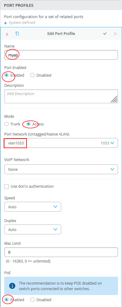
In the switch template, a port profile is configured to connect the AP to the access switch. Since forwarding is handled through the Juniper Mist Edge, only VLAN 1033 needs to be set as the access VLAN.
Navigate to Switch Template and configure a new port profile:
- Name=
myap - Port Enabled=
Enabled - Mode=
Access - Port Network=
vlan1033 - PoE=
Enabled
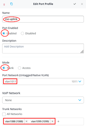
Next, a port profile is required for the links on the service-block switches (core1 and core2 in this example). The AP tunnel is carried as the native VLAN, while the VLANs for wireless client breakout are configured as tagged VLANs.
Navigate to Switch Template and configure a new port profile:
- Name=
me-uplink - Port Enabled=
Enabled - Mode=
Trunk - Port Network=
vlan1011 - Trunk Networks=
vlan1088andvlan1099
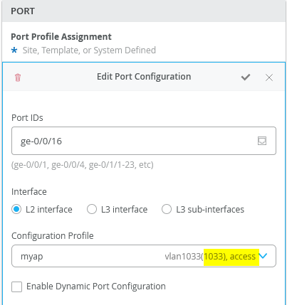
The configuration of Access-Switch1 and Access-Switch2 for wired and access ports have the following port profile created:
Then, on Access-Switch1 and Access-Switch2, apply this port profile on all ports connected to an AP:
- Port IDs=
ge-0/0/16 - Configuration Profile=
myap
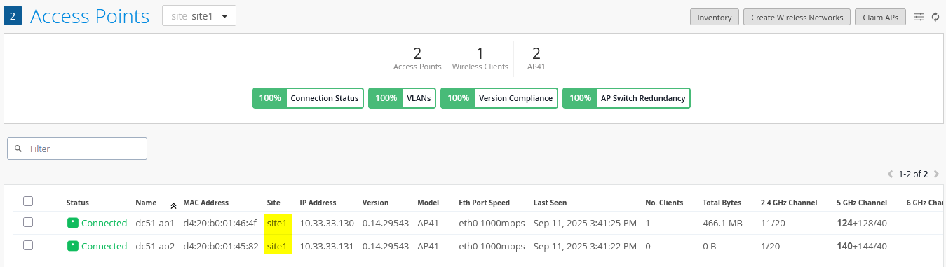
Check that your APs are coming up now and are seen in Juniper Mist cloud as they should now get a DHCP lease and are able to contact Juniper Mist cloud.
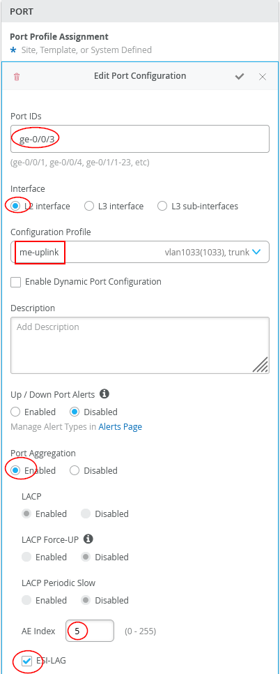
Next, configure core1 and core2 which perform the service-block functions.
The configuration of Core1-Switch and Core2-Switch for the first Juniper Mist Edge is:
- Port ID=
ge-0/0/3 - Interface=
L2 interface - Configuration Profile=
me-uplink - Port Aggregation=
Enabled- AE Index=
5(you need to ensure this index value is unique and only used on the interface towards the same Juniper Mist Edge) - ESI-LAG=
Enabled(enabling this is mandatory)
- AE Index=
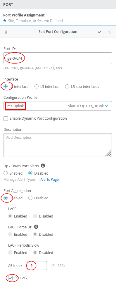
The configuration of Core1-Switch and Core2-Switch for the second Juniper Mist Edge is:
- Port ID=
ge-0/0/4 - Interface=
L2 interface - Configuration Profile=
me-uplink - Port Aggregation=
Enabled- AE Index=
6(you need to ensure this index value is only used on the interface towards the same Juniper Mist Edge) - ESI-LAG=
Enabled(Enabling this is mandatory)
- AE Index=
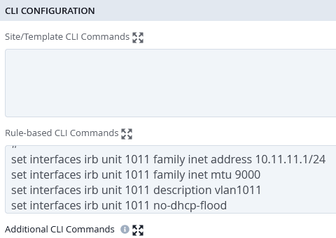
As of July 2025, the Juniper Mist cloud does not automatically configure default gateways or DHCP relay for a VLAN and VRF at the service-block function. This feature may be included in a future release, but for now, these configurations must be added manually using additional CLI commands. To determine what needs to be configured, it is recommended that for IP Clos fabrics you first set up a VLAN for wireless clients on a port of one of your access switches. You can then copy the IRB and DHCP relay settings to the service-block switches. The following example illustrates this process for our fabric:
Consider a maintenance window of your EVPN Fabric when testing the below additional Junos CLI.
For VLAN 1011, which is used to establish the tunnel from the AP to the Juniper Mist Edge, configuring the default gateway is required. DHCP relay is not necessary, since the connected Juniper Mist Edges are always assigned static IP addresses.
set interfaces irb unit 1011 family inet address 10.11.11.1/24
set interfaces irb unit 1011 family inet mtu 9000
set interfaces irb unit 1011 description vlan1011
set interfaces irb unit 1011 no-dhcp-flood
set interfaces irb unit 1011 mac 00:00:5e:e4:31:57
#
set groups top routing-instances evpn_vs vlans vlan1011 l3-interface irb.1011
set groups top routing-instances devices interface irb.1011
Depending on your service block function configuration and what is attached, you might be able to automatically include large portions of the required DHCP relay configuration onto the VRF at the service-block function. Usually, when you check the configuration of your service-block switch, the DHCP relay will be disabled as shown in the image below.
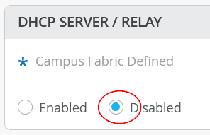
This is due to the assumption that clients typically obtain DHCP leases only through an access switch. Servers connected through an ESI-LAG at a service-block function usually rely on static IP addresses. However, as an exception, you can override this behavior by enabling the option and then manually configuring DHCP relay for your wireless client breakout networks.
An issue that can occur when enabling DHCP relay on a VRF is that clients connected to the EVPN fabric access switches using that same VRF may suddenly be unable to obtain a DHCP lease!
This behavior can occur depending on the Junos release in use, because enabling the DHCP relay agent installs hidden traffic filters within the VRF. These filters may inadvertently block DHCP relay packets coming from access switches, even when they are simply passing through the VRF along with locally generated traffic. To avoid or resolve this, you can use one of the following approaches:
- If the service-block function switch is a physical device, add
an additional Junos configuration such as
set groups top
routing-instances <vrf> forwarding-options dhcp-relay
no-snoop
- If the service-block function is running on a virtual switch VM and the above adjustment does not work, it is recommended to separate the VLAN used by clients on access switches into one VRF, and place all wireless clients into another VRF. By doing this, the DHCP relay configuration on the service block will not interfere with other VRFs.
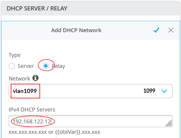
This is the configuration needed for wireless client breakout for VLAN 1099:
set interfaces irb unit 1099 family inet address 10.99.99.1/24
set interfaces irb unit 1099 family inet mtu 9000
set interfaces irb unit 1099 description vlan1099
set interfaces irb unit 1099 no-dhcp-flood
set interfaces irb unit 1099 mac 00:00:5e:e4:31:57
#
set groups top routing-instances evpn_vs vlans vlan1099 l3-interface irb.1099
set groups top routing-instances customera interface irb.1099
#
set groups top routing-instances customera forwarding-options dhcp-relay server-group vlan1099 192.168.122.12
set groups top routing-instances customera forwarding-options dhcp-relay group vlan1099 interface irb.1099
set groups top routing-instances customera forwarding-options dhcp-relay group vlan1099 active-server-group vlan1099
set groups top routing-instances customera forwarding-options dhcp-relay group vlan1099 relay-option-82 circuit-id vlan-id-only
set groups top routing-instances customera forwarding-options dhcp-relay group vlan1099 relay-option-82 server-id-override
set groups top routing-instances customera forwarding-options dhcp-relay group vlan1099 route-suppression destination
set groups top routing-instances customera forwarding-options dhcp-relay group vlan1099 overrides relay-source lo0.1
set groups top routing-instances customera forwarding-options dhcp-relay forward-only
set groups top routing-instances customera forwarding-options dhcp-relay no-snoop
This is the configuration needed for wireless client breakout for VLAN 1088:
set interfaces irb unit 1088 family inet address 10.88.88.1/24
set interfaces irb unit 1088 family inet mtu 9000
set interfaces irb unit 1088 description vlan1088
set interfaces irb unit 1088 no-dhcp-flood
set interfaces irb unit 1088 mac 00:00:5e:e4:31:57
#
set groups top routing-instances evpn_vs vlans vlan1088 l3-interface irb.1088
set groups top routing-instances customerb interface irb.1088
#
set groups top routing-instances customerb forwarding-options dhcp-relay server-group vlan1088 192.168.122.12
set groups top routing-instances customerb forwarding-options dhcp-relay group vlan1088 interface irb.1088
set groups top routing-instances customerb forwarding-options dhcp-relay group vlan1088 active-server-group vlan1088
set groups top routing-instances customerb forwarding-options dhcp-relay group vlan1088 relay-option-82 circuit-id vlan-id-only
set groups top routing-instances customerb forwarding-options dhcp-relay group vlan1088 relay-option-82 server-id-override
set groups top routing-instances customerb forwarding-options dhcp-relay group vlan1088 route-suppression destination
set groups top routing-instances customerb forwarding-options dhcp-relay group vlan1088 overrides relay-source lo0.2
set groups top routing-instances customerb forwarding-options dhcp-relay forward-only
set groups top routing-instances customerb forwarding-options dhcp-relay no-snoop
The line containing “l3-interface” includes the statement “routing-instances evpn_vs” only because our core switches are vJunos-switch VMs. Be sure to verify the correct configuration for your own fabric and deployment.
In our setup, this is added by defining a role in the switch template for the additional CLI commands and assigning that role to core1 and core2. The statements then appear as rule-based CLI commands. Alternatively, additional CLI commands can be added individually on each switch.
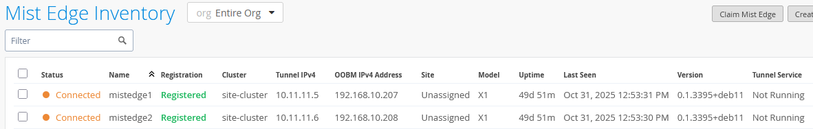
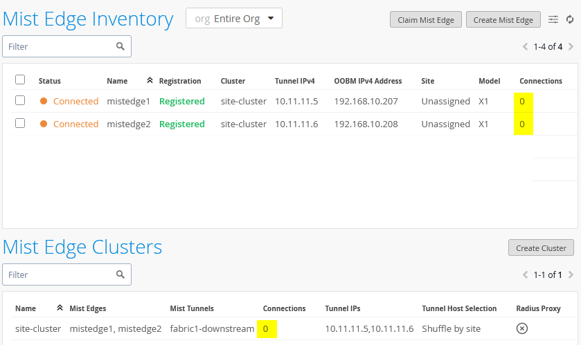
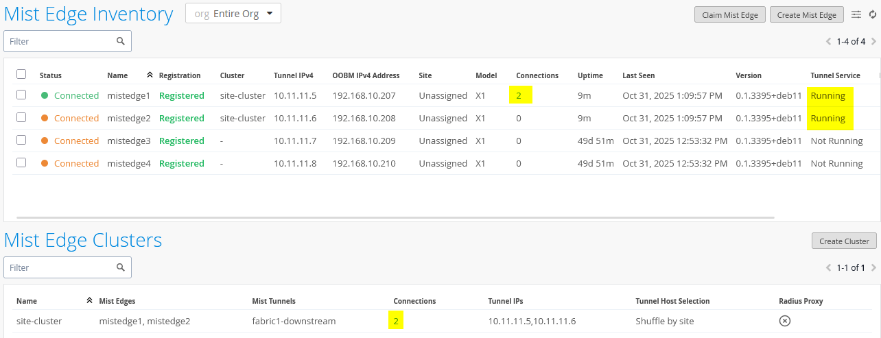
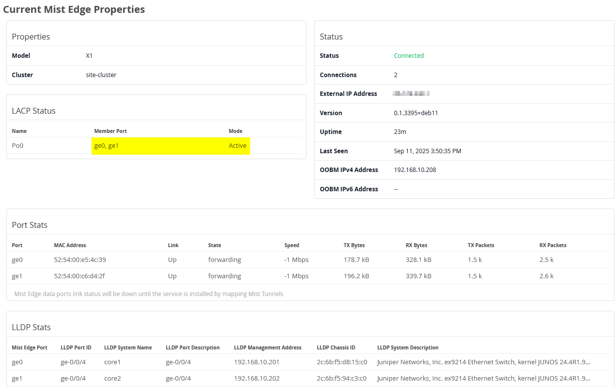
Next, we will configure the Juniper Mist Edge. The image below shows the state after the lab has been set up, with the two Juniper Mist Edge VMs launched and registered in the Juniper Mist cloud using the provided registration code.
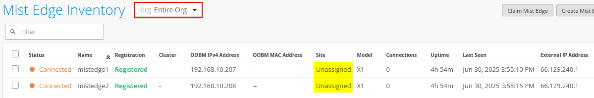
In this example, the Juniper Mist Edges are used at the global level and are not assigned to a specific site, so they appear as “unassigned.” Larger organizations may choose to assign Mist Edges to a site and configure tunnels through the Organization -> Site Configuration option. This approach was not implemented in our example because we wanted to demonstrate how the Shuffle-by-Site feature operates.
Next, we configure the first Juniper Mist Edge as follows:
- Name=
mistedge1 - IP=
10.11.11.5(remember our AP’s vlan should be different from Mist-Edge VLAN used) - Netmask=
/24 - Gateway=
10.11.11.1 - Separate Upstream and Downstream
Traffic=
Unchecked - Interface ge0=
Checked - Interface ge1=
Checked - DHCP Relay=
Unchecked
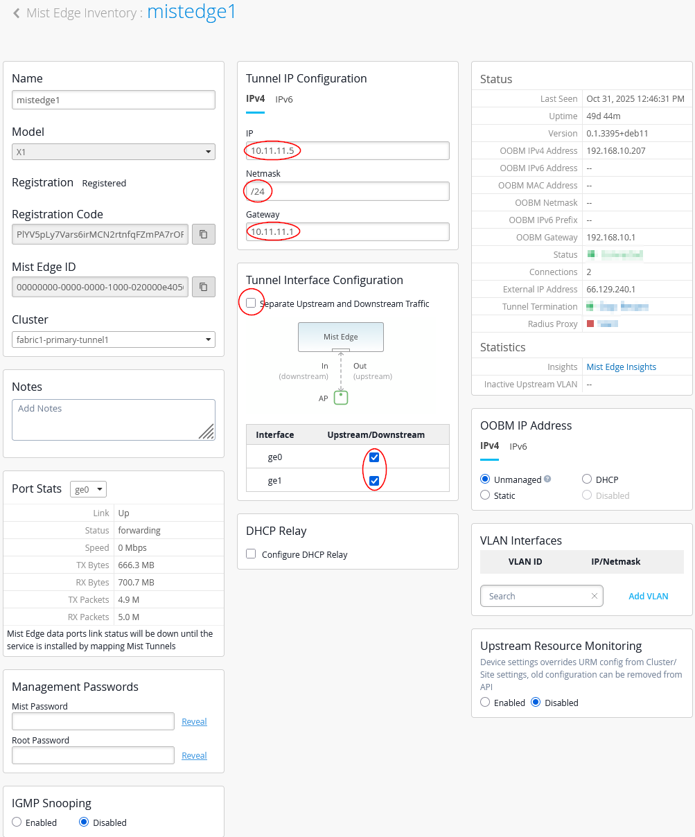
Do not configure DHCP relay directly on the Juniper Mist Edge. The fabric is set up to handle this traffic through the VRF at the service-block function.
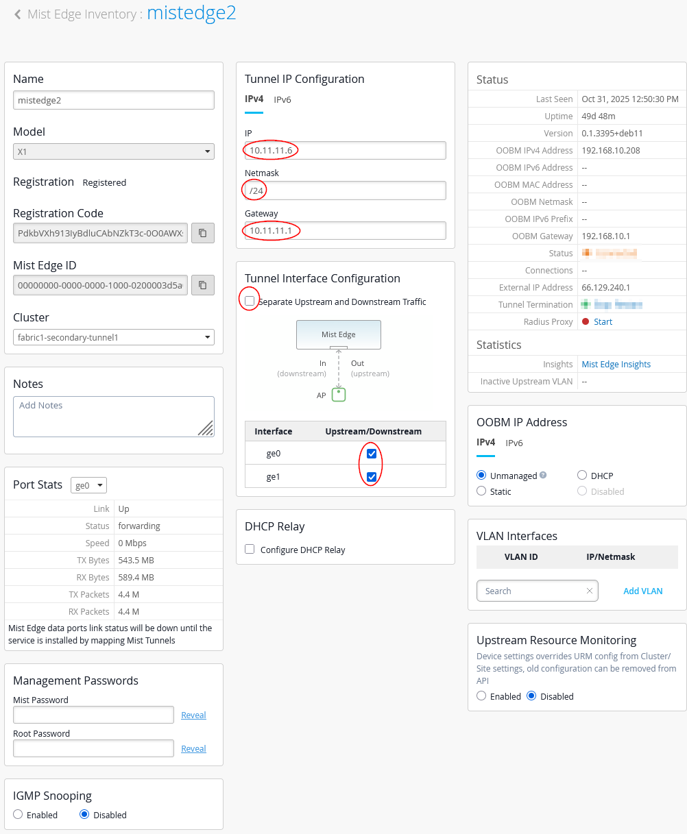
Next, we configure the second Juniper Mist Edge as follows:
- Name=
mistedge2 - IP=
10.11.11.6(remember our AP’s vlan should be different from Mist-Edge VLAN used) - Netmask=
/24 - Gateway=
10.33.33.1 - Separate Upstream and Downstream
Traffic=
Unchecked - Interface ge0=
Checked - Interface ge1=
Checked - DHCP Relay=
Unchecked
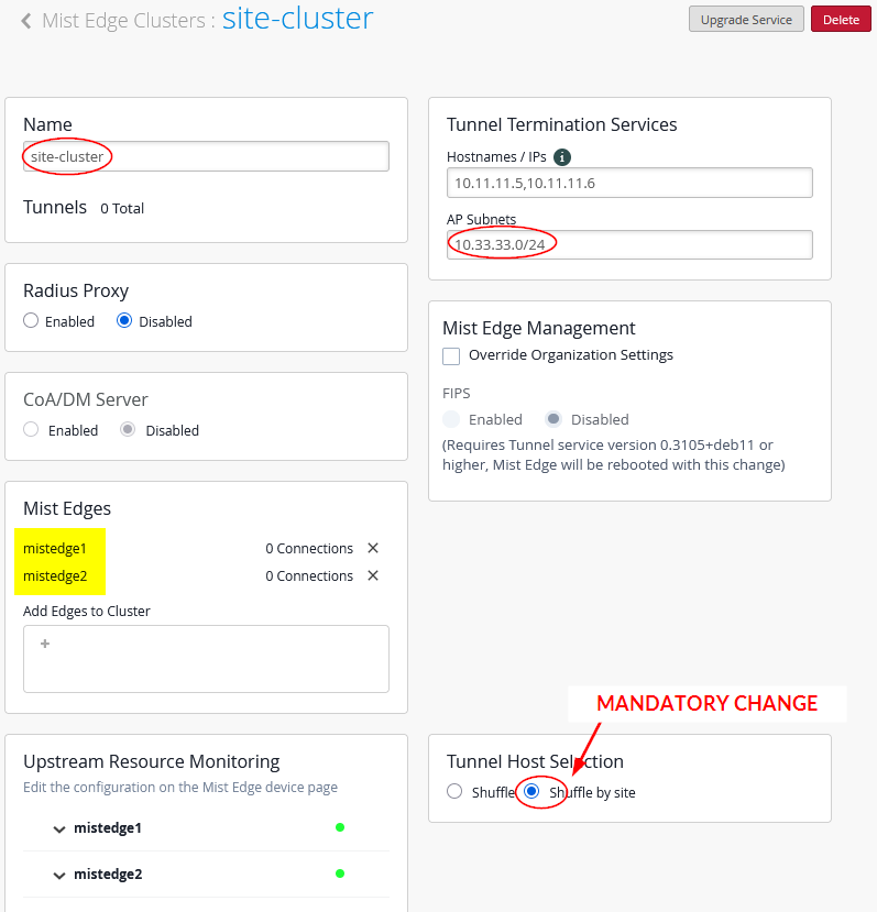
Then, we configure our Mist Edge cluster with the two Mist Edges inside.
- Name=
site-cluster - Mist Edges=
mistedge1andmistedge2 - Hostnames / IPs=
10.11.11.5,10.11.11.6(happens automatically when assigning the Juniper Mist Edge) - AP Subnets=
10.33.33.0/24(This configuration is optional. With it enabled, the Juniper Mist Edge will only accept tunnels if the AP’s source IP address falls within the range assigned to VLAN 1033) - Tunnel Host Selection=
Shuffle by Site(This configuration is required and ensures that all APs within the same site or fabric use the same Juniper Mist Edge)
Your cluster assignment should now be visible on the Juniper Mist Edges:
The created cluster should look like the image shown below:
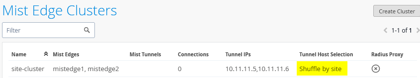
Do not continue without selecting “Shuffle-by-site” on your cluster! It is important to instruct the APs to use a single Juniper Mist Edge as long as possible in this design.
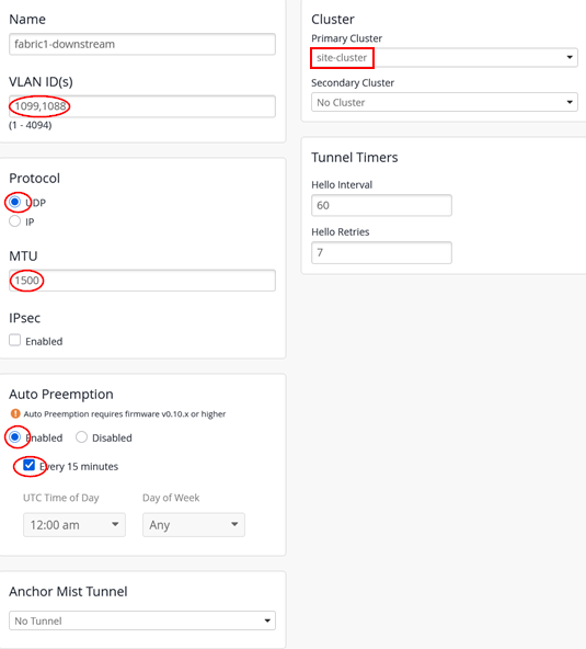
Next, the configuration of the overlay tunnel from the AP to the Juniper Mist Edge (in our case in vlan1033):
- Name=
fabric1-downstream - VLAN ID=
1099, 1088(depending on all your breakout VLANs for wireless client traffic) - Primary Cluster=
site-cluster - Secondary Cluster=
No Cluster - Protocol=
UDP - MTU=
1500 - IPsec=
Unchecked - Auto Preemption=
Enabled(If an AP accidentally roams to the second Juniper Mist Edge while the primary Edge is still active and managing the other APs, the AP will automatically roam back to the primary.) - Every 15 minutes=
Checked(roaming back should happen as fast as possible, hence this configuration)
The configuration you entered should result in the overview shown below:
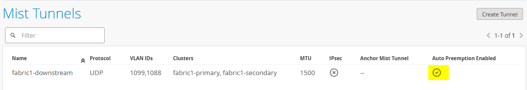
At this point, no APs are connecting to the Juniper Mist Edges because the tunnel configuration has not yet been specified for them:
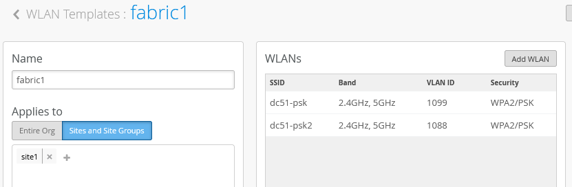
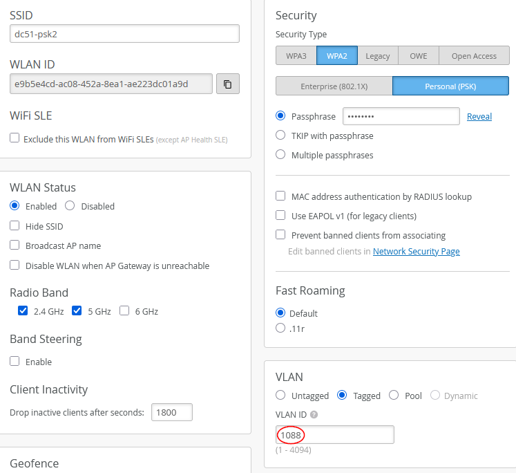
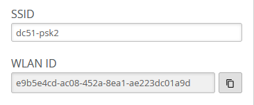
As a last configuration step, we need to configure the WLAN template with the information about the tunnel configuration. Here is our fabric template with two SSIDs configured:
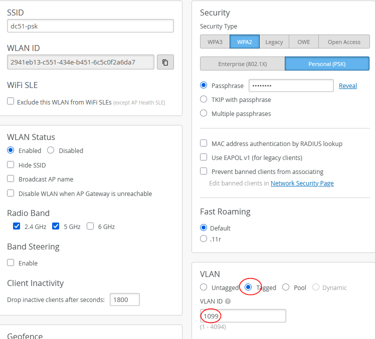
The configuration for our first SSID is a simple PSK. You need to configure one of the tunnel breakout VLANs as tagged as shown below:
- VLAN=
Tagged - VLAN ID=
1099
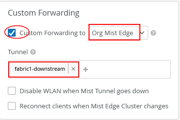
Now, the tunnel configuration for this SSID would look like:
- Custom Forwarding=
Checked - To=
Org Mist Edge - Tunnel=
fabric1-downstream
Do not enable the two additional features unless there is a specific need. Leave “Disable WLAN when Mist Tunnel goes down” and “Reconnect clients when Mist Edge Cluster changes” disabled as they are by default. These options are not required when Juniper Mist Edge is operating within an EVPN fabric, since tunnel distances are short and the new cluster typically uses upstream configurations where such features might otherwise be beneficial.
The configuration for our second SSID is again a simple PSK. You need to configure one of the tunnel breakout VLANs as tagged as shown below:
- VLAN=
Tagged - VLAN ID=
1088
Now, the tunnel configuration for this SSID should again look like the following:
- Custom Forwarding=
Checked - To=
Org Mist Edge - Tunnel=
fabric1-downstream
.png)
Also ensure that all your Access Points really belong to the same site in this design.
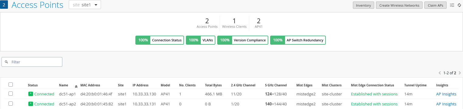
Once this final step is complete, the configuration is done. You should now see both APs connected to only one of the Juniper Mist Edges, as expected, since they are part of the same site and the Shuffle-by-Site option designates a specific Mist Edge for them. This confirms that the APs remain anchored to a single Mist Edge. You should also see that the tunnel service is active, indicating that the configuration is valid.
You also now have the AP View showing Juniper Mist Edge and Cluster:
And a report from a selected individual AP:
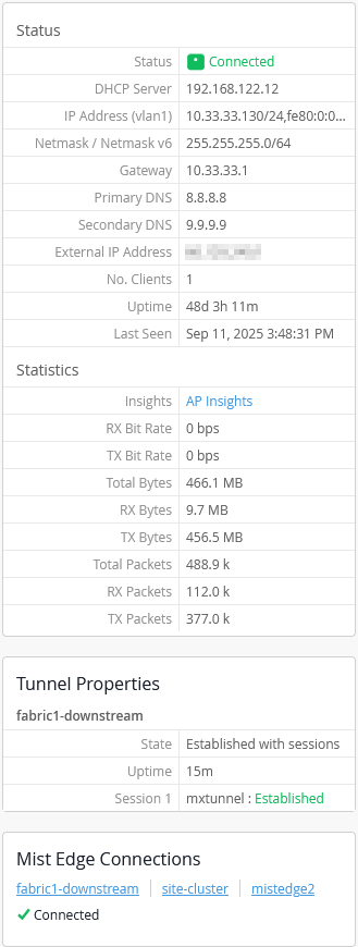
Also, review the Juniper Mist Edge insights as shown in the example below:
Alternative Configuration Option by Site Tunnel Creation
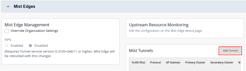
In this example, we used global Juniper Mist Edges along with a cluster that has the Shuffle-by-Site option enabled. However, this is not the only way to configure the system. You can also deploy the Mist Edges and establish the tunnel directly through the site settings without creating a cluster. To do this, navigate to Organization → Site Configuration → <site of your APs> and choose Add Tunnel.
This is our site tunnel configuration:
- VLAN ID=
1099, 1088(depending on all your breakout VLANs used for wireless client traffic) - Protocol=
UDP - AP Subnets=
10.33.33.0/24(optionally restricts tunnel termination to only those APs using this source IP ) - MTU=
1500 - IPsec=
Unchecked - Primary Cluster Enabled=
Checked/Enabled- Host IP=
10.11.11.5
- Host IP=
- Secondary Cluster Enabled=
Checked/Enabled- Host IP=
10.11.11.6
- Host IP=
- Auto Preemption=
Enabled(if an AP unintentionally roams to a second Mist Edge while the original remains active, it should return to the original Mist Edge along with the other APs)- Every 15 minutes=
Checked(roaming back should happen as fast as possible hence this configuration)
- Every 15 minutes=
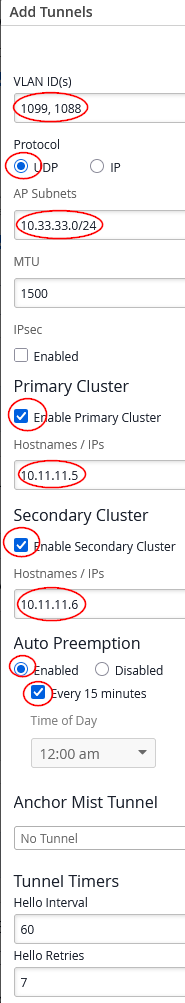
Since the Shuffle-by-Site option is not available at the site configuration level, you must manually specify a primary and secondary Juniper Mist Edge. This setup ensures that APs terminate their tunnels on a single designated Mist Edge within the EVPN fabric.
Testing Your Configuration
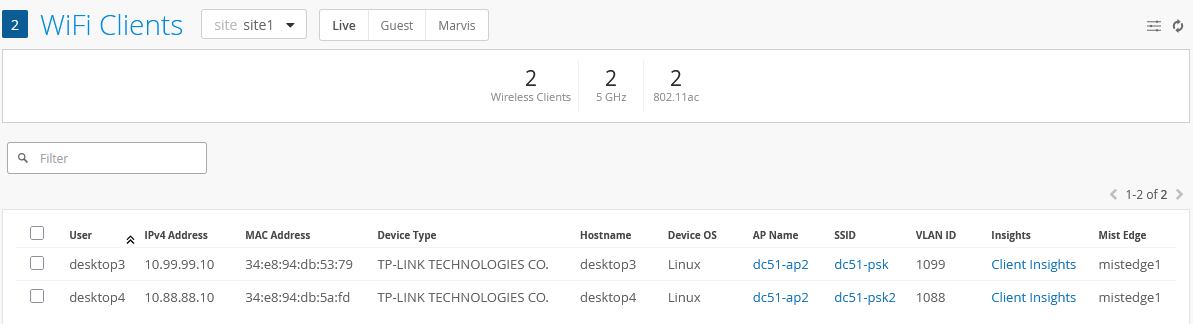
At this point, all required configurations are completed and you can launch your wireless client for testing. In our case:
- The Desktop3 VM connects to the SSID dc51-psk, is assigned to VLAN 1099 on the first VRF, and receives a DHCP lease.
- The Desktop4 VM connects to the SSID dc51-psk2, is assigned to VLAN 1088 on the second VRF, and receives a DHCP lease.
The two connected wireless clients are reported like this:
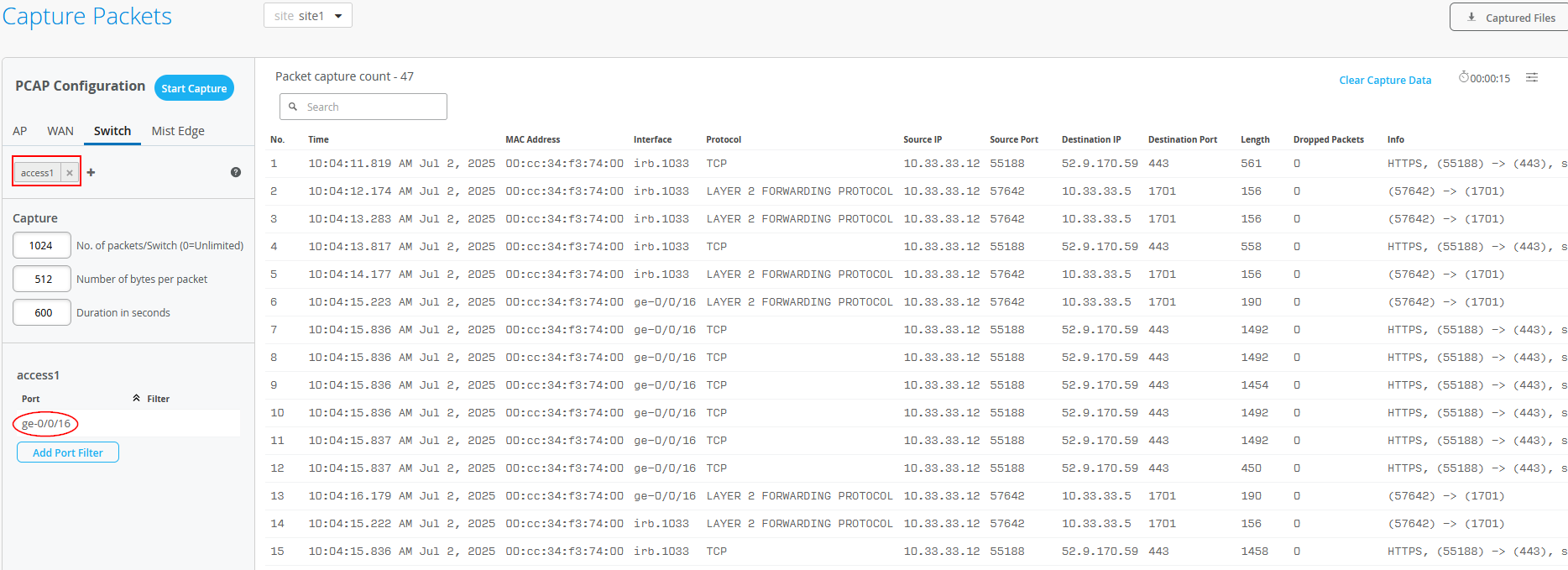
When using Site -> Switch Packet Captures in the Juniper Mist portal, you can capture traffic ingressing your switch port. Below, you see a trace taken from the interface where the AP is attached to the Access1 switch. You can see the HTTPS communication with the AP towards the Juniper Mist cloud as well as the L2TPv3 tunnel towards the local Juniper Mist Edge.
The output below is gathered from the Core1 switch acting as the service block for the integration of the two Juniper Mist Edges:
root@core1> show lldp neighbors
Local Interface    Parent Interface    Chassis Id                               Port
.
ge-0/0/1           -                   2c:6b:f5:5e:9a:c0                        evpn_uplink-to-0200043ef581 dist1
ge-0/0/2           -                   2c:6b:f5:d9:94:c0                        evpn_uplink-to-0200043ef581 dist2
ge-0/0/3           ae5                 562537d5-60c9-45cd-9883-93bd614382d3     port0               mistedge1
ge-0/0/4           ae6                 fbed3379-875a-4329-a957-03c64788d8ef     port0               mistedge2
.
root@core1> show lacp interfaces
.
.
Aggregated interface: ae5
    LACP state:           Role   Exp   Def  Dist  Col  Syn  Aggr  Timeout  Activity
      ge-0/0/3           Actor    No    No   Yes  Yes  Yes   Yes     Fast    Active
      ge-0/0/3         Partner    No    No   Yes  Yes  Yes   Yes     Fast    Active
    LACP protocol:        Receive State  Transmit State          Mux State
      ge-0/0/3                  Current   Fast periodic Collecting distributing
Aggregated interface: ae6
    LACP state:           Role   Exp   Def  Dist  Col  Syn  Aggr  Timeout  Activity
      ge-0/0/4           Actor    No    No   Yes  Yes  Yes   Yes     Fast    Active
      ge-0/0/4         Partner    No    No   Yes  Yes  Yes   Yes     Fast    Active
    LACP protocol:        Receive State  Transmit State          Mux State
      ge-0/0/4                  Current   Fast periodic Collecting distributing
.
root@core1> show ethernet-switching table
MAC flags (S - static MAC, D - dynamic MAC, L - locally learned, P - Persistent static, C - Control MAC
           SE - statistics enabled, NM - non configured MAC, R - remote PE MAC, O - ovsdb MAC,
           B - Blocked MAC)
.
Ethernet switching table : 14 entries, 14 learned
Routing instance : evpn_vs
   Vlan                MAC                 MAC       GBP    Logical                SVLBNH/      Active
   name                address             flags     tag    interface              VENH Index   source
.
   vlan1033            d4:20:b0:01:45:82   DR               vtep.32769                          172.16.254.6
   vlan1033            d4:20:b0:01:46:4f   DR               vtep.32770                          172.16.254.5
   vlan1033            fa:13:47:b8:a3:c6   DLR              ae5.0
   vlan1033            fe:54:00:42:27:e4   DR               ae6.0
   vlan1088            34:e8:94:db:5a:fd   DLR              ae5.0
   vlan1088            52:54:00:3d:91:08   DR               vtep.32769                          172.16.254.6
   vlan1099            1c:fd:08:77:93:4b   DR               vtep.32770                          172.16.254.5
   vlan1099            52:54:00:2c:80:63   DR               vtep.32770                          172.16.254.5
The below is gathered from the Core2 switch acting as the service block for the integration of the two Juniper Mist Edges:
root@core2> show lldp neighbors
Local Interface    Parent Interface    Chassis Id                               Port info          System Name
.
ge-0/0/1           -                   2c:6b:f5:5e:9a:c0                        evpn_uplink-to-020004070deb dist1
ge-0/0/2           -                   2c:6b:f5:d9:94:c0                        evpn_uplink-to-020004070deb dist2
ge-0/0/3           ae5                 562537d5-60c9-45cd-9883-93bd614382d3     port1               mistedge1
ge-0/0/4           ae6                 fbed3379-875a-4329-a957-03c64788d8ef     port1               mistedge2
.
root@core2> show lacp interfaces
.
.
Aggregated interface: ae5
    LACP state:           Role   Exp   Def  Dist  Col  Syn  Aggr  Timeout  Activity
      ge-0/0/3           Actor    No    No   Yes  Yes  Yes   Yes     Fast    Active
      ge-0/0/3         Partner    No    No   Yes  Yes  Yes   Yes     Fast    Active
    LACP protocol:        Receive State  Transmit State          Mux State
      ge-0/0/3                  Current   Fast periodic Collecting distributing
Aggregated interface: ae6
    LACP state:           Role   Exp   Def  Dist  Col  Syn  Aggr  Timeout  Activity
      ge-0/0/4           Actor    No    No   Yes  Yes  Yes   Yes     Fast    Active
      ge-0/0/4         Partner    No    No   Yes  Yes  Yes   Yes     Fast    Active
    LACP protocol:        Receive State  Transmit State          Mux State
      ge-0/0/4                  Current   Fast periodic Collecting distributing
root@core2> show ethernet-switching table
.
MAC flags (S - static MAC, D - dynamic MAC, L - locally learned, P - Persistent static, C - Control MAC
           SE - statistics enabled, NM - non configured MAC, R - remote PE MAC, O - ovsdb MAC,
           B - Blocked MAC)
.
Ethernet switching table : 15 entries, 15 learned
Routing instance : evpn_vs
   Vlan                MAC                 MAC       GBP    Logical                SVLBNH/      Active
   name                address             flags     tag    interface              VENH Index   source
.
   vlan1033            d4:20:b0:01:45:82   DR               vtep.32769                          172.16.254.6
   vlan1033            d4:20:b0:01:46:4f   DR               vtep.32770                          172.16.254.5
   vlan1033            fa:13:47:b8:a3:c6   DLR              ae5.0
   vlan1033            fe:54:00:42:27:e4   DL               ae6.0
   vlan1088            34:e8:94:db:5a:fd   DLR              ae5.0
   vlan1088            52:54:00:3d:91:08   DR               vtep.32769                          172.16.254.6
   vlan1099            1c:fd:08:77:93:4b   DR               vtep.32770                          172.16.254.5
   vlan1099            34:e8:94:db:53:79   DLR              ae5.0
   vlan1099            52:54:00:2c:80:63   DR               vtep.32770                          172.16.254.5
Building a Hybrid Lab with Four Juniper Mist Edges and ESI-LAG Fabric Attach for Scale
Sometimes relying on one Juniper Mist Edge with another acting as standby is not sufficient for larger deployments. In such cases, you need to consider how to increase capacity and scale the system.
Overall, there are two main expansion strategies:
- Expanding the single cluster: This involves adding more Juniper Mist Edges to the current cluster described in the previous chapter and dividing the APs across multiple sites, so they begin using different Mist Edges based on the shuffle-by-site feature. This follows an N+1 redundancy model, where N is defined per site. With this method, all Mist Edges in the cluster must be the same model or SKU, since you cannot control which Mist Edge each AP selects within a single cluster.
- Expanding by introducing pairs of clusters: In this method, the system is scaled by adding two new clusters at a time, designated as primary and secondary. Only one Mist Edge in each cluster is active. This uses an N (Primary Cluster) + N (Secondary Cluster) redundancy model, where N is defined as a mobility domain (explained further below). The Mist Edges within a cluster pair must be the same model or SKU, but different cluster pairs can use different models, giving you more flexibility.
Expanding the Single Cluster
This method is straightforward: you expand the existing single-device cluster by adding more Mist Edges, then distribute the APs across several sites instead of placing them all in one. The key requirement is that each site should have roughly the same number of APs. You also need to ensure that the number of AP sites does not exceed the number of Mist Edges in the cluster minus the spare unit. Following these guidelines helps keep the design manageable and effective. Additionally, when dividing APs among different sites, make sure that client roaming does not occur between those sites; otherwise, client traffic will move away from the Mist Edge it is normally anchored to.
In the image below, the capacity of one Mist Edge along with its redundancy backup was reached, so a third Mist Edge was added. The APs were then divided into two separate sites. With this setup, and by enabling the shuffle-by-site option, the APs in the first site will anchor their traffic to one specific Mist Edge in the cluster, while the APs in the second site will use one of the two remaining Mist Edges for traffic anchoring.
Expanding by Introducing Pairs of Clusters
We suggest this design when a single cluster reaches its scaling limits. While slightly more complex, it provides greater flexibility and finer control over resource usage. Rather than expanding by dividing sites, you should focus on the traffic distribution needs and begin planning around the idea of a mobility domain.
To expand capacity, the network must be segmented based on traffic breakout destinations, such as specific clusters. In the last chapter the entire fabric was treated as a single unit, without introducing the concept of a mobility domain. At higher scale, however, it becomes important to evaluate how wireless clients use network resources, considering both their locations and VLAN boundaries.
As a convention, a mobility domain in most designs allows a client to roam inside a single SSID without the need for refreshing its IP address for further network communication.
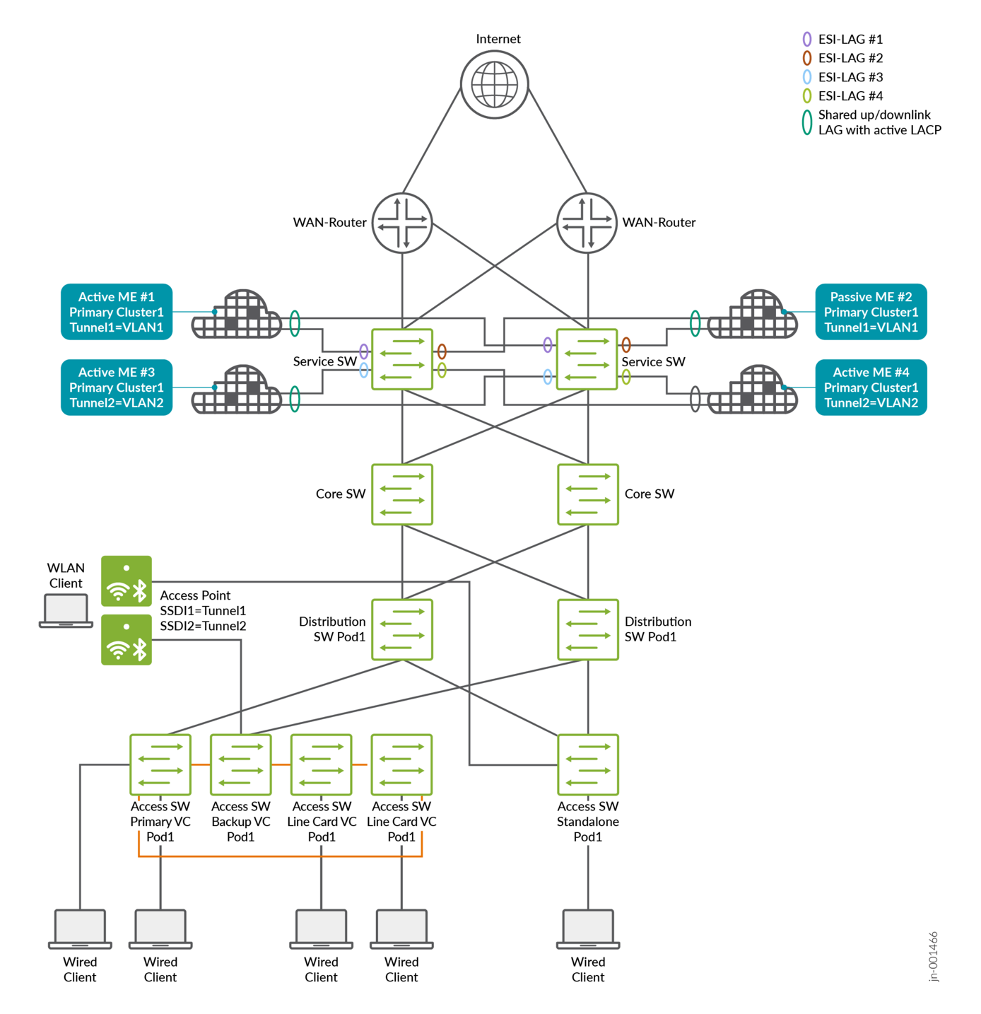
A mobility domain can be defined at its smallest level as a single VLAN within an SSID, where client traffic exits upstream into the fabric network. In the example in the last chapter, two client VLANs were multiplexed into one tunnel from the access point to a Juniper Mist Edge cluster with primary and secondary devices. In the updated design, two separate tunnels are used, with each VLAN mapped to one tunnel. This approach makes it possible to introduce a new pair of Juniper Mist Edges that only handle the traffic of the second tunnel and its associated VLAN. This change effectively splits the traffic load and provides the ability to scale by adding more Juniper Mist Edge pairs as needed.
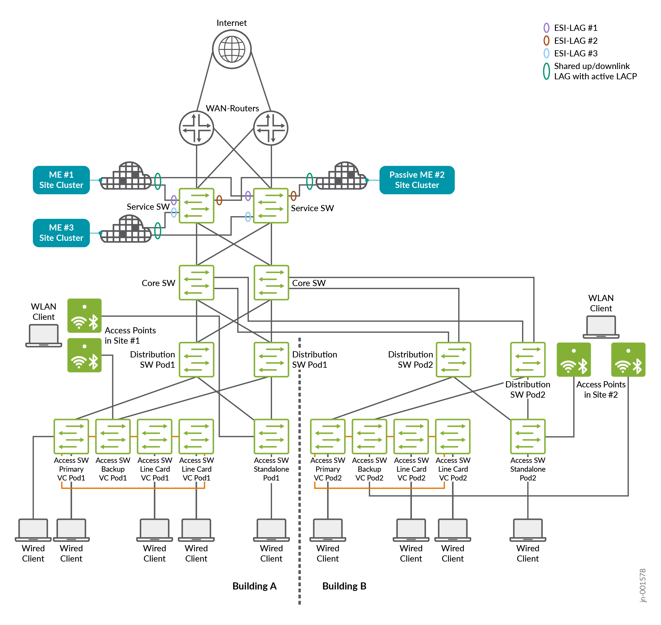
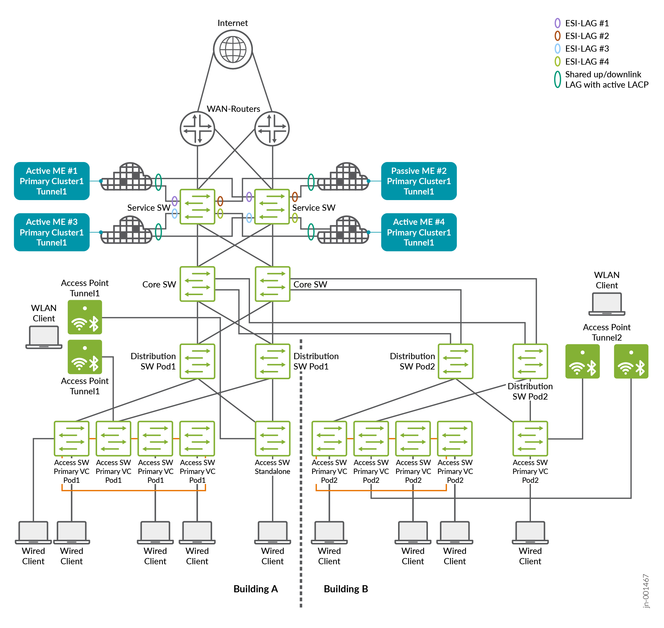
Another way to view mobility domains and their scalability is by considering the geographic location of wireless clients. For example, in a larger campus network using a PoD design (like that shown in the image below), a second set of distribution and access switches may be deployed for an additional building connected to the same fabric. In this scenario, we assume that for technical reasons the same wireless client VLANs must be supported across both PoDs simultaneously. However, clients are unlikely to roam, or will rarely roam, between the two buildings, with each PoD representing one building.
To increase scalability in this setup, the workload can be divided by assigning a dedicated pair of Juniper Mist Edges to each PoD, allowing them to scale independently. This is accomplished by creating two tunnels that each carry all VLANs. Access points in each PoD are then configured to use only the tunnel associated with their respective PoD, which is tied to the Juniper Mist Edge cluster serving that location.
There are many other ways to define how the Juniper Mist Edge cluster resources are used and how one can segment the traffic to accommodate higher scale. We cannot list all of them here as they change individually for each customers’ network requirements.
A single mobility domain implemented by a pair of redundant Juniper Mist Edges shall not exceed 4,000 connected APs.
The lab example seen below shows the more common approach in distributing VLANs across pairs of Juniper Mist Edge clusters.
Lab Preparation
In our lab we added the two additional Juniper Mist Edge switches as shown below:
Juniper Mist Edge and Fabric Configuration
We repeat the exact same configuration for fabric, service blocks, Juniper Mist Edges, APs and access switch as in the previous Building a Hybrid Lab with Two Juniper Mist Edges and ESI-LAG Fabric Attach. The changes needed are:
- Add ESI-LAGs on the service-block function
- Add two Juniper Mist Edge clusters
- Add one more tunnel
- Change the cluster and tunnel for split mobility support
- Optional: Change the AP site assignment for split mobility support
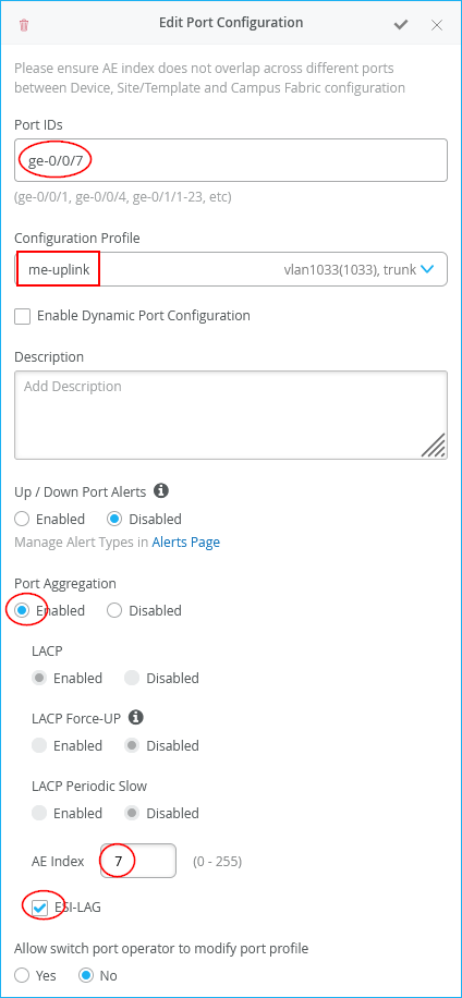
The configuration of Core1-Switch and Core2-Switch for the third Juniper Mist Edge is:
- Port ID=
ge-0/0/7 - Interface=
L2 interface - Configuration Profile=
me-uplink - Port Aggregation=
Enabled- AE Index=
7(you need to ensure this index value is unique and only used on the interface towards the same Juniper Mist Edge) - ESI-LAG=
Enabled(enabling this is mandatory)
- AE Index=
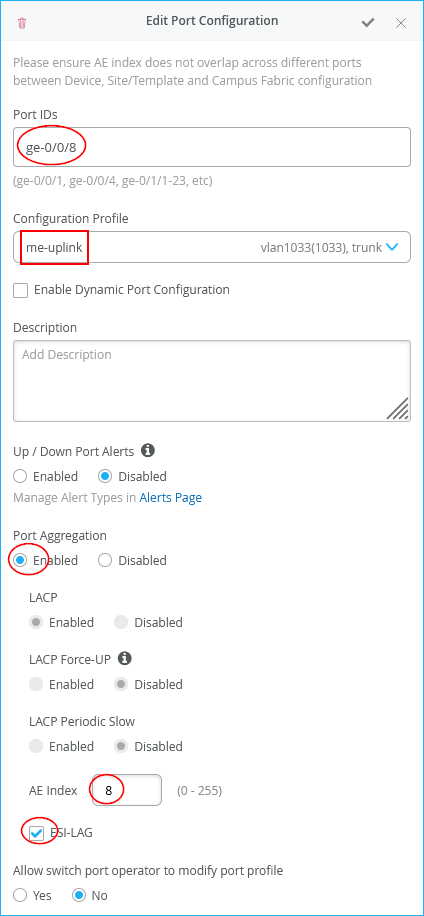
The configuration of Core1-Switch and Core2-Switch for the fourth Juniper Mist Edge is:
- Port ID=
ge-0/0/8 - Interface=
L2 interface - Configuration Profile=
me-uplink - Port Aggregation=
Enabled- AE Index=
8(you need to ensure this index value is unique and only used on the interface towards the same Juniper Mist Edge) - ESI-LAG=Enabled (enabling this is mandatory)
- AE Index=
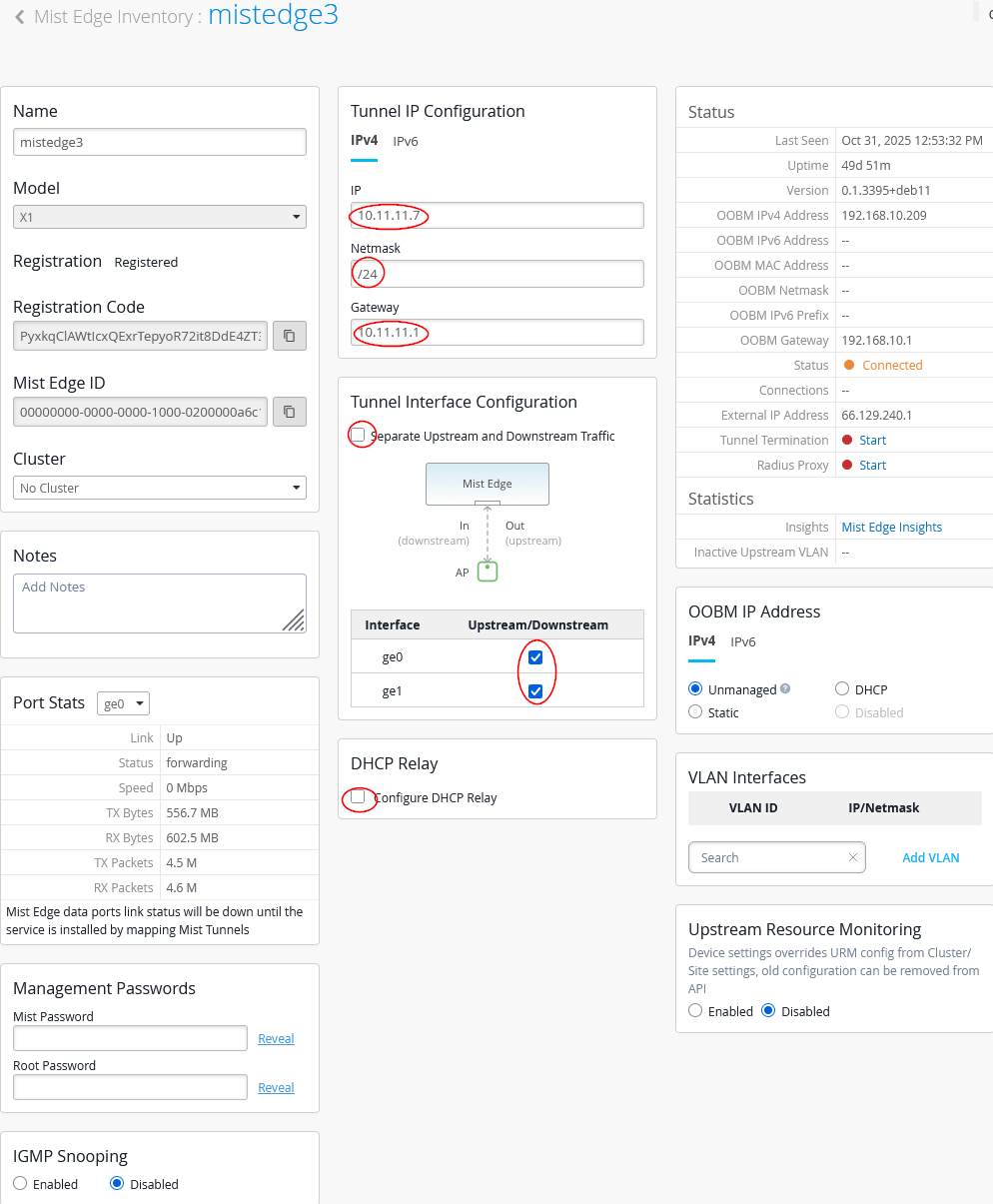
Next, we configure the third Juniper Mist Edge as follows:
- Name=
mistedge3 - IP=
10.11.11.7(remember the AP VLAN should be different from the VLAN used for Juniper Mist Edges) (remember our APs are in the same VLAN1033 but their DHCP lease range starts at 10.33.33.10) - Netmask=
/24 - Gateway=
10.11.11.1 - Separate Upstream and Downstream
Traffic=
Unchecked - Interface ge0=
Checked - Interface ge1=
Checked - DHCP Relay=
Unchecked
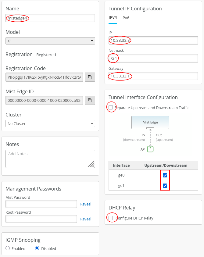
Next, we configure the fourth Juniper Mist Edge as follows:
- Name=
mistedge4 - IP=
10.11.11.8(remember the AP VLAN should be different from the VLAN used for Juniper Mist Edges) (remember our APs are in the same VLAN1033 but their DHCP lease range starts at 10.33.33.10) - Netmask=
/24 - Gateway=
10.11.11.1 - Separate Upstream and Downstream
Traffic=
Unchecked - Interface ge0=
Checked - Interface ge1=
Checked - DHCP Relay=
Unchecked
If you still have the configuration from the previous lab, first remove the tunnel assignments from the APs. Next, delete the tunnels themselves, followed by the site cluster configuration. Do not modify the existing Juniper Mist Edges, as their configurations can be reused without changes.
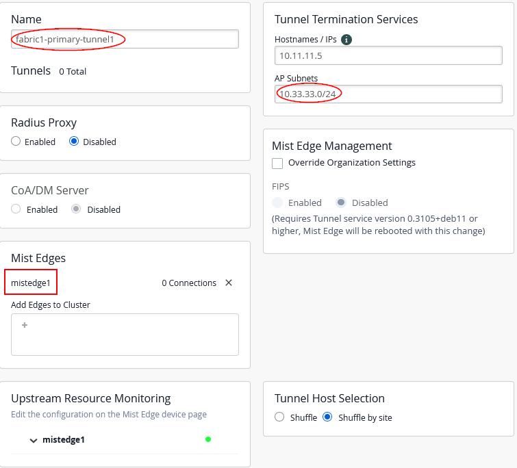
For the first Mist Edge cluster, configure the following:
- Name=
fabric1-primary-tunnel1 - Mist Edges=
mistedge1 - Hostnames / IPs=
10.11.11.5(happens automatically when assigning Mist Edge) - AP Subnets=
10.33.33.0/24(This is an optional configuration. With it enabled, the Juniper Mist Edge will only accept tunnels if the AP’s source IP address falls within the range assigned to VLAN 1033) - Tunnel Host Selection=
Shuffle by Site(This setting is required to configure all APs within the same site (fabric) to use the same Mist Edge)
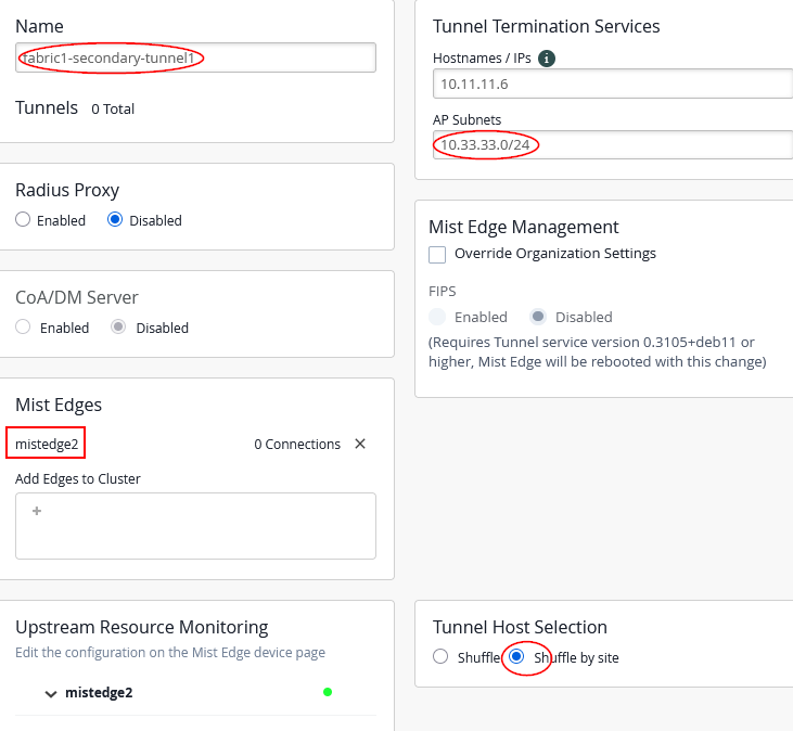
For the second Mist-Edge cluster configure:
- Name=
fabric1-secondary-tunnel1 - Mist Edges=
mistedge2 - Hostnames / IPs=
10.11.11.6(happens automatic when assigning Mist Edge) - AP Subnets=
10.33.33.0/24this is an OPTIONAL configuration and Mist-Edge would then only accept Tunnels when the Source IP-Address of the AP is in range on vlan1033. - Tunnel Host Selection=
Shuffle by SiteMANDATORY to tell all AP’s in same site (fabric) use the same Mist-Edge.
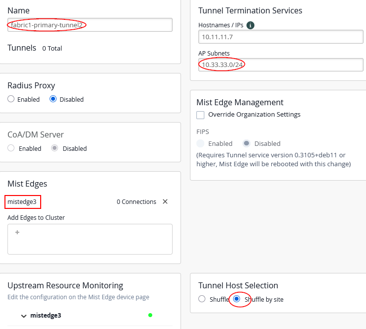
For the third Juniper Mist Edge cluster configure the following:
- Name=
fabric1-primary-tunnel2 - Mist Edges=
mistedge3 - Hostnames / IPs=
10.11.11.7(happens automatically when assigning the Juniper Mist Edge) - AP Subnets=
10.33.33.0/24(This configuration is optional. With it enabled, the Juniper Mist Edge will only accept tunnels if the AP’s source IP address falls within the range assigned to VLAN 1033) - Tunnel Host Selection=
Shuffle by Site(This configuration is required and ensures that all APs within the same site or fabric use the same Juniper Mist Edge)
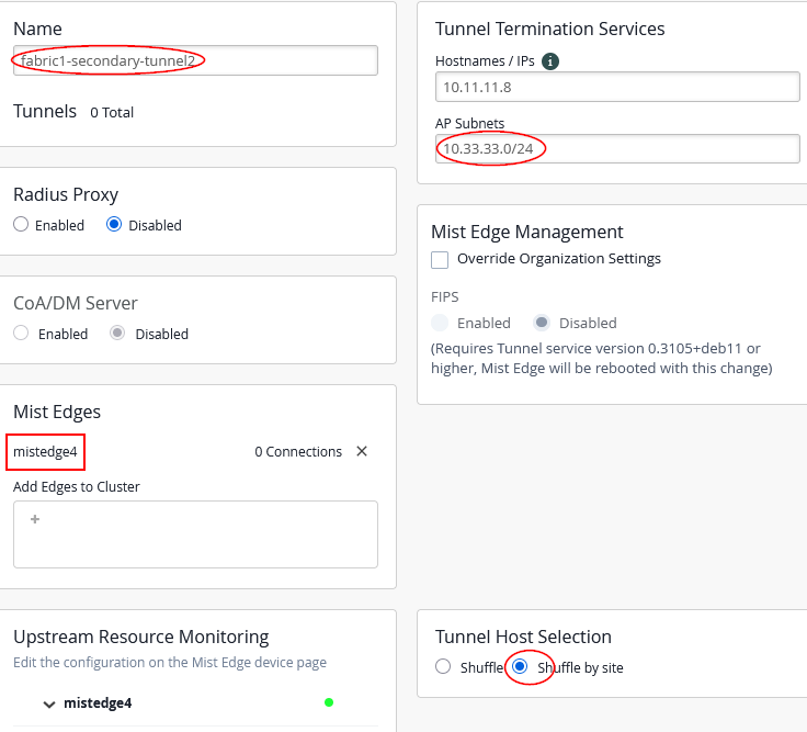
For the fourth Juniper Mist Edge cluster configure the following:
- Name=
fabric1-secondary-tunnel2 - Mist Edges=
mistedge4 - Hostnames / IPs=
10.11.11.8(happens automatically when assigning the Juniper Mist Edge) - AP Subnets=
10.33.33.0/24(This configuration is optional. With it enabled, the Juniper Mist Edge will only accept tunnels if the AP’s source IP address falls within the range assigned to VLAN 1033) - Tunnel Host Selection=
Shuffle by Site(This configuration is required and ensures that all APs within the same site or fabric use the same Juniper Mist Edge)
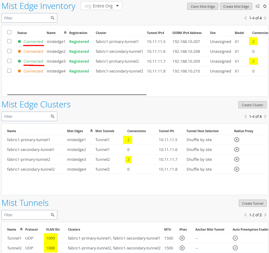
After making your changes, the configuration should look like the image shown below:
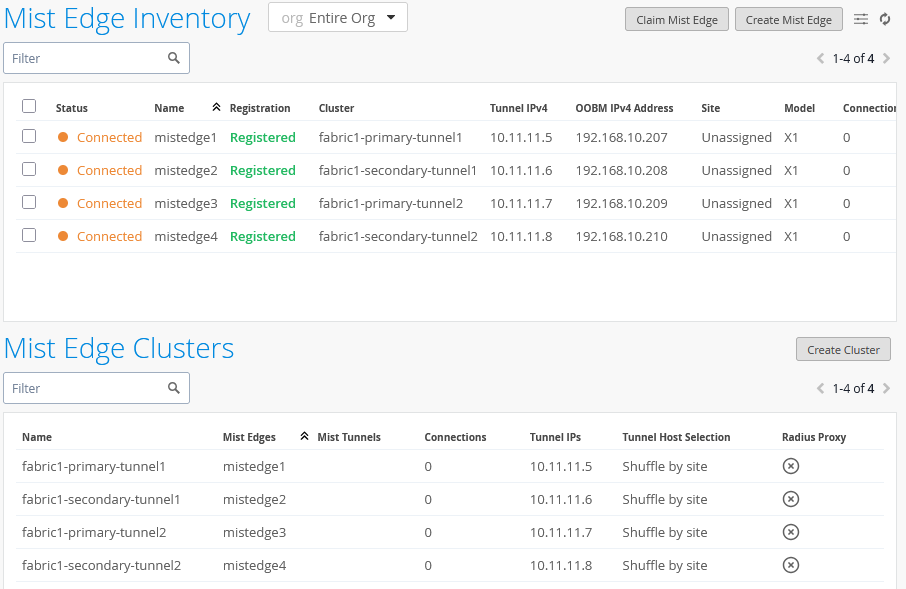
We are keeping the shuffle-by-site option here even if it is technically not a hard requirement as we have always only one Mist Edge per primary/secondary cluster. Using the shuffle-by-site option should be always used in all EVPN Fabric designs as good practice.
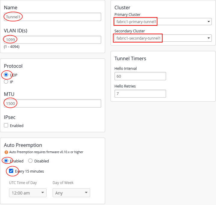
Create the first Overlay-Tunnel from Access Point to Mist-Edge (in our case in vlan1033) configuration:
- Name=
Tunnel1 - VLAN ID=
1099 - Primary Cluster=
fabric1-primary-tunnel1 - Secondary Cluster=
fabric1-secondary-tunnel1 - Protocol=
UDP - MTU=
1500 - IPsec=
Unchecked - Auto Preemption=
Enabled(If an AP accidentally roams to the second Juniper Mist Edge while the primary Edge is still active and managing the other APs, the AP will automatically roam back to the primary)- Every 15 minutes=
Checked(roaming back should happen as fast as possible, hence this configuration)
- Every 15 minutes=
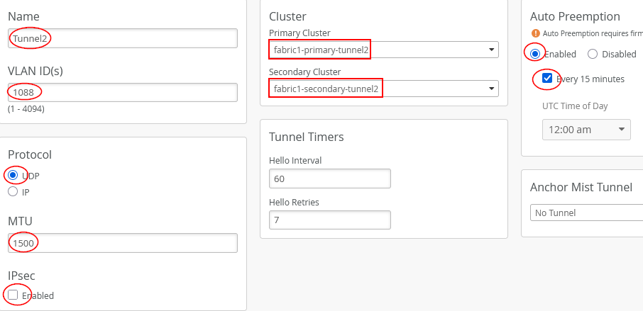
Next, add the configuration for the second overlay tunnel from AP to Juniper Mist Edge (in our case, in vlan1033):
- Name=
Tunnel2 - VLAN ID=
1088 - Primary Cluster=
fabric1-primary-tunnel2 - Secondary Cluster=
fabric1-secondary-tunnel2 - Protocol=
UDP - MTU=
1500 - IPsec=
Unchecked - Auto Preemption=
Enabled(If an AP accidentally roams to the second Juniper Mist Edge while the primary Edge is still active and managing the other APs, the AP will automatically roam back to the primary)- Every 15 minutes=
Checked(roaming back should happen as fast as possible, hence this configuration)
- Every 15 minutes=
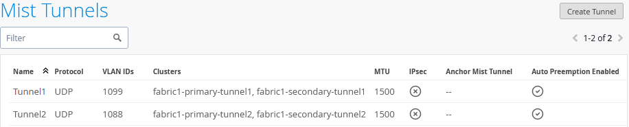
Your changes should look like the image shown below:
Check the configuration of the first SSID:
As we used VLAN 1099 for Tunnel1 and need to create the Custom Forwarding now configuring:
- Custom Forwarding=
Checked/Enabled- To=
Org Mist Edge
- To=
- Tunnel=
Tunnel1
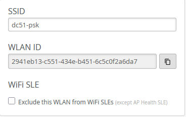
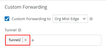
Check the configuration of the second SSID:
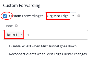
As we used VLAN 1088 for Tunnel2 and need to create the Custom Forwarding now configuring:
- Custom Forwarding=
Checked/Enabled- To=
Org Mist Edge
- To=
- Tunnel=
Tunnel2
After making this adjustment, each AP, with both SSIDs configured, will establish two tunnels to the designated primary cluster as shown below: