APPENDIX: Junos OS Configuration from This Fabric
Campus Fabric EVPN Multihoming Configurations
This section displays the configuration output from the Juniper Mist cloud for the IP Fabric underlay on the core and distribution switches using eBGP.
Juniper Mist provides the following options (default in parentheses):
- BGP Local AS (65000)
- AS Base (65001)
- Loopback pool (172.16.254.0/23)
- Subnet (10.255.240.0/20) – point-to-point interfaces between adjacent layers
Throughout the campus fabric between core and distribution layers, Juniper Mist enables per-packet (Junos OS defines this as per-flow) load balancing using ECMP and fast convergence of BGP in the event of a link or node failure using BFD.
Core1 Configuration:
- Interconnects with core2:
set interfaces et-0/0/48 description evpn_downlink-to-b033a6114900
set interfaces et-0/0/48 unit 0 family inet address 10.255.240.4/31
set interfaces et-0/0/49 description evpn_uplink-to-b033a6114900
set interfaces et-0/0/49 unit 0 family inet address 10.255.240.3/31
- Loopback interface and router ID:
set groups top interfaces lo0 unit 0 family inet address 172.16.254.2/32
set groups top routing-options router-id 172.16.254.2
- Per-packet load-balancing:
set groups top policy-options policy-statement ecmp_policy then load-balance per-packet
set groups top policy-options policy-statement ecmp_policy then accept
set groups top routing-options forwarding-table export ecmp_policy
- BGP underlay network between the two distribution switches:
set protocols bgp group evpn_underlay type external
set protocols bgp group evpn_underlay log-updown
set protocols bgp group evpn_underlay import evpn_underlay_import
set protocols bgp group evpn_underlay family inet unicast
set protocols bgp group evpn_underlay authentication-key "xyz"
set protocols bgp group evpn_underlay export evpn_underlay_export
set protocols bgp group evpn_underlay local-as 65002
set protocols bgp group evpn_underlay multipath multiple-as
set protocols bgp group evpn_underlay bfd-liveness-detection minimum- interval 350
set protocols bgp group evpn_underlay bfd-liveness-detection multiplier 3
set protocols bgp group evpn_underlay neighbor 10.255.240.2 peer-as 65001
set protocols bgp group evpn_underlay neighbor 10.255.240.5 peer-as 65001
Core2 Configuration:
- Interconnects between the two distribution switches:
set interfaces et-0/0/48 description evpn_uplink-to-c042d016afa0
set interfaces et-0/0/48 unit 0 family inet address 10.255.240.5/31
set interfaces et-0/0/49 description evpn_downlink-to-c042d016afa0
set interfaces et-0/0/49 unit 0 family inet address 10.255.240.2/31
- Loopback interface and router ID:
set groups top interfaces lo0 unit 0 family inet address 172.16.254.1/32
set groups top routing-options router-id 172.16.254.1
- Per-packet load balancing:
set groups top policy-options policy-statement ecmp_policy then load-balance per-packet
set groups top policy-options policy-statement ecmp_policy then accept
set groups top routing-options forwarding-table export ecmp_policy
- BGP underlay network between the two distribution switches:
set protocols bgp group evpn_underlay type external
set protocols bgp group evpn_underlay type external
set protocols bgp group evpn_underlay log-updown
set protocols bgp group evpn_underlay import evpn_underlay_import
set protocols bgp group evpn_underlay family inet unicast
set protocols bgp group evpn_underlay authentication-key "xyz"
set protocols bgp group evpn_underlay export evpn_underlay_export
set protocols bgp group evpn_underlay local-as 65001
set protocols bgp group evpn_underlay multipath multiple-as
set protocols bgp group evpn_underlay bfd-liveness-detection minimum- interval 350
set protocols bgp group evpn_underlay bfd-liveness-detection multiplier 3
set protocols bgp group evpn_underlay neighbor 10.255.240.4 peer-as 65002
set protocols bgp group evpn_underlay neighbor 10.255.240.3 peer-as 65002
Configuration of the EVPN-VXLAN Overlay and Virtual Networks
This section displays the Juniper Mist cloud configuration output for the EVPN-VXLAN overlay on the core and distribution switches using eBGP.
Juniper Mist enables load balancing across the overlay network and fast convergence of BGP in the event of a link or node failure using BFD between the core and distribution layers.
Juniper Mist provisions Layer 3 IRB interfaces on the distribution layer.
Juniper Mist enables VXLAN tunnelling, VLAN to VXLAN mapping, and MP-BGP configuration snippets such as vrf-targets on the distribution and core switches.
The VRFs for traffic isolation are provisioned on the distribution switches.
Core1 Configuration:
- BGP overlay peering between the two distribution switches:
set protocols bgp group evpn_overlay type internal
set protocols bgp group evpn_overlay local-address 172.16.254.2
set protocols bgp group evpn_overlay log-updown
set protocols bgp group evpn_overlay family evpn signaling
set protocols bgp group evpn_overlay authentication-key "xyz"
set protocols bgp group evpn_overlay cluster 1.0.0.1
set protocols bgp group evpn_overlay local-as 65000
set protocols bgp group evpn_overlay multipath
set protocols bgp group evpn_overlay bfd-liveness-detection minimum- interval 1000
set protocols bgp group evpn_overlay bfd-liveness-detection multiplier 3
set protocols bgp group evpn_overlay bfd-liveness-detection session-mode automatic
set protocols bgp group evpn_overlay neighbor 172.16.254.1
- Switch options that define vrf-targets and the source loopback
interface used for VXLAN:
set groups top switch-options vtep-source-interface lo0.0
set groups top switch-options route-distinguisher 172.16.254.2:1
set groups top switch-options vrf-target target:65000:1
set groups top switch-options vrf-target auto
- VXLAN encapsulation:
set groups top protocols evpn no-core-isolation
set groups top protocols evpn encapsulation vxlan
set groups top protocols evpn default-gateway no-gateway-community
set groups top protocols evpn extended-vni-list all
- VRFs used for traffic isolation:
set groups top routing-instances guest-wifi instance-type vrf
set groups top routing-instances guest-wifi routing-options static route 0.0.0.0/0 next-hop 10.33.33.254
set groups top routing-instances guest-wifi routing-options auto-export
set groups top routing-instances guest-wifi interface irb.1033
set groups top routing-instances guest-wifi route-distinguisher 172.16.254.2:103
set groups top routing-instances guest-wifi vrf-target target:65000:103
set groups top routing-instances guest-wifi vrf-table-label
set groups top routing-instances developers instance-type vrf
set groups top routing-instances developers routing-options static route 0.0.0.0/0 next-hop 10.88.88.254
set groups top routing-instances developers routing-options auto-export
set groups top routing-instances developers interface irb.1088
set groups top routing-instances developers route-distinguisher 172.16.254.2:102
set groups top routing-instances developers vrf-target target:65000:102
set groups top routing-instances developers vrf-table-label
set groups top routing-instances corp-it instance-type vrf
set groups top routing-instances corp-it routing-options static route 0.0.0.0/0 next-hop 10.99.99.254
set groups top routing-instances corp-it routing-options auto-export
set groups top routing-instances corp-it interface irb.1099
set groups top routing-instances corp-it route-distinguisher 172.16.254.2:101
set groups top routing-instances corp-it vrf-target target:65000:101
set groups top routing-instances corp-it vrf-table-label
- VLAN to VXLAN mapping:
set vlans vlan1033 vlan-id 1033
set vlans vlan1033 l3-interface irb.1033
set vlans vlan1033 vxlan vni 11033
set vlans vlan1088 vlan-id 1088
set vlans vlan1088 l3-interface irb.1088
set vlans vlan1088 vxlan vni 11088
set vlans vlan1099 vlan-id 1099
set vlans vlan1099 l3-interface irb.1099
set vlans vlan1099 vxlan vni 11099
- Layer 3 IRB interface enablement with virtual gateway
addressing:
set interfaces irb unit 1033 virtual-gateway-accept-data
set interfaces irb unit 1033 description vlan1033
set interfaces irb unit 1033 family inet address 10.33.33.2/24 virtual-gateway-address 10.33.33.1
set interfaces irb unit 1088 virtual-gateway-accept-data
set interfaces irb unit 1088 description vlan1088
set interfaces irb unit 1088 family inet address 10.88.88.2/24 virtual-gateway-address 10.88.88.1
set interfaces irb unit 1099 virtual-gateway-accept-data
set interfaces irb unit 1099 description vlan1099
set interfaces irb unit 1099 family inet address 10.99.99.2/24 virtual-gateway-address 10.99.99.1
Core2 Configuration:
- BGP overlay peering between the two distribution switches:
set protocols bgp group evpn_overlay type internal
set protocols bgp group evpn_overlay local-address 172.16.254.1
set protocols bgp group evpn_overlay log-updown
set protocols bgp group evpn_overlay family evpn signaling
set protocols bgp group evpn_overlay authentication-key "xyz"
set protocols bgp group evpn_overlay cluster 1.0.0.1
set protocols bgp group evpn_overlay local-as 65000
set protocols bgp group evpn_overlay multipath
set protocols bgp group evpn_overlay bfd-liveness-detection minimum- interval 1000
set protocols bgp group evpn_overlay bfd-liveness-detection multiplier 3
set protocols bgp group evpn_overlay bfd-liveness-detection session-mode automatic
set protocols bgp group evpn_overlay neighbor 172.16.254.2
- Switch options that define vrf-targets and the source loopback
interface used for VXLAN:
set groups top switch-options vtep-source-interface lo0.0
set groups top switch-options route-distinguisher 172.16.254.1:1
set groups top switch-options vrf-target target:65000:1
set groups top switch-options vrf-target auto
- VXLAN encapsulation:
set groups top protocols evpn no-core-isolation
set groups top protocols evpn encapsulation vxlan
set groups top protocols evpn default-gateway no-gateway-community
set groups top protocols evpn extended-vni-list all
- VRFs used for traffic isolation:
set groups top routing-instances guest-wifi instance-type vrf
set groups top routing-instances guest-wifi routing-options static route 0.0.0.0/0 next-hop 10.33.33.254
set groups top routing-instances guest-wifi routing-options auto-export
set groups top routing-instances guest-wifi interface irb.1033
set groups top routing-instances guest-wifi route-distinguisher 172.16.254.1:103
set groups top routing-instances guest-wifi vrf-target target:65000:103
set groups top routing-instances guest-wifi vrf-table-label
set groups top routing-instances developers instance-type vrf
set groups top routing-instances developers routing-options static route 0.0.0.0/0 next-hop 10.88.88.254
set groups top routing-instances developers routing-options auto-export
set groups top routing-instances developers interface irb.1088
set groups top routing-instances developers route-distinguisher 172.16.254.1:102
set groups top routing-instances developers vrf-target target:65000:102
set groups top routing-instances developers vrf-table-label
set groups top routing-instances corp-it instance-type vrf
set groups top routing-instances corp-it routing-options static route 0.0.0.0/0 next-hop 10.99.99.254
set groups top routing-instances corp-it routing-options auto-export
set groups top routing-instances corp-it interface irb.1099
set groups top routing-instances corp-it route-distinguisher 172.16.254.1:101
set groups top routing-instances corp-it vrf-target target:65000:101
set groups top routing-instances corp-it vrf-table-label
- VLAN to VXLAN mapping:
set vlans vlan1033 vlan-id 1033
set vlans vlan1033 l3-interface irb.1033
set vlans vlan1033 vxlan vni 11033
set vlans vlan1088 vlan-id 1088
set vlans vlan1088 l3-interface irb.1088
set vlans vlan1088 vxlan vni 11088
set vlans vlan1099 vlan-id 1099
set vlans vlan1099 l3-interface irb.1099
set vlans vlan1099 vxlan vni 11099
- Layer 3 IRB interface enablement with virtual gateway
addressing.
set interfaces irb unit 1033 virtual-gateway-accept-data
set interfaces irb unit 1033 description vlan1033
set interfaces irb unit 1033 family inet address 10.33.33.3/24 virtual-gateway-address 10.33.33.1
set interfaces irb unit 1088 virtual-gateway-accept-data
set interfaces irb unit 1088 description vlan1088
set interfaces irb unit 1088 family inet address 10.88.88.3/24 virtual-gateway-address 10.88.88.1
set interfaces irb unit 1099 virtual-gateway-accept-data
set interfaces irb unit 1099 description vlan1099
set interfaces irb unit 1099 family inet address 10.99.99.3/24 virtual-gateway-address 10.99.99.1
Configuration of the Layer 2 ESI-LAG Between the Distribution Switches and the Access Switches
This section displays the configuration output from the Juniper Mist cloud for the enablement of the Layer 2 ESI-LAGs between the distribution switches and access switches. This Juniper Mist profile enables all VLANs on the Ethernet bundle with requisite ESI and LACP configuration options. From the perspective of the access switches, the Ethernet bundle that is configured on the access layer views the ESI-LAG as a single MAC address with the same LACP system-ID. This enables load hashing between distribution and access layers without requiring Layer 2 loop-free detection protocols such as RSTP.
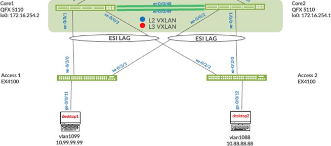
Core1 Configuration:
- Interface association with the newly created Ethernet bundle
that includes ESI and LACP configuration:
set interfaces ae0 apply-groups esi-lag
set interfaces ae0 esi 00:11:00:00:00:01:00:01:02:00 set interfaces ae0 esi all-active
set interfaces ae0 aggregated-ether-options lacp active
set interfaces ae0 aggregated-ether-options lacp periodic fast set interfaces ae0 aggregated-ether-options lacp system-id 00:00:00:31:57:00
set interfaces ae0 aggregated-ether-options lacp admin-key 0
set interfaces ae1 apply-groups esi-lag
set interfaces ae1 esi 00:11:00:00:00:01:00:01:02:01 set interfaces ae1 esi all-active
set interfaces ae1 aggregated-ether-options lacp active
set interfaces ae1 aggregated-ether-options lacp periodic fast set interfaces ae1 aggregated-ether-options lacp system-id 00:00:00:31:57:01
set interfaces ae1 aggregated-ether-options lacp admin-key 1
set groups esi-lag interfaces <*> unit 0 family ethernet-switching interface-mode trunk
set groups esi-lag interfaces <*> unit 0 family ethernet-switching vlan members vlan1033
set groups esi-lag interfaces <*> unit 0 family ethernet-switching vlan members vlan1088
set groups esi-lag interfaces <*> unit 0 family ethernet-switching vlan members vlan1099
set interfaces xe-0/0/1 description esilag-to-4c734f095900 set interfaces xe-0/0/1 hold-time up 120000
set interfaces xe-0/0/1 hold-time down 1
set interfaces xe-0/0/1 ether-options 802.3ad ae1
set interfaces xe-0/0/1 unit 0 family ethernet-switching storm-control default
deactivate interfaces xe-0/0/1 unit 0
set interfaces xe-0/0/2 description esilag-to-4c734f095900 set interfaces xe-0/0/2 hold-time up 120000
set interfaces xe-0/0/2 hold-time down 1
set interfaces xe-0/0/2 ether-options 802.3ad ae0
Core2 Configuration:
- Interface association with the newly created Ethernet bundle
that includes ESI and LACP configuration:
set interfaces ae0 apply-groups esi-lag
set interfaces ae0 esi 00:11:00:00:00:01:00:01:02:00 set interfaces ae0 esi all-active
set interfaces ae0 aggregated-ether-options lacp active
set interfaces ae0 aggregated-ether-options lacp periodic fast
set interfaces ae0 aggregated-ether-options lacp system-id 00:00:00:31:57:00
set interfaces ae0 aggregated-ether-options lacp admin-key 0
set interfaces ae1 apply-groups esi-lag
set interfaces ae1 esi 00:11:00:00:00:01:00:01:02:01 set interfaces ae1 esi all-active
set interfaces ae1 aggregated-ether-options lacp active
set interfaces ae1 aggregated-ether-options lacp periodic fast
set interfaces ae1 aggregated-ether-options lacp system-id 00:00:00:31:57:01
set interfaces ae1 aggregated-ether-options lacp admin-key 1
set groups esi-lag interfaces <*> unit 0 family ethernet-switching interface-mode trunk
set groups esi-lag interfaces <*> unit 0 family ethernet-switching vlan members vlan1033
set groups esi-lag interfaces <*> unit 0 family ethernet-switching vlan members vlan1088
set groups esi-lag interfaces <*> unit 0 family ethernet-switching vlan members vlan1099
set interfaces xe-0/0/1 description esilag-to-4c734f095900
set interfaces xe-0/0/1 hold-time up 120000
set interfaces xe-0/0/1 hold-time down 1
set interfaces xe-0/0/1 ether-options 802.3ad ae1
set interfaces xe-0/0/1 unit 0 family ethernet-switching storm-control default
deactivate interfaces xe-0/0/1 unit 0
set interfaces xe-0/0/2 description esilag-to-4c734f095900
set interfaces xe-0/0/2 hold-time up 120000
set interfaces xe-0/0/2 hold-time down 1
set interfaces xe-0/0/2 ether-options 802.3ad ae0
set interfaces xe-0/0/2 unit 0 family ethernet-switching storm-control default
deactivate interfaces xe-0/0/2 unit 0
Access1 Configuration:
- VLANs associated with the new LACP Ethernet bundle:
set groups esi-lag interfaces <*> mtu 9200
set groups esi-lag interfaces <*> unit 0 family ethernet-switching interface-mode trunk
set groups esi-lag interfaces <*> unit 0 family ethernet-switching vlan members vlan1033
set groups esi-lag interfaces <*> unit 0 family ethernet-switching vlan members vlan1088
set groups esi-lag interfaces <*> unit 0 family ethernet-switching vlan members vlan1099
set interfaces ae1 apply-groups esi-lag
set interfaces ae1 aggregated-ether-options lacp active
set interfaces xe-0/2/0 ether-options 802.3ad ae1
set interfaces xe-0/2/0 unit 0 family ethernet-switching storm-control default
deactivate interfaces xe-0/2/0 unit 0
set interfaces xe-0/2/3 ether-options 802.3ad ae1
set interfaces xe-0/2/3 unit 0 family ethernet-switching storm-control default
deactivate interfaces xe-0/2/3 unit 0
Access2 Configuration:
- VLANs associated with the new LACP Ethernet bundle:
set groups esi-lag interfaces <*> mtu 9200
set groups esi-lag interfaces <*> unit 0 family ethernet-switching interface-mode trunk
set groups esi-lag interfaces <*> unit 0 family ethernet-switching vlan members vlan1033
set groups esi-lag interfaces <*> unit 0 family ethernet-switching vlan members vlan1088
set groups esi-lag interfaces <*> unit 0 family ethernet-switching vlan members vlan1099
set interfaces ae0 apply-groups esi-lag
set interfaces ae0 aggregated-ether-options lacp active
set interfaces xe-0/2/0 ether-options 802.3ad ae0
set interfaces xe-0/2/0 unit 0 family ethernet-switching storm-control default
deactivate interfaces xe-0/2/0 unit 0
set interfaces xe-0/2/3 ether-options 802.3ad ae0
set interfaces xe-0/2/3 unit 0 family ethernet-switching storm-control default
deactivate interfaces xe-0/2/3 unit 0
Configuration of the Layer 2 ESI-LAG Between the Core Switches and the MX Router
This section displays the configuration output from the Juniper Mist cloud for the enablement of the Layer 2 ESI LAG between the core switches and SRX Series Firewall. This Mist profile enables all VLANs on the Ethernet bundle with requisite ESI and LACP configuration options. From the perspective of the SRX Series Firewall, the Ethernet bundle that is configured on the SRX Series Firewall views the ESI-LAG as a single MAC address with the same LACP system- ID. This enables load hashing between the core and SRX Series Firewall without requiring Layer 2 loop-free detection protocols such as RSTP.
.png)
Core 1 Configuration:
- Interface association with the newly created Ethernet bundle
that includes ESI and LACP configuration:
set interfaces ge-0/0/10 description esilag-to-4c734f095900
set interfaces ge-0/0/10 hold-time up 120000
set interfaces ge-0/0/10 hold-time down 1
set interfaces ge-0/0/10 ether-options 802.3ad ae2
set interfaces ge-0/0/10 unit 0 family ethernet-switching storm-control default
deactivate interfaces ge-0/0/10 unit 0
set interfaces ae2 apply-groups esi-lag
set interfaces ae2 esi 00:11:00:00:00:01:00:01:02:02
set interfaces ae2 esi all-active
set interfaces ae2 aggregated-ether-options lacp active
set interfaces ae2 aggregated-ether-options lacp periodic fast
set interfaces ae2 aggregated-ether-options lacp system-id 00:00:00:31:57:02
set interfaces ae2 aggregated-ether-options lacp admin-key 2
Core 2 Configuration:
- Interface association with the newly created Ethernet bundle
that includes ESI and LACP configuration:
set interfaces ge-0/0/10 description esilag-to-4c734f095900
set interfaces ge-0/0/10 hold-time up 120000
set interfaces ge-0/0/10 hold-time down 1
set interfaces ge-0/0/10 ether-options 802.3ad ae2
set interfaces ge-0/0/10 unit 0 family ethernet-switching storm-control default
deactivate interfaces ge-0/0/10 unit 0
set interfaces ae2 apply-groups esi-lag
set interfaces ae2 esi 00:11:00:00:00:01:00:01:02:02 set interfaces ae2 esi all-active
set interfaces ae2 aggregated-ether-options lacp active
set interfaces ae2 aggregated-ether-options lacp periodic fast
set interfaces ae2 aggregated-ether-options lacp system-id 00:00:00:31:57:02
set interfaces ae2 aggregated-ether-options lacp admin-key 2
SRX Series Firewall Configuration:
- Interface association with newly created Ethernet bundle and
LACP configuration:
set interfaces ae0 flexible-vlan-tagging
set interfaces ae0 aggregated-ether-options lacp active
set interfaces ae0 unit 1033 vlan-id 1033
set interfaces ae0 unit 1033 family inet address 10.33.33.254/24
set interfaces ae0 unit 1088 vlan-id 1088
set interfaces ae0 unit 1088 family inet address 10.88.88.254/24
set interfaces ae0 unit 1099 vlan-id 1099
set interfaces ae0 unit 1099 family inet address 10.99.99.254/24