Solution Architecture
Before mentioning the suggested production-grade architecture, for completion’s sake, we will share the approach to use if security is not a concern and faster results are preferred.
Proof of Concept Non-Production-Grade DHCP Server Integration Approach
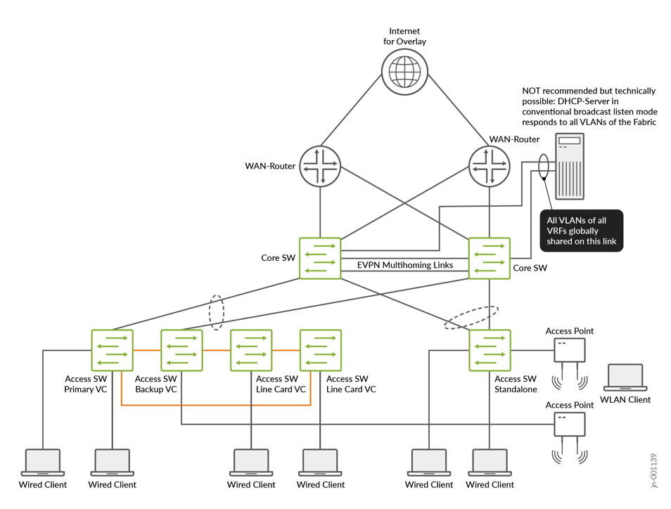
In this approach, the DHCP server is attached locally to the fabric’s service block function. For redundancy, an ESI-LAG is configured on the fabric side and a normal LAG on the server side. All possible 4,000+ VLANs are configured and exposed on this link towards the DHCP server. The fabric itself then needs no extra configuration of DHCP relay as the Layer 2 broadcast domains of all access VLANs are stretched to the DHCP server. By configuring matching sub-interfaces to listen on, the DHCP server can then assign leases by listening to the MAC broadcast packets the clients send. This works the old-fashioned way, and many DHCP servers (including Junos OS) can respond to this traffic.
This is clearly not recommended in production-grade designs and rollouts. It may help getting the network up faster, but there are severe security risks that come with such a design!
The reason for not recommending this in production-grade designs is that you bypass a basic security function of the fabric design. Normally, all fabric VRFs are isolated from each other. This forces all traffic between VLANs in different VRFs to transit the WAN router where security functions such as firewalls can be implemented. By placing all VLANs on the link to the DHCP server in the service block, we bypass the WAN router and thus the security functionality. If an attacker finds a security hole such as an open administrator login, or something is misconfigured, the attacker can jump between all VLANs and maybe also bypass any WAN router-based screening between VRFs. Please be aware of this trade-off.
Recommended Production-Grade DHCP Server Integration Approach
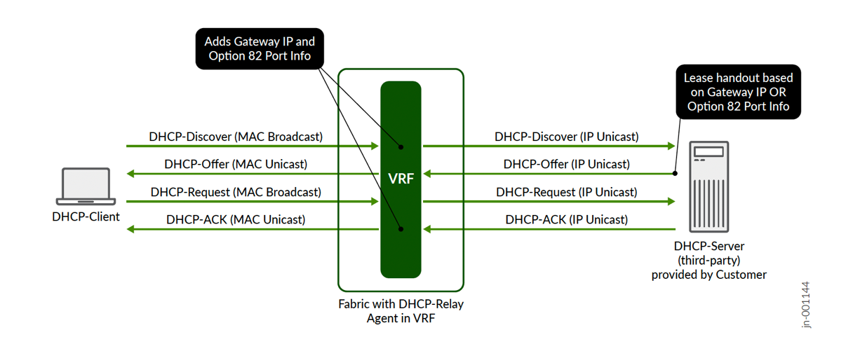
The recommended production-grade solution is to follow an IETF RFC 2131 and RFC 3046 standards-based approach leveraging DHCP relay inside the fabric to forward to a customer-managed DHCP server.
In a campus fabric, the DHCP relay is usually located where the Layer 3 gateway VRF sends traffic from the attached access switches towards the north-bound functions. This is because this is the demarcation between the Layer 2 broadcast domain and the remaining Layer 3 forwarding in the network. A DHCP client requesting a lease always addresses the broadcast MAC address in this Layer 2 domain, which is FF:FF:FF:FF:FF:FF. Once such a message reaches the VRF, it is forwarded by the VRF’s DHCP relay function (RFC 2131 calls this a BOOTP relay agent) as an IP UDP packet towards the DHCP server attached to the fabric or outside of it. Along with this, forwarding additional information is always embedded in the UDP packet towards the DHCP server:
- The Gateway IP (RFC 2131 calls this the “giaddr”)
is the source IP address of the DHCP packet. The DHCP servers send
all response packets back to this embedded IP address. Hence, it is
important that this IP address is reachable by the responding
packets. This reported source IP may differ depending on the fabric
type and the WAN router integration method. The two most popular
methods which are illustrated in this JVD are:
- For small fabrics using virtual gateway addressing, the static IP address for each overlay VLAN that is locally configured on each fabric VRF is used as the gateway IP.
- For larger fabrics where anycast addressing is in use, an
additional range of overlay loopback IPs is used by the VRFs
distributed across the fabric. Each VRF across all nodes where VRFs
are configured in this fabric gets a unique IP address used as the
gateway IP. Hence, you have an additional overlay network, but one
that is shared across VRFs. It needs to be noted that in this case
there are two flavours of loopback IP address usage:
- There are always the existing underlay loopback IP addresses bound to the lo0.0 interface on each EVPN fabric switch. These are used for VXLAN VTEP and EVPN BGP signalling. They are typically invisible for the overlay transport.
- The new loopback IP addresses used for DHCP relay are visible in the overlay VLANs. When defining this overlay loopback pool, take care that this range is not used elsewhere by the overlay VLANs. Also, the IP addresses in this overlay loopback pool must only be bound to nodes of the EVPN fabric where the VRFs are located.
- It’s expected that the DHCP relay function embeds additional information such as that added by DHCP option 82 according to RFC 3046. This helps the DHCP server to identify the source of the client request and to be able to better manage the lease handout decision. This is needed because the DHCP server will no longer be able to receive DHCP lease requests from local VLANs since it is configured to listen on an IP address socket-interface receiving UDP packets. The possible attributes that can be embedded in option 82 by the DHCP server vendor can vary and is always subject to integration with the fabric.
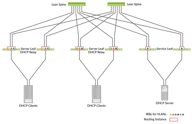
As already mentioned, the fabric configures the DHCP relay function where the VRFs are located in your fabric. Do not attempt to manually change this on the switches. Inside the fabric configuration fields, you will find DHCP relay configuration options in the pane where you configure the networks and VRFs. The rest will be deployed automatically by the Juniper Mist™ cloud on the necessary nodes as indicated in the figure below:
| Fabric Type | DHCP Relay will be Configured On | Number of Supported Nodes |
|---|---|---|
| EVPN Multihoming | Collapsed Core Switches | Maximum 4 |
| CRB | Core Switches | Maximum 4 |
| ERB | Distribution Switches | many |
| IP Clos Routed at Edge | Access Switches | many |
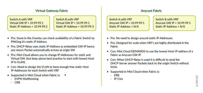
Virtual Gateway Fabric Versus Anycast Fabric
Depending on the fabric type, the overlay VLANs (where the client traffic is located), may need additional IP addresses for internal purposes, which is the case for virtual gateway fabrics. The Juniper Mist campus fabric configures the following fabric types:
| Fabric Type | Virtual Gateway Fabric | Anycast Fabric | |
|---|---|---|---|
| EVPN Multihoming | Yes | --- | |
| CRB | Yes | --- | |
| ERB | --- | Yes | |
| IP Clos Fabric | --- | Yes | |
In a virtual gateway fabric, you typically have a very limited amount of VRFs. Those are located on the core or collapsed core switches. The maximum amount of core or collapsed core switches supported in a Juniper Mist campus fabric is four. This means a certain VRF can be duplicated to each redundant core or collapsed core switch a maximum of four times in the fabric. Anycast fabrics, as opposed to virtual gateway fabrics, are appropriate for more scaled designs. Hence, the location of the VRFs is either on the distribution switches (ERB) or at the access switch (IP Clos fabric). The nature of virtual gateway fabrics is that the system requires an additional static IP address that is unique per VRF for every VLAN located in the fabric. Hence, in addition to the shared gateway IP address for each VLAN, up to four additional unique IP addresses on that subnet are required.
Why such a design? There are benefits for certain traffic on the fabric such as DHCP relay. For DHCP relay, the system uses the static IP address instead of the gateway IP address when forwarding the DHCP client requests. This behavior ensures that the DHCP response packet will be sent back to the correct VRF since the static IP address is unique to the VLAN/core switch.
Another way to think about a virtual gateway fabric is if you compare it with traditional Layer 2 gateway failover designs such as VRRP. There you always have a VIP which floats between the gateways (that are our VRFs) and each gateway needs an additional unique static IP for each VLAN. In a Juniper Mist campus fabric, the VRRP protocol is not needed as the EVPN control plane takes over for it.
The small sacrifice needed to carve out those additional static IP addresses in each subnet is eliminated in anycast fabrics. This is because of the more scaled distribution/access switches where VRFs are installed you would have to plan your future growth well when creating VLANs. System services such as DHCP relay work in anycast fabrics a bit differently and are internally more complex.
Which IP Address to Choose as Reported Gateway IP Address?
You must typically choose between one of the following approaches to determine which gateway IP address is embedded in the packets forwarded by the DHCP relay function in the fabric:
- For EVPN multihoming fabrics, the UI does not provide any choice so you will always be using virtual gateway IP addresses for the gateway IP. This enables the DHCP server to identify the VLAN where the request originates by only analyzing the gateway IP address embedded in the forwarded packets.
- For CRB fabrics, you can select between virtual gateway static IP address design by leaving the field “Loopback per-VRF subnet” empty or by using a design with overlay loopback IP addresses assigned to each VRF in the fabric when populating an IP prefix in the “Loopback per-VRF subnet” of the campus fabric dialogue.
- For larger fabrics such as ERB and IP Clos, we recommend entering an IP prefix in the “Loopback per-VRF subnet” as part of the campus fabric configuration. By doing so, the fabric will automatically assign unique overlay loopback IPs out of this pool range to each VRF in the fabric. In this case, we also highly recommend leveraging a routing protocol such as OSPF or BGP for WAN router integration towards the fabric as the usage of these overlay loopback IPs can make it difficult to predict how each gateway IP can be reached from the WAN router.
While it is technically possible to leave the "Loopback per-VRF subnet" field empty in these fabrics, it is not recommended. If left blank, the anycast gateway IP will be the reported gateway IP embedded in the forwarded packets. This doesn’t cause issues on the way to the DHCP server. However, when the DHCP server's response returns, because the anycast IP is shared by multiple switches within the fabric, the response packet might be routed to a switch that did not originate the request and could be in a different PoD or building. If this happens, when the packet arrives at a switch that didn’t initiate the request, the DHCP relay function will decapsulate the response and determine, based on the client's MAC address, that the packet must be forwarded to a remote switch. To do so, it will use a VXLAN tunnel to resend the packet east-west to the switch where the client is actually connected. This creates an inefficient design.
Where to Locate the DHCP Server
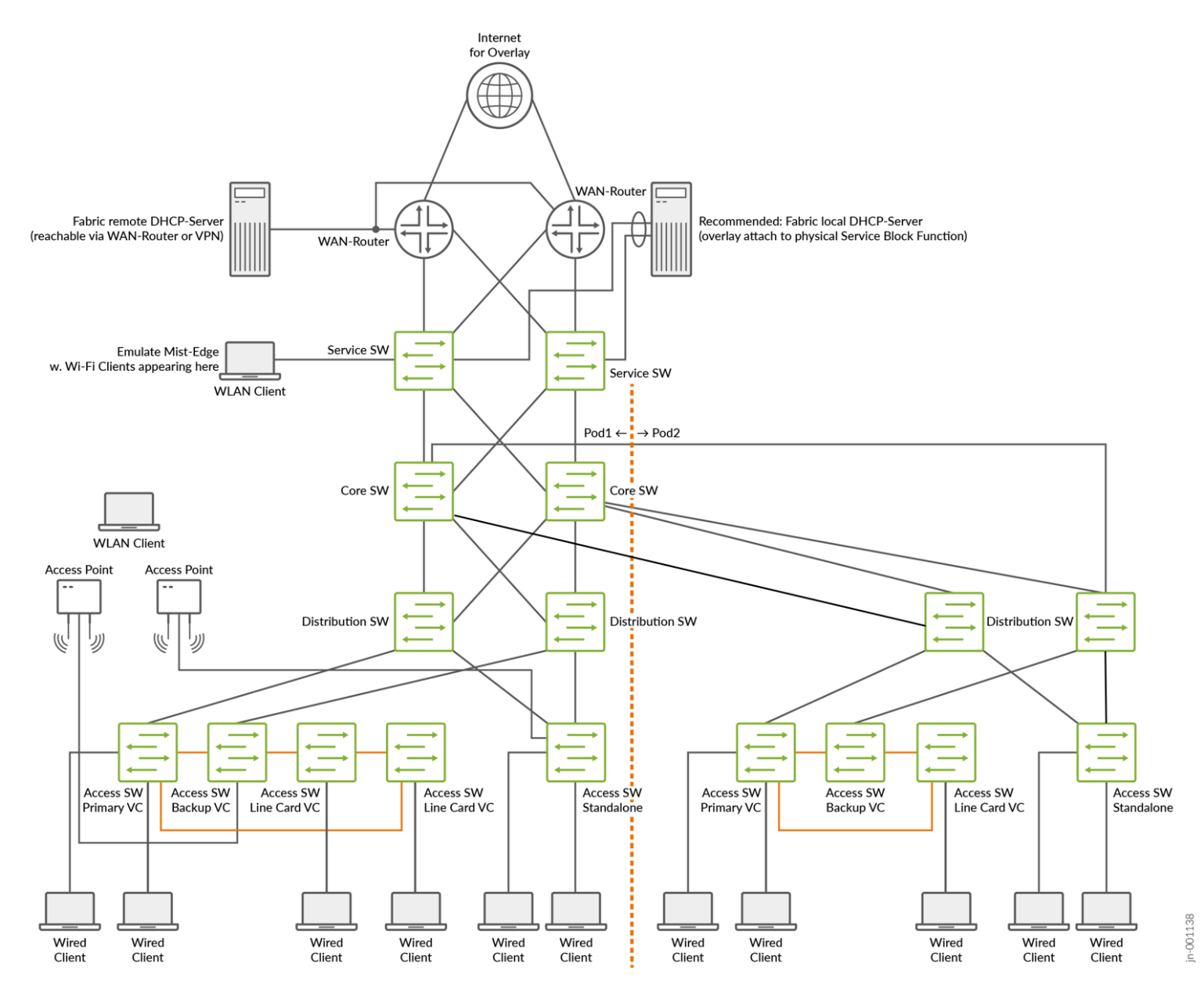
The approach we recommend is local integration as part of the fabric itself.
In the case of a campus fabric, the service leaf is called a service block function and, in the following example, a pair of physical switches north of where the DHCP server is attached to be an integral piece of the fabric.
The DHCP server can also manage leases for clients not in the same VRF as itself. However, as there is always VRF to VRF isolation inside the fabric, the packets will have to be exchanged through a WAN router.
When such a local integration is not possible, one can also try to integrate the DHCP server as an external element towards the fabric. This is what you see in the upper-left corner in the following figure:
What Needs to be Considered When Using External DHCP Servers?
When integrating external DHCP servers into the fabric, there are two critical points to keep in mind for this approach to succeed:
- Keep the latency between the fabric and DHCP servers as low as possible. Do not consider operating the DHCP server in a public cloud environment if you do not know the latency impact. Some DHCP clients can be very aggressive when requesting a lease, which can cause unanswered DHCP lease requests to stack up in a high latency environment, overloading the DHCP server. Since the DHCP client behavior is hardly influenceable at the fabric level, we recommend testing the design with a focus on the entire round-trip latency times before putting the fabric into production.
-
No form of network address translation (NAT) is
supported between the fabric and the DHCP server. The
reason for this is explained in the following excerpt from IETF RFC
2131 describing how a DHCP server must respond to client
requests. Remember, “giaddr” is the embedded gateway IP
address:
4.1 Constructing and sending DHCP messages
.
If the 'giaddr' field in a DHCP message from a client is non-zero,
the server sends any return messages to the 'DHCP server' port on the
BOOTP relay agent whose address appears in 'giaddr'.
.
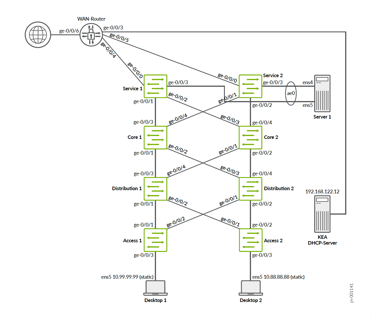
You may not be aware what this RFC description means, so we’ve provided an example of traffic using a Microsoft DHCP server that does not respond to SNATed DHCP requests in accordance with the RFC.
Here is the original source IP and port from the access switch created for the relay packet:
tcpdump -nnvvi fabric3 'port 4789 and udp[8:2] = 0x0800 and udp[11:4] = 11099'
tcpdump: listening on fabric3, link-type EN10MB (Ethernet), capture size 262144 bytes
12:48:50.799126 IP (tos 0x0, ttl 63, id 0, offset 0, flags [DF], proto UDP (17), length 419)
    172.16.254.6.42357 > 172.16.254.1.4789: [no cksum] VXLAN, flags [I] (0x08), vni 11099
IP (tos 0x0, ttl 64, id 27564, offset 0, flags [none], proto UDP (17), length 369)
    10.99.99.1.67 > 192.168.10.11.67: [udp sum ok] BOOTP/DHCP, Request from 52:54:00:d8:d1:04, length 341, xid 0x892af3d, Flags [none] (0x0000)
          Gateway-IP 10.99.99.1
          Client-Ethernet-Address 52:54:00:d8:d1:04
          Vendor-rfc1048 Extensions
            Magic Cookie 0x63825363
            DHCP-Message Option 53, length 1: Discover
            Hostname Option 12, length 8: "desktop1"
            Parameter-Request Option 55, length 13:
              Subnet-Mask, BR, Time-Zone, Default-Gateway
              Domain-Name, Domain-Name-Server, Option 119, Hostname
              Netbios-Name-Server, Netbios-Scope, MTU, Classless-Static-Route
              NTP
            Agent-Information Option 82, length 39:
              Circuit-ID SubOption 1, length 4: 1099
              Unknown SubOption 9, length 31:
                0x0000:  0000 0a4c 1a04 1849 5242 2d69 7262 2e31
                0x0010:  3039 393a 6d67 652d 302f 302f 332e 30
When the WAN router applies the SNAT to the forwarded discover message, it changes the source IP and port as follows:
tcpdump -nnvvi br0 'host 192.168.10.11'
12:40:46.545512 IP (tos 0x0, ttl 63, id 5475, offset 0, flags [none], proto UDP (17), length 369)
    192.168.10.169.28594 > 192.168.10.11.67: [udp sum ok] BOOTP/DHCP, Request from 52:54:00:d8:d1:04, length 341, xid 0x78caf527, secs 7, Flags [none] (0x0000)
          Gateway-IP 10.99.99.1
          Client-Ethernet-Address 52:54:00:d8:d1:04
          Vendor-rfc1048 Extensions
            Magic Cookie 0x63825363
            DHCP-Message Option 53, length 1: Discover
            Hostname Option 12, length 8: "desktop1"
            Parameter-Request Option 55, length 13:
              Subnet-Mask, BR, Time-Zone, Default-Gateway
              Domain-Name, Domain-Name-Server, Option 119, Hostname
              Netbios-Name-Server, Netbios-Scope, MTU, Classless-Static-Route
              NTP
            Agent-Information Option 82, length 39:
              Circuit-ID SubOption 1, length 4: 1099
              Unknown SubOption 9, length 31:
                0x0000:  0000 0a4c 1a04 1849 5242 2d69 7262 2e31
                0x0010:  3039 393a 6d67 652d 302f 302f 332e 30
The DHCP server’s response, however, answers back to the original embedded gateway IP on port 67, which was the original source IP inside the fabric before the SNAT was applied:
12:40:46.545962 IP (tos 0x0, ttl 128, id 30987, offset 0, flags [none], proto UDP (17), length 359)
    192.168.10.11.67 > 10.99.99.1.67: [bad udp cksum 0x397c -> 0x81a7!] BOOTP/DHCP, Reply, length 331, xid 0x78caf527, Flags [none] (0x0000)
          Your-IP 10.99.99.10
          Server-IP 192.168.10.11
          Gateway-IP 10.99.99.1
          Client-Ethernet-Address 52:54:00:d8:d1:04
          Vendor-rfc1048 Extensions
            Magic Cookie 0x63825363
            DHCP-Message Option 53, length 1: Offer
            Subnet-Mask Option 1, length 4: 255.255.255.0
            RN Option 58, length 4: 345600
            RB Option 59, length 4: 604800
            Lease-Time Option 51, length 4: 691200
            Server-ID Option 54, length 4: 192.168.10.11
            Default-Gateway Option 3, length 4: 10.99.99.1
            Domain-Name-Server Option 6, length 8: 8.8.8.8,9.9.9.9
            Agent-Information Option 82, length 39:
              Circuit-ID SubOption 1, length 4: 1099
              Unknown SubOption 9, length 31:
                0x0000:  0000 0a4c 1a04 1849 5242 2d69 7262 2e31
                0x0010:  3039 393a 6d67 652d 302f 302f 332e 30
This packet will never arrive back at the SNAT firewall.
root@wanrouter> show security flow session destination-prefix 192.168.10.11
Session ID: 22116, Policy name: default-permit/5, Timeout: 50, Valid
  In: 10.99.99.1/67 --> 192.168.10.11/67;udp, Conn Tag: 0x0, If: ae0.1099, Pkts: 72, Bytes: 26568,
  Out: 192.168.10.11/67 --> 192.168.10.169/6673;udp, Conn Tag: 0x0, If: ge-0/0/0.0, Pkts: 0, Bytes: 0,
Optimizations in Junos OS to Help Your DHCP Relay Design
Through the Junos OS configuration, a couple of statements help to optimize your design. We present the critical ones here in case you want to know why the fabric is automatically configuring those:
In the Junos OS configuration, a “forward-only” statement is needed to prevent the device from monitoring uncontrolled DHCP traffic.
set groups top routing-instances <vrf-name> forwarding-options dhcp-relay forward-only
In the Junos OS configuration, the “relay-option-82 circuit-id vlan-id-only” statement synchronizes the behavior of QFX and EX switches when forwarding option 82 DHCP traffic (by default, they use different attributes). Also, this attribute then no longer adds unwanted interface information such as "IRB-irb.1099:ae10.0" or "IRB-irb.1099:vtep.32769". With this configuration added, only the VLAN ID is reported, easing the string parsing in this field, which we leverage for the Linux KEA DHCP server to assign the right lease.
set groups top routing-instances <vrf-name> forwarding-options dhcp-relay group <vlan-name> relay-option-82 circuit-id vlan-id-only
The Junos OS configuration statement “relay-option-82 server-id override” is described here and is needed in our environment. It helps the Microsoft DHCP server using sub-option 5 to determine the source of the packet and choose the right pool to assign.
set groups top routing-instances <vrf-name> forwarding-options dhcp-relay group <vlan-name> relay-option-82 server-id override
The Junos OS configuration statement “route-suppression destination” is needed when using loopback IPs as gateway IPs. It is not used for virtual gateway address static IPs as gateway IPs.
set groups top routing-instances <vrf-name> forwarding-options dhcp-relay group <vlan-name> route-suppression destination
In the Junos OS configuration, the fabric configures all IRB interfaces now with the “no-dhcp-flood” option. This helps to limit the MAC broadcast of the client so that not all DHCP relay devices receive the same request from the client duplicated. Without this option in place, as all client requests are broadcast packets in a VLAN, the original request gets duplicated through VXLAN and sent to all fabric nodes which have that VRF configured, which then perform DHCP relay towards the WAN router.
set interfaces irb unit <vlan-id> no-dhcp-flood
Should you use the vJunos-switch as a virtual switch instance in a lab, it is known that while the “no-dhcp-flood” option can be configured on a virtual switch, it is not currently implemented. Hence, you may observe flooding and the wrong gateway IP address used. However, that should not affect your ability to test this. It’s just a known limitation of the vJunos-switch.