APPENDIX: Example DHCP Relay in EVPN Multihoming Fabric
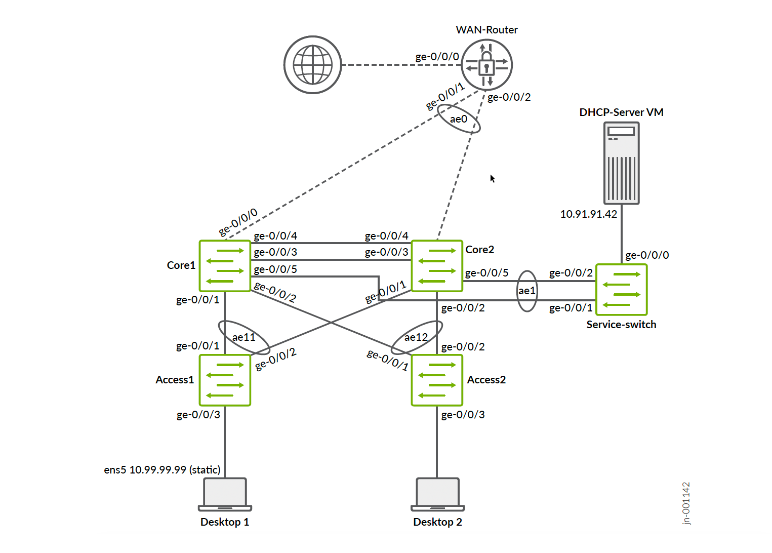
Following is an example lab design to test DHCP relay in an EVPN multihoming virtual gateway fabric with the following configuration:
- Fabric type = EVPN multihoming.
- Overlay loopback pool configured = N/A (static IRB IP addresses used as gateway IP addresses)
- WAN router integration = was not performed yet at this point of testing.
- DHCP server location = Integrated with the fabric through a virtual service block function.
- DHCP server reachability = Inside the fabric between different VLANs assigned to the same VRF.
- Third-party DHCP server used = Microsoft Windows 2022 DHCP server as VM.
The additional server switch was only added because when Microsoft Windows 2022 is installed in a VM, LACP bundling is not available for “team” interfaces. Hence, this was the better option to translate between these two worlds.
The configuration example shown below is only showing configuration relevant to the DHCP relay integration to make it brief. The full workflow can be deduced from available JVDs and extensions posted already.
You can reuse the switch template we have provided by importing the JSON below to expedite progress with this configuration:
{
  "ntp_servers": [],
  "dns_servers": [
    "8.8.8.8",
    "9.9.9.9"
  ],
  "dns_suffix": [],
  "additional_config_cmds": [],
  "networks": {
    "vlan1099": {
      "vlan_id": 1099,
      "subnet": "10.99.99.0/24"
    },
    "vlan1091": {
      "vlan_id": "1091",
      "subnet": "10.91.91.0/24",
      "subnet6": ""
    }
  },
  "port_usages": {
    "vlan1099": {
      "mode": "access",
      "disabled": false,
      "port_network": "vlan1099",
      "voip_network": null,
      "stp_edge": false,
      "all_networks": false,
      "networks": null,
      "port_auth": null,
      "speed": "auto",
      "duplex": "auto",
      "mac_limit": 0,
      "persist_mac": false,
      "poe_disabled": false,
      "enable_qos": false,
      "storm_control": {},
      "mtu": 9014,
      "description": "",
      "disable_autoneg": false
    },
    "vlan1091": {
      "disabled": false,
      "mode": "access",
      "port_network": "vlan1091",
      "voip_network": null,
      "stp_edge": false,
      "stp_p2p": false,
      "stp_no_root_port": false,
      "mac_auth_protocol": null,
      "all_networks": false,
      "networks": null,
      "port_auth": null,
      "allow_multiple_supplicants": null,
      "enable_mac_auth": null,
      "mac_auth_only": null,
      "guest_network": null,
      "bypass_auth_when_server_down": null,
      "dynamic_vlan_networks": null,
      "speed": "auto",
      "duplex": "auto",
      "mac_limit": 0,
      "persist_mac": false,
      "poe_disabled": false,
      "enable_qos": false,
      "storm_control": {},
      "mtu": 9014,
      "description": "",
      "disable_autoneg": false
    },
    "dynamic": {
      "mode": "dynamic",
      "reset_default_when": "link_down",
      "rules": []
    }
  },
  "switch_matching": {
    "enable": true,
    "rules": [
      {
        "name": "core",
        "port_config": {
          "ge-0/0/5": {
            "usage": "vlan1091",
            "dynamic_usage": null,
            "critical": false,
            "description": "",
            "no_local_overwrite": true,
            "aggregated": true,
            "ae_disable_lacp": false,
            "ae_lacp_force_up": false,
            "ae_lacp_slow": false,
            "ae_idx": 1,
            "esilag": true
          }
        },
        "additional_config_cmds": [
          "set groups top routing-instances customera forwarding-options dhcp-relay forward-only",
          "set groups top routing-instances customera forwarding-options dhcp-relay group vlan1099 relay-option-82 circuit-id vlan-id-only",
          "set groups top routing-instances customera forwarding-options dhcp-relay group vlan1099 relay-option-82 server-id-override",
          "",
          ""
        ],
        "oob_ip_config": {
          "type": "dhcp",
          "use_mgmt_vrf": false
        },
        "ip_config": {
          "type": "dhcp",
          "network": "default"
        },
        "port_mirroring": {},
        "match_name[0:4]": "core"
      }
    ]
  },
  "switch_mgmt": {
    "config_revert_timer": 10,
    "root_password": "juniper123",
    "protect_re": {
      "enabled": false
    },
    "tacacs": {
      "enabled": false
    }
  },
  "radius_config": {
    "auth_servers": [],
    "acct_servers": [],
    "auth_servers_timeout": 5,
    "auth_servers_retries": 3,
    "fast_dot1x_timers": false,
    "acct_interim_interval": 0,
    "auth_server_selection": "ordered",
    "coa_enabled": false,
    "coa_port": ""
  },
  "vrf_config": {
    "enabled": false
  },
  "remote_syslog": {
    "enabled": false
  },
  "snmp_config": {
    "enabled": false
  },
  "dhcp_snooping": {
    "enabled": false
  },
  "acl_policies": [],
  "mist_nac": {
    "enabled": true,
    "network": null
  },
  "disabled_system_defined_port_usages": [],
  "bgp_config": null,
  "routing_policies": {},
  "port_mirroring": {},
  "name": "DHCPLab1"
}
Campus Fabric Dialogue Configuration
In the campus fabric dialogue configuration, it is important to configure:
- The correct fabric type = EVPN multihoming
- Virtual gateway v4 MAC address = Enabled (this makes debugging easier as there is not a global MAC address used across all VLANs).
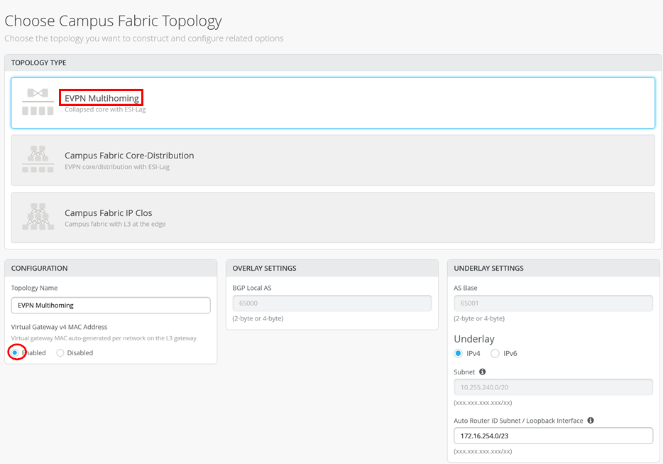
Assign the switches as collapsed cores and access switches in the next pane.
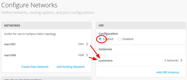
Then, in the “Networks” fabric dialogue, import two VLANs from the switch template.
- First VLAN (your desktop client requiring a lease will be
here):
- Name = vlan1099
- VLAN ID = 1099
- IPv4 subnet = 10.99.99.0/24
- IPv4 virtual gateway = 10.99.99.1
- Second VLAN (your DHCP server will be here):
- Name = vlan1091
- VLAN ID = 1091
- IPv4 subnet = 10.91.91.0/24
- IPv4 virtual gateway = 10.91.91.1
Then, add them to a single VRF:
- VRF Configuration = Enabled
- VRF:
- Name = customera
- Networks = vlan1099 and vlan1091
See the example:
Also add the DHCP relay information:
- DHCP relay = Enabled
- vlan1099:
- Network = vlan1099
- DHCP servers = 10.91.91.42
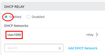
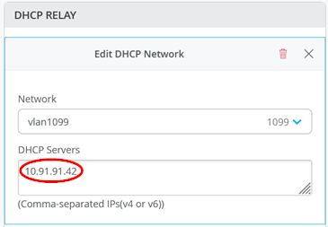
Ensure you always use this dialogue to configure DHCP relay in all campus fabric designs.
Finish the remaining dialogues so that Juniper Mist cloud pushes configuration to setup the fabric.
Access Switch Configuration
Our Desktop1 client is attached to the ge-0/0/3 interface on the Access1 switch through the following port configuration:
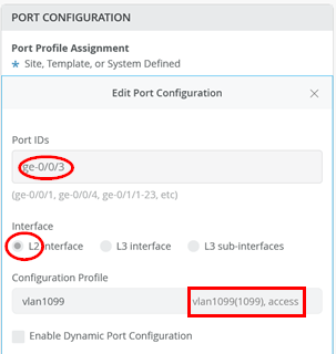
Based on this configuration, Juniper Mist cloud configures the following Junos OS configuration on the two collapsed core switches where the VRF is located in this fabric.
set groups top routing-instances customera instance-type vrf
set groups top routing-instances customera interface irb.1091
set groups top routing-instances customera interface irb.1099
set groups top routing-instances customera forwarding-options dhcp-relay server-group vlan1099 10.91.91.42
              set groups top routing-instances customera forwarding-options dhcp-relay group vlan1099 interface irb.1099
              set groups top routing-instances customera forwarding-options dhcp-relay group vlan1099 active-server-group vlan1099
set groups top routing-instances customera route-distinguisher 172.16.254.1:101
set groups top routing-instances customera vrf-target target:65000:101
set groups top routing-instances customera vrf-table-label
set groups top routing-instances customera routing-options auto-exportAt the time this document was created, not all options in Junos OS that are explained in the solution architecture chapter are created. Hence, we manually added the below additional Junos OS configuration on each collapsed core switch to have the optimal experience with the various DHCP servers tested.
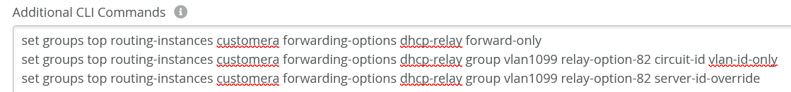
set groups top routing-instances customera forwarding-options dhcp-relay forward-only
set groups top routing-instances customera forwarding-options dhcp-relay group vlan1099 relay-option-82 circuit-id vlan-id-only
set groups top routing-instances customera forwarding-options dhcp-relay group vlan1099 relay-option-82 server-id-override
DHCP Server Integration
We decided to position a switch between the fabric and the DHCP server which was a virtual machine. Microsoft Windows does not support the usage of LACP when the server is a VM. However, we do that at the fabric side, hence we use a switch as a kind of translation element. Another advantage is that towards the VM, we then have a single interface containing all messages which makes it easier to debug.
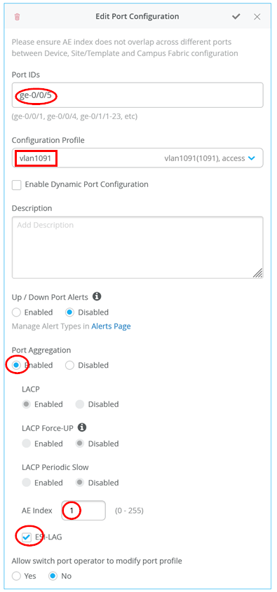
On the two collapsed core switches you configure:
- Port ID = ge-0/0/5
- Configuration profile = vlan1091
- Port aggregation = Enabled
- AE Index = 1
- ESI-LAG = Enabled
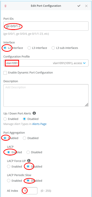
On the switch between the fabric and the DHCP server, you add a simple LAG configuration such as the one below:
- Port IDs = ge-0/0/1-2
- Interface = L2 interface
- Configuration profile = vlan1091
- Port aggregation = Enabled
- LACP = Enabled
- LACP force up = Disabled
- LACP periodic slow = Disabled
- AE Index = 1
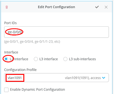
The single interface towards the DHCP server then:
- Port ID = ge-0/0/0
- Interface = L2 interface
- Configuration profile = vlan1091
Check the DHCP Server Itself
We assume that you have installed Microsoft Windows 2022 Server edition and applied the configuration example from above chapter APPENDIX: Example Microsoft DHCP server configuration used for testing . When this is done, you need to check the connection to the fabric to ensure the server gets the relay messages. In our case, the server had more than one interface for bootstrapping it:
PS C:\Users\Administrator> ipconfig
Windows IP Configuration
Ethernet adapter Ethernet:
Connection-specific DNS Suffix . :
Link-local IPv6 Address . . . . . : fe80::7d5a:47ae:2892:3d88%5
IPv4 Address. . . . . . . . . . . : 192.168.10.200
Subnet Mask . . . . . . . . . . . : 255.255.255.0
Default Gateway . . . . . . . . . :
Ethernet adapter Ethernet 2:
Connection-specific DNS Suffix . :
IPv4 Address. . . . . . . . . . . : 10.91.91.42
Subnet Mask . . . . . . . . . . . : 255.255.255.0
Default Gateway . . . . . . . . . : 10.91.91.1
# ping the VGA of this subnet
PS C:\Users\Administrator> ping 10.91.91.1
Pinging 10.91.91.1 with 32 bytes of data:
Reply from 10.91.91.1: bytes=32 time=1ms TTL=64
Reply from 10.91.91.1: bytes=32 time=1ms TTL=64
Reply from 10.91.91.1: bytes=32 time=1ms TTL=64
Reply from 10.91.91.1: bytes=32 time=1ms TTL=64
Ping statistics for 10.91.91.1:
Packets: Sent = 4, Received = 4, Lost = 0 (0% loss),
Approximate round trip times in milli-seconds:
Minimum = 1ms, Maximum = 1ms, Average = 1ms
# ping desktop1 client who should have a static IP-Address now
PS C:\Users\Administrator> ping 10.99.99.99
Pinging 10.99.99.99 with 32 bytes of data:
Reply from 10.99.99.99: bytes=32 time=2ms TTL=63
Reply from 10.99.99.99: bytes=32 time=2ms TTL=63
Reply from 10.99.99.99: bytes=32 time=2ms TTL=63
Reply from 10.99.99.99: bytes=32 time=1ms TTL=63
Ping statistics for 10.99.99.99:
Packets: Sent = 4, Received = 4, Lost = 0 (0% loss),
Approximate round trip times in milli-seconds:
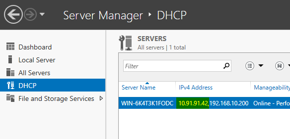
Minimum = 1ms, Maximum = 2ms, Average = 1msVerify that the server is listening on the IP address 10.91.91.42:
Final Test with a Wired Client
To complete the installation, perform a final test with a wired client. The initial state of our client is that it has a static IP address assigned and can communicate towards the internet:
root@desktop1:~# ifconfig ens5
ens5: flags=4163<UP,BROADCAST,RUNNING,MULTICAST> mtu 1500
inet 10.99.99.99 netmask 255.255.255.0 broadcast 10.99.99.255
inet6 fe80::5054:ff:feae:1e5b prefixlen 64 scopeid 0x20<link>
ether 52:54:00:ae:1e:5b txqueuelen 1000 (Ethernet)
RX packets 142 bytes 10653 (10.6 KB)
RX errors 0 dropped 51 overruns 0 frame 0
TX packets 158 bytes 14096 (14.0 KB)
TX errors 0 dropped 0 overruns 0 carrier 0 collisions 0
# do ping the VGA shared GW IP
root@desktop1:~# ping -c3 10.99.99.1
PING 10.99.99.1 (10.99.99.1) 56(84) bytes of data.
64 bytes from 10.99.99.1: icmp_seq=1 ttl=64 time=0.785 ms
64 bytes from 10.99.99.1: icmp_seq=2 ttl=64 time=1.03 ms
64 bytes from 10.99.99.1: icmp_seq=3 ttl=64 time=1.19 ms
--- 10.99.99.1 ping statistics ---
3 packets transmitted, 3 received, 0% packet loss, time 2003ms
rtt min/avg/max/mdev = 0.785/1.003/1.193/0.167 ms
# we ping the static IP of the one collapsed core switch
root@desktop1:~# ping -c3 10.99.99.2
PING 10.99.99.2 (10.99.99.2) 56(84) bytes of data.
64 bytes from 10.99.99.2: icmp_seq=1 ttl=64 time=0.766 ms
64 bytes from 10.99.99.2: icmp_seq=2 ttl=64 time=0.959 ms
64 bytes from 10.99.99.2: icmp_seq=3 ttl=64 time=0.824 ms
--- 10.99.99.2 ping statistics ---
3 packets transmitted, 3 received, 0% packet loss, time 2003ms
rtt min/avg/max/mdev = 0.766/0.849/0.959/0.080 ms
# we ping the static IP of the other collapsed core switch
root@desktop1:~# ping -c3 10.99.99.3
PING 10.99.99.3 (10.99.99.3) 56(84) bytes of data.
64 bytes from 10.99.99.3: icmp_seq=1 ttl=64 time=2.91 ms
64 bytes from 10.99.99.3: icmp_seq=2 ttl=64 time=1.35 ms
64 bytes from 10.99.99.3: icmp_seq=3 ttl=64 time=1.43 ms
--- 10.99.99.3 ping statistics ---
3 packets transmitted, 3 received, 0% packet loss, time 2004ms
rtt min/avg/max/mdev = 1.354/1.897/2.912/0.718 ms
# we review the ARP-cache for the 3 MAC-Addresses
root@desktop1:~# arp -an
? (10.99.99.3) at 2c:6b:f5:f8:9b:f0 [ether] on ens5
? (10.99.99.2) at 2c:6b:f5:ac:da:f0 [ether] on ens5
? (10.99.99.1) at 00:00:5e:e4:04:4b [ether] on ens5
# we try to test connectivity towards DHCP server
# Server must allow ICMP Ping which is not a default
root@desktop1:~# ping -c3 10.91.91.42
PING 10.91.91.42 (10.91.91.42) 56(84) bytes of data.
64 bytes from 10.91.91.42: icmp_seq=1 ttl=127 time=2.35 ms
64 bytes from 10.91.91.42: icmp_seq=2 ttl=127 time=2.32 ms
64 bytes from 10.91.91.42: icmp_seq=3 ttl=127 time=2.51 ms
--- 10.91.91.42 ping statistics ---
3 packets transmitted, 3 received, 0% packet loss, time 2003ms
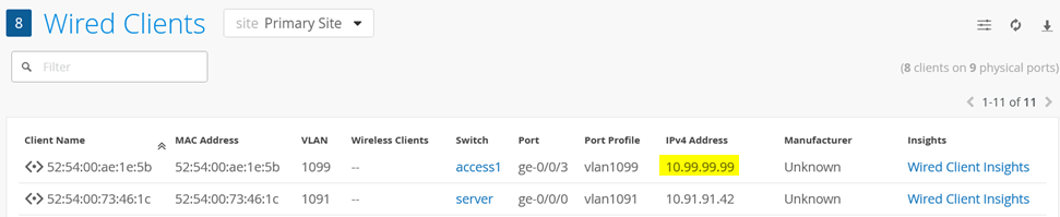
rtt min/avg/max/mdev = 2.322/2.392/2.506/0.081 msWe can see this client and its IP address in the Wired Client overview in the Juniper Mist portal:
Next, we unconfigure the static IP address and try to obtain a DHCP lease instead. The additional configuration below ensures that the client loses the static configuration and any prior knowledge of a DHCP lease. We then start up the DHCP client in the foreground to see a bit more of the debugging messages:
root@desktop1:~# ifconfig ens5 0.0.0.0 up
root@desktop1:~# pkill dhclient
root@desktop1:~# rm -f /var/lib/dhcp/*.leases
root@desktop1:~# dhclient -v ens5
Internet Systems Consortium DHCP Client 4.4.1
Copyright 2004-2018 Internet Systems Consortium.
All rights reserved.
For info, please visit https://www.isc.org/software/dhcp/
Listening on LPF/ens5/52:54:00:ae:1e:5b
Sending on   LPF/ens5/52:54:00:ae:1e:5b
Sending on   Socket/fallback
DHCPDISCOVER on ens5 to 255.255.255.255 port 67 interval 3 (xid=0x8599fa19)
DHCPOFFER of 10.99.99.63 from 10.99.99.3
DHCPREQUEST for 10.99.99.63 on ens5 to 255.255.255.255 port 67 (xid=0x19fa9985)
DHCPACK of 10.99.99.63 from 10.99.99.3 (xid=0x8599fa19)
bound to 10.99.99.63 -- renewal in 304223 seconds.
After a while (depending on local ARP age-outs), this change becomes visible in the Wired Client overview:
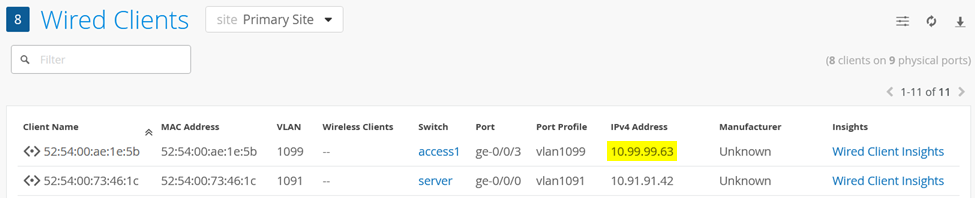
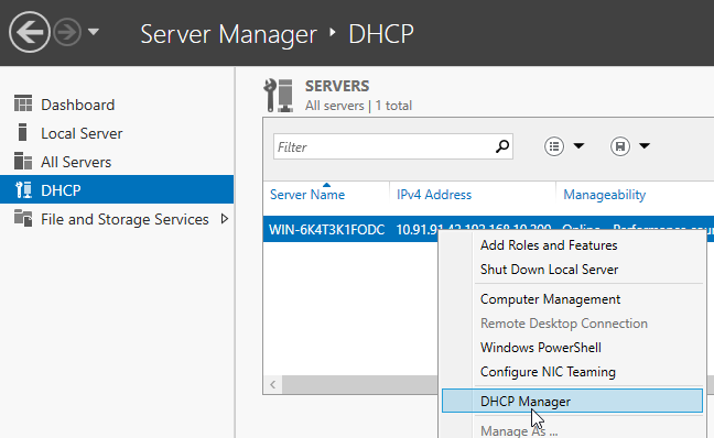
You can also see the lease handout on the DHCP server itself when opening the DHCP Manager as follows:
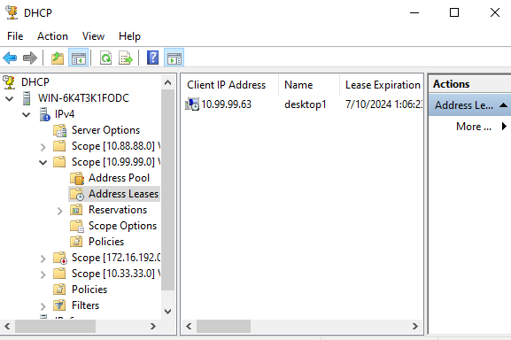
Below is an example of our client now appearing in the lease database of the DHCP server:
Example Trace of a DHCP Lease Handout
Below, you find the full sequence of a DHCP lease handout looking at the originating wired client and the DHCP server side getting the forwarded messages from the relay agent of the fabric. This was captured simultaneously through tcpdump.
We start the trace on the client sending the discover message through broadcast to the fabric relay agent:
10:14:30.770921 52:54:00:ae:1e:5b > ff:ff:ff:ff:ff:ff, ethertype IPv4 (0x0800), length 342: (tos 0x10, ttl 128, id 0, offset 0, flags [none], proto UDP (17), length 328)
    0.0.0.0.68 > 255.255.255.255.67: BOOTP/DHCP, Request from 52:54:00:ae:1e:5b, length 300, xid 0xb7d35449, Flags [none]
          Client-Ethernet-Address 52:54:00:ae:1e:5b
          Vendor-rfc1048 Extensions
            Magic Cookie 0x63825363
            DHCP-Message Option 53, length 1: Discover
            Hostname Option 12, length 8: "desktop1"
            Parameter-Request Option 55, length 13:
              Subnet-Mask, BR, Time-Zone, Default-Gateway
              Domain-Name, Domain-Name-Server, Option 119, Hostname
              Netbios-Name-Server, Netbios-Scope, MTU, Classless-Static-Route
              NTP
We now review the relay message arriving on the DHCP server with the embedded information from the fabric relay agent such as gateway IP and option 82:
10:14:30.772605 2c:6b:f5:f8:9b:f0 > 52:54:00:73:46:1c, ethertype IPv4 (0x0800), length 394: (tos 0x0, ttl 64, id 19866, offset 0, flags [none], proto UDP (17), length 380)
    10.99.99.3.67 > 10.91.91.42.67: BOOTP/DHCP, Request from 52:54:00:ae:1e:5b, length 352, xid 0xb7d35449, Flags [none]
          Gateway-IP 10.99.99.3
          Client-Ethernet-Address 52:54:00:ae:1e:5b
          Vendor-rfc1048 Extensions
            Magic Cookie 0x63825363
            DHCP-Message Option 53, length 1: Discover
            Hostname Option 12, length 8: "desktop1"
            Parameter-Request Option 55, length 13:
              Subnet-Mask, BR, Time-Zone, Default-Gateway
              Domain-Name, Domain-Name-Server, Option 119, Hostname
              Netbios-Name-Server, Netbios-Scope, MTU, Classless-Static-Route
              NTP
            Agent-Information Option 82, length 50:
              Circuit-ID SubOption 1, length 4: 1099
              Unknown SubOption 5, length 4:
                0x0000:  0a63 6303
              Unknown SubOption 11, length 4:
                0x0000:  0a63 6303
              Unknown SubOption 9, length 30:
                0x0000:  0000 0a4c 1904 1749 5242 2d69 7262 2e31
                0x0010:  3039 393a 7674 6570 2e33 3237 3639
The DHCP server responds towards the fabric relay agent with the offer for the client:
10:14:30.773018 52:54:00:73:46:1c > 00:00:5e:e4:04:43, ethertype IPv4 (0x0800), length 384: (tos 0x0, ttl 128, id 47992, offset 0, flags [none], proto UDP (17), length 370)
    10.91.91.42.67 > 10.99.99.3.67: BOOTP/DHCP, Reply, length 342, xid 0xb7d35449, Flags [none]
          Your-IP 10.99.99.63
          Server-IP 10.91.91.42
          Gateway-IP 10.99.99.3
          Client-Ethernet-Address 52:54:00:ae:1e:5b
          Vendor-rfc1048 Extensions
            Magic Cookie 0x63825363
            DHCP-Message Option 53, length 1: Offer
            Subnet-Mask Option 1, length 4: 255.255.255.0
            RN Option 58, length 4: 345600
            RB Option 59, length 4: 604800
            Lease-Time Option 51, length 4: 691200
            Server-ID Option 54, length 4: 10.99.99.3
            Default-Gateway Option 3, length 4: 10.99.99.1
            Domain-Name-Server Option 6, length 8: 8.8.8.8,9.9.9.9
            Agent-Information Option 82, length 50:
              Circuit-ID SubOption 1, length 4: 1099
              Unknown SubOption 5, length 4:
                0x0000:  0a63 6303
              Unknown SubOption 11, length 4:
                0x0000:  0a63 6303
              Unknown SubOption 9, length 30:
                0x0000:  0000 0a4c 1904 1749 5242 2d69 7262 2e31
                0x0010:  3039 393a 7674 6570 2e33 3237 3639
The fabric relay agent filters some of the information out (such as option 82) and forwards the offer as Layer 2 unicast to the client:
10:14:30.774479 2c:6b:f5:f8:9b:f0 > 52:54:00:ae:1e:5b, ethertype IPv4 (0x0800), length 332: (tos 0x0, ttl 64, id 19869, offset 0, flags [none], proto UDP (17), length 318)
    10.99.99.3.67 > 10.99.99.63.68: BOOTP/DHCP, Reply, length 290, xid 0xb7d35449, Flags [none]
          Your-IP 10.99.99.63
          Server-IP 10.91.91.42
          Client-Ethernet-Address 52:54:00:ae:1e:5b
          Vendor-rfc1048 Extensions
            Magic Cookie 0x63825363
            DHCP-Message Option 53, length 1: Offer
            Subnet-Mask Option 1, length 4: 255.255.255.0
            RN Option 58, length 4: 345600
            RB Option 59, length 4: 604800
            Lease-Time Option 51, length 4: 691200
            Server-ID Option 54, length 4: 10.99.99.3
            Default-Gateway Option 3, length 4: 10.99.99.1
            Domain-Name-Server Option 6, length 8: 8.8.8.8,9.9.9.9
Based on the previous offer received, the client now sends a request message through broadcast to the fabric relay agent:
10:14:30.776566 52:54:00:ae:1e:5b > ff:ff:ff:ff:ff:ff, ethertype IPv4 (0x0800), length 342: (tos 0x10, ttl 128, id 0, offset 0, flags [none], proto UDP (17), length 328)
    0.0.0.0.68 > 255.255.255.255.67: BOOTP/DHCP, Request from 52:54:00:ae:1e:5b, length 300, xid 0xb7d35449, Flags [none]
          Client-Ethernet-Address 52:54:00:ae:1e:5b
          Vendor-rfc1048 Extensions
            Magic Cookie 0x63825363
            DHCP-Message Option 53, length 1: Request
            Server-ID Option 54, length 4: 10.99.99.3
            Requested-IP Option 50, length 4: 10.99.99.63
            Hostname Option 12, length 8: "desktop1"
            Parameter-Request Option 55, length 13:
              Subnet-Mask, BR, Time-Zone, Default-Gateway
              Domain-Name, Domain-Name-Server, Option 119, Hostname
              Netbios-Name-Server, Netbios-Scope, MTU, Classless-Static-Route
              NTP
We now review the relay messages arriving on the DHCP server with the embedded information from the fabric relay agent such as the gateway IP and option 82 like the previously forwarded discover message:
10:14:30.778142 2c:6b:f5:f8:9b:f0 > 52:54:00:73:46:1c, ethertype IPv4 (0x0800), length 394: (tos 0x0, ttl 64, id 19872, offset 0, flags [none], proto UDP (17), length 380)
    10.99.99.3.67 > 10.91.91.42.67: BOOTP/DHCP, Request from 52:54:00:ae:1e:5b, length 352, xid 0xb7d35449, Flags [none]
          Gateway-IP 10.99.99.3
          Client-Ethernet-Address 52:54:00:ae:1e:5b
          Vendor-rfc1048 Extensions
            Magic Cookie 0x63825363
            DHCP-Message Option 53, length 1: Request
            Server-ID Option 54, length 4: 10.99.99.3
            Requested-IP Option 50, length 4: 10.99.99.63
            Hostname Option 12, length 8: "desktop1"
            Parameter-Request Option 55, length 13:
              Subnet-Mask, BR, Time-Zone, Default-Gateway
              Domain-Name, Domain-Name-Server, Option 119, Hostname
              Netbios-Name-Server, Netbios-Scope, MTU, Classless-Static-Route
              NTP
            Agent-Information Option 82, length 50:
              Circuit-ID SubOption 1, length 4: 1099
              Unknown SubOption 5, length 4:
                0x0000:  0a63 6303
              Unknown SubOption 11, length 4:
                0x0000:  0a63 6303
              Unknown SubOption 9, length 30:
                0x0000:  0000 0a4c 1904 1749 5242 2d69 7262 2e31
                0x0010:  3039 393a 7674 6570 2e33 3237 3639
The DHCP server responds with the lease acknowledgement back towards the fabric relay agent:
10:14:30.778534 52:54:00:73:46:1c > 00:00:5e:e4:04:43, ethertype IPv4 (0x0800), length 384: (tos 0x0, ttl 128, id 47993, offset 0, flags [none], proto UDP (17), length 370)
    10.91.91.42.67 > 10.99.99.3.67: BOOTP/DHCP, Reply, length 342, xid 0xb7d35449, Flags [none]
          Your-IP 10.99.99.63
          Gateway-IP 10.99.99.3
          Client-Ethernet-Address 52:54:00:ae:1e:5b
          Vendor-rfc1048 Extensions
            Magic Cookie 0x63825363
            DHCP-Message Option 53, length 1: ACK
            RN Option 58, length 4: 345600
            RB Option 59, length 4: 604800
            Lease-Time Option 51, length 4: 691200
            Server-ID Option 54, length 4: 10.99.99.3
            Subnet-Mask Option 1, length 4: 255.255.255.0
            Default-Gateway Option 3, length 4: 10.99.99.1
            Domain-Name-Server Option 6, length 8: 8.8.8.8,9.9.9.9
            Agent-Information Option 82, length 50:
              Circuit-ID SubOption 1, length 4: 1099
              Unknown SubOption 5, length 4:
                0x0000:  0a63 6303
              Unknown SubOption 11, length 4:
                0x0000:  0a63 6303
              Unknown SubOption 9, length 30:
                0x0000:  0000 0a4c 1904 1749 5242 2d69 7262 2e31
                0x0010:  3039 393a 7674 6570 2e33 3237 3639
The fabric relay agent filters some of the information out (such as option 82) and forwards the lease acknowledgement as Layer 2 unicast to the client:
10:14:30.780034 2c:6b:f5:f8:9b:f0 > 52:54:00:ae:1e:5b, ethertype IPv4 (0x0800), length 332: (tos 0x0, ttl 64, id 19875, offset 0, flags [none], proto UDP (17), length 318)
    10.99.99.3.67 > 10.99.99.63.68: BOOTP/DHCP, Reply, length 290, xid 0xb7d35449, Flags [none]
          Your-IP 10.99.99.63
          Client-Ethernet-Address 52:54:00:ae:1e:5b
          Vendor-rfc1048 Extensions
            Magic Cookie 0x63825363
            DHCP-Message Option 53, length 1: ACK
            RN Option 58, length 4: 345600
            RB Option 59, length 4: 604800
            Lease-Time Option 51, length 4: 691200
            Server-ID Option 54, length 4: 10.99.99.3
            Subnet-Mask Option 1, length 4: 255.255.255.0
            Default-Gateway Option 3, length 4: 10.99.99.1
            Domain-Name-Server Option 6, length 8: 8.8.8.8,9.9.9.9