Solution Architecture
The solution architecture deploys spine-leaf access fronthaul topology and midhaul/backhaul ring topologies that are combined to include aggregation and core roles with the services gateway comprising the complete xHaul infrastructure.
The architecture of this solution is fundamentally similar, with the inclusion of Paragon Automation and a DHCP server, to the Low Latency QoS Design for 5G Solution architecture, thereby enhancing the solution with advanced automation capabilities. The final goal of this JVD is to demonstrate how automation can enhance and optimize an existing network design. Therefore, the most important part of this JVD is not the network design, but Paragon Automation.
Figure 1 of the network topology shows the location of the automation systems (Paragon Automation and DHCP server). The automation systems are located at the service edge and are connected via out-of-band (OOB) network to every aggregation and core nodes. There is no OOB connectivity to any of the access nodes. Management and telemetry traffic for access nodes is all in-band.
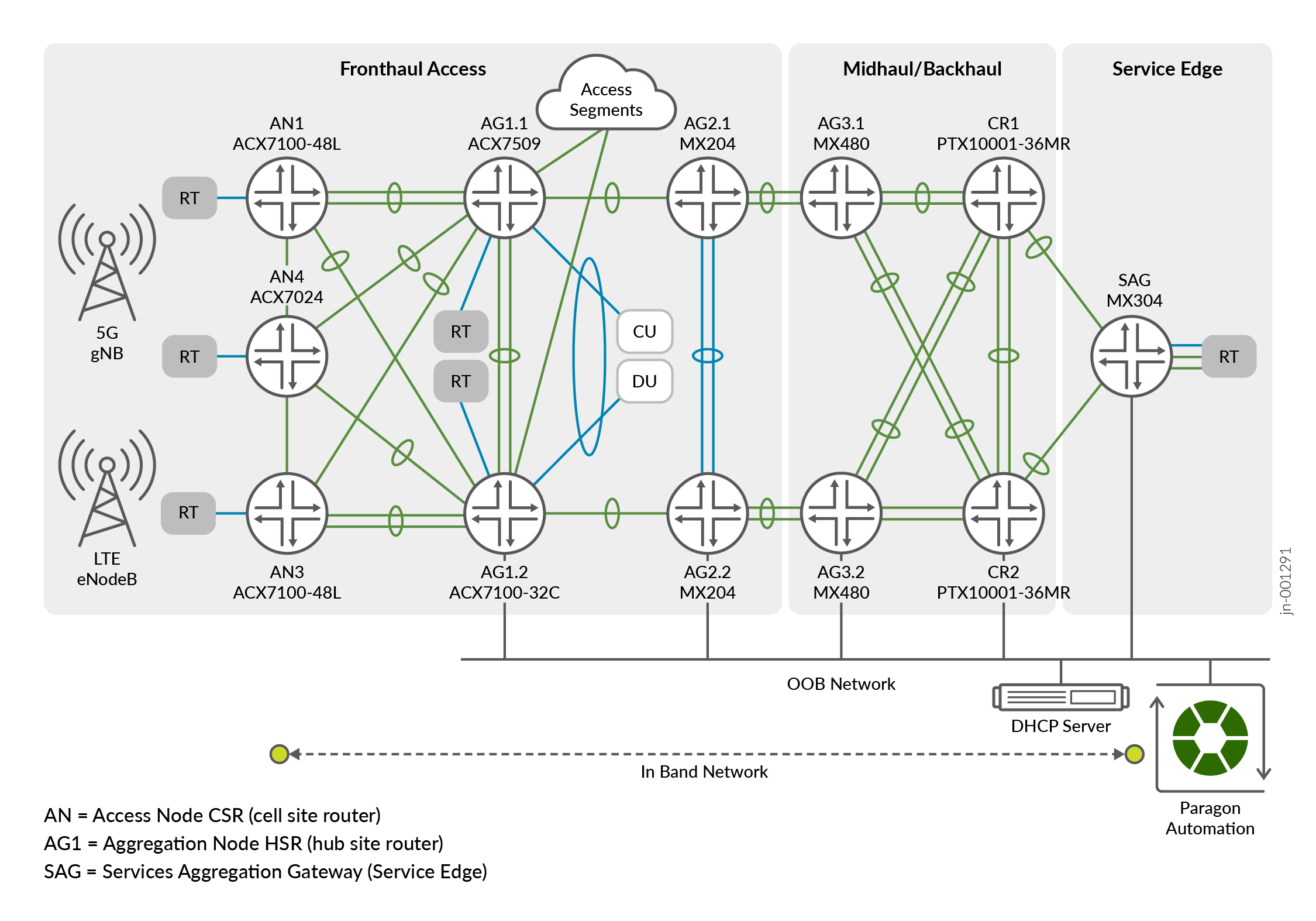
In the above figure,
- Paragon Automation insertion point is at the Service Edge location.
- DHCP server insertion point is also at the Service Edge location.
- Management traffic to Access Nodes (including DHCP) and Telemetry traffic is in-band.
- Aggregation and Core nodes have out-of-band (OOB) access to the DHCP server and Paragon Automation.
Paragon Automation
Paragon Automation is a collection of microservices that interact with one another through APIs and run within containers in a Kubernetes cluster. A Kubernetes cluster is a set of nodes or machines running containerized applications. Each node is a single machine, either physical (bare-metal server) or virtual (VMs).
A Kubernetes cluster comprises one or more primary and worker nodes.
- Control Plane Node (primary) The primary node performs the Kubernetes control plane functions.
- Compute node (worker)The worker node provides resources to run the pods. Worker nodes do not have control plane function.
During installation, you specify role of each node, and the installation playbooks install the corresponding components on each node accordingly.
Hardware Requirements
This section describes the minimum hardware resources that are required on each VM node in the Paragon Automation cluster. The compute, memory, and disk requirements of the cluster nodes can vary based on the intended capacity of the system. The intended capacity depends on the number of devices to be onboarded and monitored, types of sensors, and frequency of telemetry messages. If you increase the number of devices, you need higher CPU and memory capacities.
To get a scale and size estimates of a production deployment and to discuss detailed dimensioning requirements, contact your Juniper representative. Juniper Paragon Automation Release 2.3.0 supports a maximum of 800 devices.
| Paragon Hardware Details | ||
|---|---|---|
| Role | Description | Value |
| Primary/Worker cluster node | Number of vCPUs | 16 |
| Primary/Worker cluster node | Memory (GB) | 32 |
| Primary/Worker cluster node | Hard disk (GB) [SSD mandatory] | 750 + 250 |
Software Requirements
Use VMware ESXi 8.0 to deploy Paragon Automation. To install Paragon Automation for this JVD, you must create 4x virtual machine (VM) instances using the OVA (or OVF and .vmdk) files downloaded from the Juniper Software Downloads page (Type Paragon Automation in the All Products field and select the Paragon Automation Installation OVA from the application package section). These files contain the base operating system and all necessary software packages for VM creation and deployment of your Paragon Automation cluster on an ESXi server.
| Paragon Software Details | |||
|---|---|---|---|
| Software | Description | Release | Caveats |
| Paragon Automation | Paragon Automation version | 2.3.0 | Early Adopters release |
| Paragon cluster node OS | Cluster node Operating System |
Ubuntu 22.04 LTS (Jammy Jellyfish) |
Long Term Support |
Management Network Requirements
The management network requirements are as follows:
- All 4x Paragon nodes must be able to communicate with each other through SSH.
- All 4x Paragon nodes must be able to sync to an NTP server.
- SSH is enabled automatically during the VM creation, and you are asked to enter the NTP server address during the cluster creation. Ensure no firewall blocks NTP or SSH traffic between the nodes in case they are on different servers.
- Total seven IP-addresses for the installation of Paragon
Software suit (all in the same subnet).
- 4x interface IP addresses.
- 3x virtual IP addresses for:
- Generic IP address shared between gNMI, OC-TERM (SSH connections from devices), and the Web GUI. This is a general-purpose VIP address that is shared between multiple services and used to access Paragon Automation from outside the cluster.
- Paragon Active Assurance Test Agent Gateway (TAGW). This VIP address serves HTTP based traffic to the Paragon Active Assurance Test Agent endpoint. However, it is currently out of the scope of this JVD.
- PCE server. This VIP address is used to establish Path Computational Element Protocol (PCEP) sessions between Paragon Automation and the devices. The PCE server VIP configuration is necessary to view live topology updates in your network. However, it is also out of scope of this JVD.
The VIP addresses are added to the outbound SSH configuration (that is required for a device) to establish a connection with Paragon Automation. The outbound SSH commands for OC-TERM and gNMI both uses VIP addresses.
Hostnames mapped to the VIP addresses can enable your devices to connect to Paragon Automation using hostnames. However, you must ensure that the host names and the VIP addresses are correctly mapped in the DNS and your device is able to connect to the DNS server. If you configure Paragon Automation to use hostnames, the hostnames take precedence over VIP addresses and are added to the outbound SSH configuration used during onboarding devices.
Paragon Automation cluster can be configured using IPv6 addresses in addition to the existing IPv4 addresses. With IPv6 addressing, you can use IPv6 addresses for OC-TERM, gNMI, the Active Assurance TAGW, and access to the Web GUI. For more information, see Paragon Automation v2.3.0 Installation Guide .
In addition to the listed IP addresses and hostnames, you need the following information at the time of installation:
- Primary and secondary DNS server addresses for IPv4 (and IPv6 if needed).
- NTP server information.
For more information about the intra-cluster communication between nodes and communications from outside the cluster (Ports that firewalls MUST allow), see Paragon Automation v2.3.0 Installation Guide .
System Requirements
Once the Paragon Automation cluster has been successfully created and deployed, further configuration is necessary to fully integrate and optimize the system. The following steps are essential for completing the setup process:
- Create an Organization in the Paragon cluster. An organization in Paragon Automation represents a customer.
- Create different Sites within the Organization. A Site is the location of a device in an organization. While a site can have more than one device, a device can be associated with only one site.
- Fetch onboarding details such as Organization ID (orgID) and Site ID (siteID) for each access node to be used later at the ZTP process.
Use Cases
Paragon Automation focuses on targeted use cases and specifications gained from years of experience of network operations. As described earlier, the product is offered as license-based predefined use cases.
In this JVD, Paragon Automation focuses on the following use cases:
- Onboarding
- Trust and Compliance
- Device Lifecycle Management
- Observability

This includes:
- Automated onboarding process using ZTP.
- Device health visibility.
- Configuration, inventory, and software management.
By implementing an automated onboarding process, new devices can be seamlessly integrated with the existing or greenfield network, and onboarded into the management system, while minimizing manual configuration efforts and reducing the risk of human error, which cause delays, and increase in operational costs. This automated process guarantees that:
- Correct configuration is deployed.
- There is configuration consistency across devices acting in the same role.
- Devices are running the correct software images.
- There is version consistency across multiple devices.
As a result, not only is the deployment of new devices improved, but troubleshooting complexities are also reduced, and any necessary changes are completed faster and consistently across one or more devices.
Zero Touch Provisioning (ZTP)
Zero Touch Provisioning technology automates the setup and configuration of new devices remotely, eliminating the need for manual intervention. This streamlined process allows consistent, simultaneous, and automated configuration of network devices. They can be shipped factory-fresh to remote sites and local operators can connect these devices to the network without installing any image or configuring them.
ZTP in this JVD automates the onboarding process for access nodes in the metro network, accelerating the deployment of network infrastructure closer to customer sites. In conjunction with Paragon Automation, engineers can create standardized template configurations and deploy them to access devices using ZTP. This eliminates manual intervention, ensuring consistent configurations and minimizing human error. By streamlining the provisioning process, ZTP significantly reduces the time required to bring up network services, enabling faster service delivery to customers.
Pre-requisites
The pre-requisites to validate this Automation JVD are as follows:
- The Paragon Automation system must be up and running.
- Configured DHCP server.
- Configured DHCP relay agent.
- Low Latency QoS Design for 5G Solution architecture serves as the foundation for this JVD.
Figure 3 shows a flowchart depicting different steps involved in designing the topology for enabling ZTP provisioning:
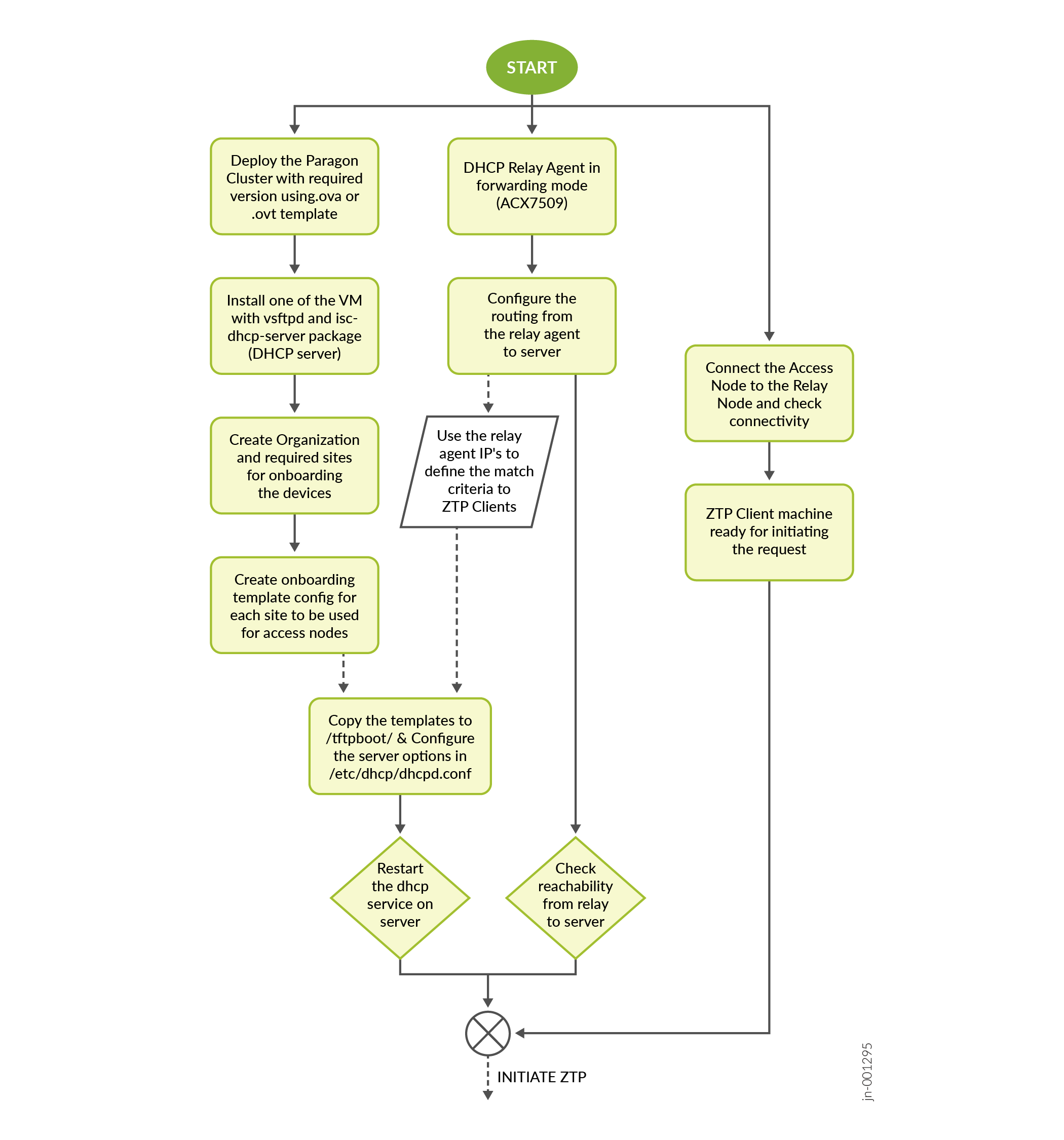
In the previous image, onboarding details such as Organization ID (orgID), Site ID (siteID) are fetched for each access node to be ZTP. Onboarding details are used to generate device specific configuration templates.
Onboarding Configuration Template (DHCP Server)
set system services ssh protocol-version v2
set system authentication-order password
set system login user jcloud-dev class super-user
set system login user jcloud-dev authentication encrypted-password $6$KuDFE1Bpb.rr/Bsr$1ledgVmhMkd1yHaPi7O0nrUI1rPBmNn.ZIVdHcawbZtuj6BundCKwAj9h2ymZNkONg9ItAqHk1yCm5VYqbQbu1
set system login user jcloud-dev authentication ssh-rsa "ssh-rsa AAAAB3NzaC1yc2EAAAADAQABAAABgQDAzwquzt6OGAl519B6CEo00KxRul2if68i6CVsvdeZCiZXcOjTZbOaayawAQAB46PpGU2D6nYkz1ytDDlIxwkuvA57nLs/bERg7jpxD…lient jcloud-dev secret e307faba64c8df37bf4bf74123b55cdb0468c7caf8c2925deb9f2c608232a347997e7b99c97126841736240e207b99cf16943a952bf4becdc7bd0f8e61eacacf
set system services outbound-ssh client jcloud-dev services netconf keep-alive retry 12 timeout 5
set system services outbound-ssh client jcloud-dev {{ paragon_IP }} port 2200 timeout 60 retry 1000
set system services outbound-ssh client jcloud-dev device-id {{ orgID }}.{{ siteID }}
delete system phone-home
DHCP is a network management protocol used to automate the process of configuring devices on IP networks. It enables devices to be automatically assigned IP addresses and other network settings, thereby greatly simplifying the management of networks. DHCP is essential in environments where devices frequently connect and disconnect from the network, such as in offices, homes, and public spaces.
When a device connects to a network, it sends out a DHCP Discover message to find available DHCP servers. The DHCP server responds with an offer, providing an IP address and other network settings such as subnet mask, default gateway, and DNS servers. The device then requests the offered configuration, and the DHCP server acknowledges the request, finalizing the configuration process. This seamless interaction ensures that devices can quickly and efficiently join the network without manual intervention.
The DHCP server used in this JVD is an Ubuntu server running Ubuntu 22.04.4 LTS connected to the OOB network with the following packages installed:
- vsftpd
- isc-dhcp-server
The following output shows those packages:
juniper@ubuntu-eop-vm:~$ dpkg -l | grep sftpd
ii  vsftpd     3.0.5-0ubuntu1.1     amd64   lightweight, efficient FTP server written for security
juniper@ubuntu-eop-vm:~$ dpkg -l | grep isc-dhcp-server
ii  isc-dhcp-server    4.4.1-2.3ubuntu2.4      amd64    ISC DHCP server for automatic IP address assignment
DHCP Server Configuration
Following is a sample configuration file that sets up a DHCP server to provide network parameters and configuration instructions to devices on the network:
set vendor-string = option vendor-class-identifier;
default-lease-time 600;
max-lease-time 7200;
log-facility local7;
option option-150 code 150 = ip-address;
option option-67 code 67 = text;
option option-66 code 66 = text;
option option_v4_sztp_redirect code 143 = string;
ddns-update-style none;
option space NEW_OP;
option NEW_OP.image-file-name code 0 = text;
option NEW_OP.config-file-name code 1 = text;
option NEW_OP.image-file-type code 2 = text;
option NEW_OP.transfer-mode code 3 = text;
option NEW_OP.ftp-server code 5 = text;
option NEW_OP.fetch-timeout code 7 = text;
option NEW_OP.fetch-timeout "300";
option agent.subscriber-id code 6 = text;
option NEW_OP-encapsulation code 43 = encapsulate NEW_OP;
subnet 20.6.0.60 netmask 255.255.255.254 {
 option routers 20.6.0.60;
 option subnet-mask 255.255.255.254;
 option NEW_OP.transfer-mode ftp;
 option NEW_OP.config-file-name “an1_script.py";
 option tftp-server-name "20.0.5.17";
 range 20.6.0.61 20.6.0.61;
}
subnet 20.0.5.0 netmask 255.255.255.0 {
 range 20.0.5.220 20.0.5.225;
}
General DHCP Server Settings
The following are the general DHCP server settings:
- Vendor-Specific Information: The server identifies itself with a specific vendor string.
- Lease Time: Clients can lease IP addresses for a maximum of 7200 seconds (2 hours).
- Logging: Log messages are sent to the local system's log facility (local7).
DHCP Relay Agent
The following are the steps to configure the AG nodes (for example, ACX7509) as a DHCP relay agent:
- Ensure proper routing is established between the AG node (for example, ACX7509) and the DHCP server.
- Configure the DHCP server (file: /etc/dhcp/dhcpd.conf)
to:
- Process DHCP requests from ZTP clients.
- Relay DHCP requests from pre-aggregation nodes (ACX7509).
- Assign IP addresses to ZTP clients.
- Provide necessary configuration options (for example, FTP path, filename) through DHCP offers.
- Create and store necessary template configurations for onboarding JVD in the /tftpboot/ directory, which is the default FTP path.
- Ensure the ZTP client is plugged into the same interface on the relay using which the server configuration is built to ensure smoother interaction with ZTP.
DHCP Relay Agent Configuration
Use the following sample configuration to set up a network device (AG1.x nodes) as a DHCP relay agent, forwarding DHCP requests from client devices to a specific DHCP server.
set forwarding-options dhcp-relay forward-only
set forwarding-options dhcp-relay server-group open-dhcp-server 20.0.5.17
set forwarding-options dhcp-relay active-server-group open-dhcp-server
set forwarding-options dhcp-relay group ztp-relay interface et-0/0/10.0
set forwarding-options dhcp-relay no-snoop
set interfaces et-0/0/10 unit 0 family inet address 20.6.0.60/31
ZTP Client Configuration for Access Node
In this implementation of Zero Touch Provisioning (ZTP) process, the client initiating the request requires two essential configuration files:
- Onboarding Configuration: Is defined under prerequisites in the system configuration as the minimum required configuration for Juniper device, which is usually referred as device baseline configuration (root password and configuration required to establish an SSH outbound connection to Paragon Automation).
- Client-Specific Configuration: Is relevant to the specific client. For example, access node configuration as outlined in Low Latency QoS Design for 5G Solution .
The following two methods can be employed to deliver these configurations:
-
Merged Configuration:
- Combine both configurations into a single "device.conf" file.
- Store this file on the DHCP server.
- Specify the "device.conf" filename within the server's dhcpd.conf file.
-
Python Automation (current implementation):
- Store the base configuration and JVD configuration for each access node in the /tftpboot/ directory on the DHCP server.
- When a ZTP request is made, the DHCP options trigger the transfer of a Python script to the access node.
- This script executes on-box automation that initiates FTP transfers for both the base and JVD configurations files. It also onboards as the onboarding configuration is part of base configuration stored on the server.
- This approach enables the re-use of base and JVD configuration templates as needed.
-rwxr-xr-x 1 root     root       1687901 Jan 10 07:07 ANx.configs
-rwxr-xr-x 1 regress  regress       2817 Jan 12 10:33 ANx_Onboarding.configs
-rwxr-xr-x 1 regress  regress       2662 Oct 22 14:53 anx_script.py
ZTP Specific Options
Alongside basic IP address allocation, DHCP includes various options that provide additional information, ensuring seamless network operation. These are the ZTP options used:
- Option 150: Specifies the IP address of the TFTP server, where configuration files are stored.
- Option 67 and 66: These options are commonly used for vendor-specific configuration information, but their specific usage depends on the vendor's implementation.
-
Option 143: This option indicates that the
following options are specific to ZTP.
- Options 0-7: These options define configuration file details, such as its name, type, and transfer method (FTP).
- Option 6: This option specifies the subscriber ID, which can be used for device identification and policy enforcement.
- Option 43: This option encapsulates the ZTP-specific options, ensuring they are delivered to the client.
- Network Subnet (Subnet 20.6.0.60): This subnet is configured for a specific device or group of devices, namely the ZTP Client. It assigns IP addresses from a specific range (20.6.0.61) and specifies the TFTP server address and configuration file name.
ZTP Process
Following is a ZTP process that operates after the devices are being set to factory default settings:
- The ZTP client (access node) boots up and sends a DHCP Discovery message through its connected interfaces.
- The pre-aggregation node (ACX7509) receives one of the DHCP
Discovery messages from the ZTP client from one of its connected
interfaces. It then forwards this message to the DHCP server,
acting as a relay agent. This allows the ZTP client to communicate
with the DHCP server even if they are not on the same network
segment.Note:
Communication is seen in a similar manner from Client to Relay and vice versa throughout the ZTP lifecycle.
- The DHCP server processes the request and sends a DHCP offer
message to the ZTP client through the relay. The offer includes:
- IP address.
- Subnet mask.
- Default gateway.
- DNS server address.
- FTP server address.
- Filename of the configuration file.
- The ZTP Client accepts the offer and requests for the details of the offer which are relayed to the server.
- DHCP Server acknowledges the request and assigns the IP address to the client and updates the lease table.
- The ZTP client retrieves the configuration file from the FTP server using the provided information.
Figure 4 describes the ZTP process:
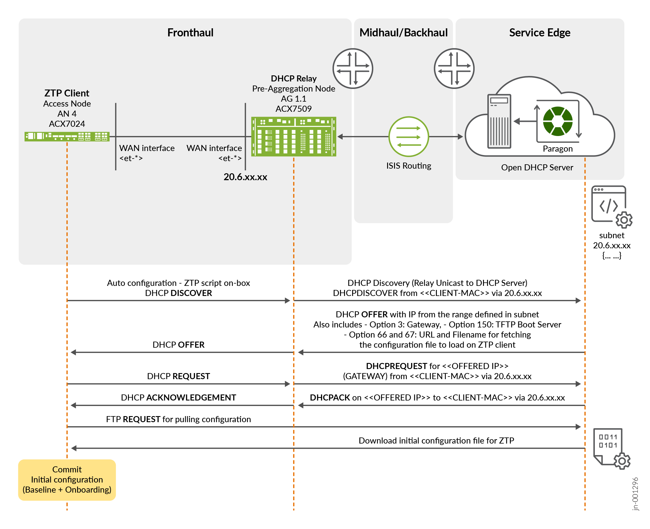
In the above figure:
- After downloading the configuration from the access node, the
ZTP client installs the configuration as retrieved from the server.
This configuration also contains the base configuration plus the
onboarding configuration that is needed by Paragon cluster to adopt
the device (SSH outbound connection) including the OrgId
and SiteId where the device is assigned to. Therefore,
once the configuration is committed, the device adoption process
begins and within a few minutes the device is being adopted
successfully in Paragon.
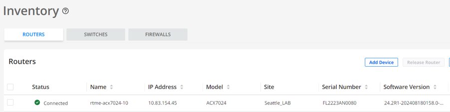
Figure 5: Paragon Inventory with Device Successfully Onboarded
- During the adoption process, a Configuration Template (CT) is associated with the device profile being onboarded. A network architect creates a device profile based on the role of the device in the network (an access node in this case; only access nodes are being onboarded as part of this solution). As device profiles can also be used to modify the configurations after a device is onboarded, the solution takes advantage of this approach to configure the final service of the access nodes. As the full-service configuration is not created from Paragon Automation, the following approach uses automation to provision the whole service configuration required by access node through another configuration file pulled out by the device at ZTP time. It contains all the service configurations (for example, /var/tmp/jvd.configs).
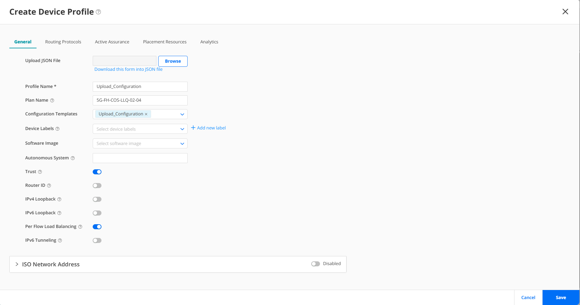
Figure 7 shows a process to create a configuration template to load a configuration file including the full-service configuration from LLQ JVD.
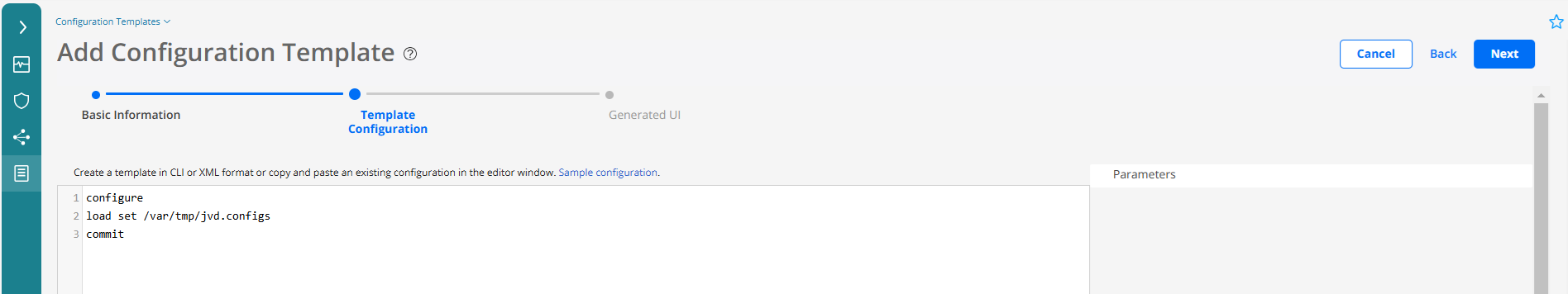
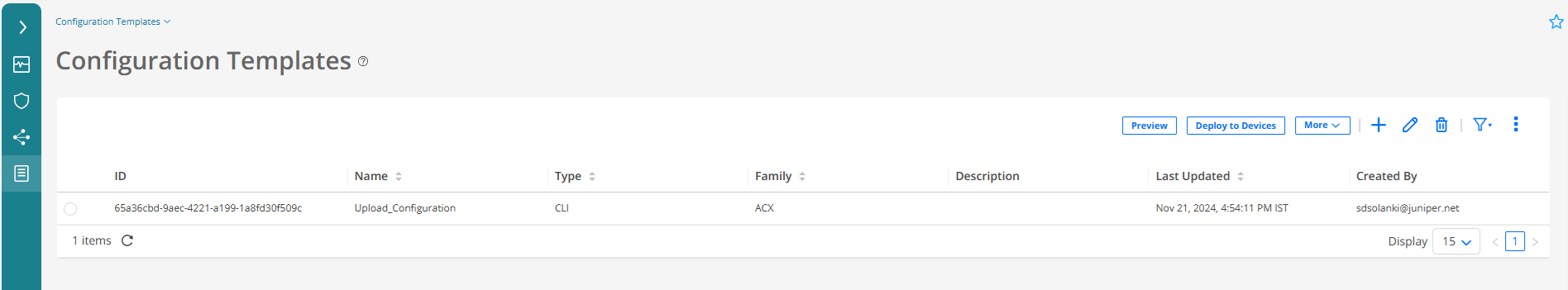
Once the configuration template has been created, it can be seen in the configuration template inventory. In this case, the configuration template is a workaround to provision the service configuration of the AN node stored in the /var/tmp/jvd.configs file downloaded by the python script while ZTP.
Networking Proposal
The proposed configuration establishes a dedicated Virtual Routing and Forwarding (VRF) instance named L3VPN_MGD for telemetry data collection and device management from Paragon Automation servers. The VRF is specially designed to facilitate the collection of data using gRPC communication, outbound SSH, static routing, and interface association.
This is the piece of configuration related to this L3VPN_MGD from one of the AG nodes:
AG nodes L3VPN_MGD Configuration
set routing-instances L3VPN_MGD instance-type vrf
set routing-instances L3VPN_MGD routing-options static route 11.11.11.11/32 next-hop 4.1.1.2
set routing-instances L3VPN_MGD routing-options static route 33.33.33.33/32 next-hop 5.1.1.2
set routing-instances L3VPN_MGD routing-options static route 44.44.44.44/32 next-hop 6.1.1.2
set routing-instances L3VPN_MGD forwarding-options dhcp-relay forward-only
set routing-instances L3VPN_MGD forwarding-options dhcp-relay server-group v4-server-group 7.1.1.2
set routing-instances L3VPN_MGD forwarding-options dhcp-relay active-server-group v4-server-group
set routing-instances L3VPN_MGD forwarding-options dhcp-relay group v4-client-group interface et-0/0/2.0
set routing-instances L3VPN_MGD forwarding-options dhcp-relay group v4-client-group interface et-0/0/4.0
set routing-instances L3VPN_MGD forwarding-options dhcp-relay group v4-client-group interface et-0/0/6.0
set routing-instances L3VPN_MGD forwarding-options dhcp-relay no-snoop
set routing-instances L3VPN_MGD interface et-0/0/2.0
set routing-instances L3VPN_MGD interface et-0/0/4.0
set routing-instances L3VPN_MGD interface et-0/0/6.0
set routing-instances L3VPN_MGD route-distinguisher 1.1.0.3:3000
set routing-instances L3VPN_MGD vrf-target target:63535:3000
set routing-instances L3VPN_MGD vrf-table-label
set interfaces et-0/0/2 unit 0 family inet address 6.1.1.1/24
set interfaces et-0/0/4 unit 0 family inet address 4.1.1.1/24
set interfaces et-0/0/6 unit 0 family inet address 5.1.1.1/24
The AG device, an Aggregation Node, as referred to in the previous section functions as a DHCP relay. It can operate within the default routing instance (in forward-only mode) or within a VRF, encapsulating all network traffic, including ZTP/DHCP requests. The described configuration utilizes a VRF (MGMT) for both DHCP relaying and forwarding management traffic to the SAG device.
Some DUTs in JVD establish management sessions (SSH, Telemetry) via out-band management network. There is an assumption that AN (Access Nodes) cannot access out-band network via physical connection. Because of this separate in-band management, network is configured via above mentioned VRF instance (L3VPN_MGD). On AN device, there are separate loopback interfaces configured with new units (other than default unit 0 in main routing instance) and placed in the management VRF. This VFR exists on all routers in topology particularly on SED (Service Edge Device) that is connected to Paragon Automation cluster of servers. New loopback interface routing information is propagated via VRF signaling mechanism to SED device. Also, static routing configuration is applied to Paragon cluster virtual machines so IP routing connectivity can be achieved between Paragon Automation cluster and new loopback address of AN node. Because of this design, management network resiliency is achieved as any link failure from AN to AGN node can be mitigated by existence of alternate path for underlay network (except total node isolation).
set system root-authentication encrypted-password "$1$ZUlES4dp$OUwWo1g7cLoV/aMWpHUnC/"
set interfaces lo0 unit 1 family inet address 11.11.11.11/32
set routing-instances VR-ONBOARD instance-type virtual-router
set routing-instances VR-ONBOARD routing-options instance-import IMPORT-FROM-MASTER-DIRECT
set routing-instances VR-ONBOARD interface lo0.1
set policy-options policy-statement IMPORT-FROM-MASTER-DIRECT from instance master
set policy-options policy-statement IMPORT-FROM-MASTER-DIRECT from route-filter 4.1.0.0/16 exact
set policy-options policy-statement IMPORT-FROM-MASTER-DIRECT then accept
set routing-options instance-import IMPORT-FROM-VR-ONBOARD-DIRECT
set routing-options auto-export family inet unicast
set policy-options policy-statement IMPORT-FROM-VR-ONBOARD-DIRECT from instance VR-ONBOARD
set policy-options policy-statement IMPORT-FROM-VR-ONBOARD-DIRECT from protocol direct
set policy-options policy-statement IMPORT-FROM-VR-ONBOARD-DIRECT then accept
set system services extension-service request-response grpc routing-instance VR-ONBOARD
set system services extension-service request-response grpc ssl local-certificate gnmi-terminator.juniper.net
set system services outbound-ssh routing-instance VR-ONBOARD
This configuration creates a VRF instance named VR-ONBOARD, which is a virtual router that maintains its own routing tables and forwarding tables, separate from the global routing table, on the AN router. The loopback interface, lo0 unit 1, is associated with the VRF instance to allow it to participate in the VRF routing and forwarding decisions. The loopback interface is configured with an IP address 11.11.11.11/32 to be used for identification. The route distinguisher and VRF target are set for the VRF instance to control the import and export of routes. This IP address can be used as the source or destination address for routing and streaming network data on the AN router.
After ZTP process is finished with management, VRF is provisioned on AN device and Paragon Automation onboarding starts.
Service Edge Configuration for Forwarding the Telemetry Data to Paragon Automation
This piece of configuration sets the gRPC extension service to operate within the L3VPN_MGD VRF.
set system services extension-service request-response grpc routing-instance L3VPN_MGD
Following sample configuration sets outbound SSH traffic to utilize the L3VPN_MGD VRF.
set system services outbound-ssh routing-instance L3VPN_MGD
This defines L3VPN_MGD as a VRF instance, enabling traffic isolation and improved security.
set routing-instances L3VPN_MGD instance-type vrf
This code defines a static route within the L3VPN_MGD VRF. The route points to the telemetry collector, ensuring that the telemetry traffic is correctly routed. In this case, the telemetry collector is the ingress VIP of our paragon cluster.
set routing-instances L3VPN_MGD routing-options static route 10.216.165.109/32 next-hop xe-0/1/5:0.0
This is the specified interface (xe-0/1/5:0.0) with L3VPN_MGD VRF. This interface is used for traffic related to telemetry collection.
set routing-instances L3VPN_MGD interface xe-0/1/5:0.0
This assigns a Route Distinguisher (RD) to the L3VPN_MGD VRF. The RD is a unique identifier used in VPN environments to distinguish routes belonging to different VRFs.
set routing-instances L3VPN_MGD route-distinguisher 1.1.0.11:3000
This configures the Route Target (RT) for the L3VPN_MGD VRF. The RT controls route import and export between different VRFs.
set routing-instances L3VPN_MGD vrf-target target:63535:3000
Configuration on Access Node
As the access nodes cannot be accessed directly as they are not part of the OOB network with respect to the Paragon Cluster, use the loopback interface as a stable endpoint for management traffic and routing protocols. By using the loopback interface, access node is always up and reachable, even if the physical interfaces or management interfaces are down.
set interfaces lo0 unit 2 family inet address 11.11.11.11/32
set routing-instances VR-ONBOARD instance-type virtual-router
set routing-instances VR-ONBOARD routing-options instance-import IMPORT-FROM-MASTER-DIRECT
set routing-instances VR-ONBOARD interface lo0.1
The above sample configuration creates a VRF instance named VR-ONBOARD, which is a virtual router that maintains its own routing tables and forwarding tables, separate from the global routing table, on the ACX7100 router. The loopback interface, lo0 unit 2, is associated with the VRF instance to allow it to participate in the VRF routing and forwarding decisions. The loopback interface is configured with an IP address, ‘11.11.11.11/32’ to be used for identification. The route distinguisher and VRF target are set for the VRF instance to control the import and export of routes. This IP address can be used as the source or destination address for routing and streaming network data on the ACX7100 router.
Configuration on SAG Node
The following sample configuration is required on the SAG node connecting Paragon and DHCP server with the L3VPN_MGD routing instance running from AG nodes to SAG.
[edit]

 regress@jvd-awan-mx304-d# show routing-instances L3VPN_MGD | display set

 set routing-instances L3VPN_MGD instance-type vrf

 set routing-instances L3VPN_MGD routing-options static route 10.216.165.109/32 next-hop xe-0/1/5:0.0

 set routing-instances L3VPN_MGD interface xe-0/1/5:0.0

 set routing-instances L3VPN_MGD interface xe-0/1/5:2.0

 set routing-instances L3VPN_MGD route-distinguisher 1.1.0.11:3000

 set routing-instances L3VPN_MGD vrf-target target:63535:3000

 set routing-instances L3VPN_MGD vrf-table-label

[edit]

 regress@jvd-awan-mx304-d# show interfaces xe-0/1/5:2.0

 family inet {

     address 7.1.1.1/24;

 }

[edit]

 regress@jvd-awan-mx304-d# show interfaces xe-0/1/5:0.0

 family inet {

     address 8.1.1.1/24;

 }

[edit]

 regress@jvd-awan-mx304-d#
Configuration on Paragon Cluster Nodes
Following is the sample network configuration on each Paragon cluster node (8.1.1.x), where x as 1 is the gateway configured and 2,3, 4, and 5 are the cluster node IPs. Also, 4.1.x is AN1, 5.1.x is AN3 and 6.1.x is AN4, and 11.11.11.11 and 33.33.33.33 and 44.44.44.44 are the loopback IPs for AN1, AN3, and AN4 nodes.
ens192: flags=4163<UP,BROADCAST,RUNNING,MULTICAST>  mtu 1500

         inet 8.1.1.2  netmask 255.255.255.0  broadcast 0.0.0.0

         inet6 fe80::250:56ff:feb5:2344  prefixlen 64  scopeid 0x20<link>

         ether 00:50:56:b5:23:44  txqueuelen 1000  (Ethernet)

         RX packets 4716  bytes 296885 (296.8 KB)

         RX errors 0  dropped 0  overruns 0  frame 0

         TX packets 36319  bytes 7873379 (7.8 MB)

         TX errors 0  dropped 0 overruns 0  carrier 0  collisions 0

 root@jvd-eop-vma:~# ip route | grep ens192

 4.1.1.0/24 via 8.1.1.1 dev ens192

 4.1.2.0/24 via  dev ens192

 5.1.1.0/24 via 8.1.1.1 dev ens192

 5.1.2.0/24 via 8.1.1.1 dev ens192

 6.1.1.0/24 via 8.1.1.1 dev ens192

 6.1.2.0/24 via 8.1.1.1 dev ens192

 8.1.1.0/24 dev ens192 proto kernel scope link src 8.1.1.2

 11.11.11.11 via 8.1.1.1 dev ens192

 33.33.33.33 via 8.1.1.1 dev ens192

 44.44.44.44 via 8.1.1.1 dev ens192

 root@jvd-eop-vma:~#