ON THIS PAGE
EVPN/VXLAN GPU Backend Fabric for Multitenancy – Implementation Options
Implementing GPU multitenancy in a data center requires a network architecture that ensures strong isolation, high throughput, and low latency across the shared infrastructure. This involves architectural considerations not only for the GPU backend fabric, which provides connectivity between GPUs belonging to each tenant, but also for the frontend fabric, where user access, job submission, orchestration, and authentication are handled, and the storage backend, which is responsible for delivering datasets, model checkpoints, and results to and from the GPU infrastructure. These components each require their own design strategies to ensure end-to-end performance, security, and multitenancy across the entire AI platform stack.
This JVD focuses specifically on the GPU backend fabric, which handles east-west traffic between GPUs across servers and is subject to the strictest performance and isolation requirements. EVPN/VXLAN is commonly used as the foundation for scalable multitenant environments, supporting two main design approaches: pure Type 5 services with IP-VRFs only, and VLAN-aware services with MAC-VRFs and symmetric IRB.
The pure Type 5 model follows the BGP EVPN IP Prefix Route specifications described in RFC 9136 (IP Prefix Advertisement in Ethernet VPN - EVPN). Traffic forwarding across the fabric relies entirely on Layer 3 routing, avoiding MAC learning and simplifying both the control plane and IP address management. In contrast, the VLAN-aware model uses Layer 2 overlays to extend bridging and VLAN segmentation across the fabric. Both approaches use routed underlay designs with VXLAN encapsulation, enabling flexible resource allocation and tenant isolation across multiple physical servers.
These two approaches are summarized in table 7 for both GPU Isolation and Server Isolation.
Table 7. EVPN/VXLAN models comparison
| FEATURES |
Pure RT5 EVPN/VXLAN (Recommended) |
VLAN-Aware EVPN/VXLAN service with MAC-VRF |
||
|---|---|---|---|---|
| Multi-tenancy Type |
GPU-Isolation (Per GPU multitenancy) |
Server Isolation (Per-server multitenancy) |
GPU-Isolation (Per GPU multitenancy) |
Server Isolation (Per-server multitenancy) |
| GPU Assignment (Tenant Resource Allocation) |
One or more GPU (but not all) per server assigned to multiple Tenants |
All GPUs (8) per server assigned to a single Tenant |
One or more GPU (but not all) per server assigned to multiple Tenants |
All GPUs (8) per server assigned to a single Tenant |
| Tenant GPU Distribution | A tenant can have one or more (but not all) GPUs on one or more servers. |
A tenant can have all the GPUs on one or more servers. |
A tenant can have one or more (but not all) GPUs on one or more servers. |
A tenant can have all the GPUs on one or more servers. |
| VLANs per serveró Leaf node Links | No VLANs | No VLANs | Each link is in a different VLAN and is assigned a different VNI. | Each link is in a different VLAN and is assigned a different VNI. |
| Interface configuration Mode and VLAN Mapping | Access-mode interfaces, server links in different RT5_IP-VRF | Access-mode interfaces, server links in different RT5_IP-VRF | Access-mode interfaces, server links in different MAC-VRF | Access-mode interfaces, server links in different MAC-VRF |
| IP addressing per serveró Leaf node Links |
Server links configured with:
8 x IP routed links |
Server links configured with:
8 x IP routed links |
Server links configured with:
|
Server links configured with:
|
| VRF and Routing Instances per tenant |
One RT5_IP-VRF only No MAC-VRF (on each leaf node where the GPUs assigned to tenant are connected) |
One RT5_IP-VRF only No MAC-VRF (on each leaf node where the GPUs assigned to tenant are connected) |
One RT5_IP-VRF & One MAC-VRF (on each leaf node where the GPUs assigned to tenant are connected) |
One RT5_IP-VRF & One MAC-VRF (on each leaf node where the GPUs assigned to tenant are connected) |
|
VNI Allocation per Tenant |
Single VNI per tenant | Single VNI per tenant | 8 x VNIs per tenant | 8 x VNIs per tenant |
| Anycast Gateway Configuration |
No Anycast Gateway (no IRB interfaces) |
No Anycast Gateway (no IRB interfaces) |
8 x Anycast IP Gateways (8 x IRB interfaces) | 8 x Anycast IP Gateways (8 x IRB interfaces) |
| EVPN Service Type | Pure/Pure RT5 EVPN/VXLAN design | Pure/Pure RT5 EVPN/VXLAN | VLAN-Aware EVPN/VXLAN service (with MAC-VRF) | VLAN-Aware EVPN/VXLAN service (with MAC-VRF) |
| ERB Design | No ERB | No ERB | ERB design without ESI_LAG | ERB design without ESI_LAG |
| Underlay BGP Configuration | Underlay IPv6 BGP Unnumbered | Underlay IPv6 BGP Unnumbered | Underlay IPv6 BGP Unnumbered | Underlay IPv6 BGP Unnumbered |
| IRB and Routing Strategy | Pure RT5 EVPN routing - no IRB interfaces | Pure RT5 EVPN routing - no IRB interfaces | Symmetric IRB – Type 5 | Symmetric IRB – Type 5 |
|
Congestion Control (DCQCN Type) |
Pure Type 5 DCQCN; VXLAN DCQCN | Pure Type 5 DCQCN; VXLAN DCQCN | Type 2 & 5 DCQCN; VXLAN DCQCN | Type 2 & 5 DCQCN; VXLAN DCQCN |
Pure RT5 EVPN/VXLAN - Server-Level Isolation (Per-Server Multitenancy)
In this design model, each physical server is dedicated entirely to a single tenant, meaning all GPUs (typically 8 per server) are assigned to one tenant only. This model simplifies resource allocation and isolation since there’s no sharing of GPU resources between tenants on a single server. A tenant can span across multiple servers, each of which fully belongs to that tenant.
Server-to-leaf links are configured as L3 links, in access mode (no VLAN tagging), and are assigned unique IP addresses (/31 IPv4, /127 or /64 IPv6). The recommended solution in this document prescribes automatically assigning /64 IPv6 addresses using SLAAC (Stateless Address Autoconfiguration ). This approach enables servers to self-configure their addresses without requiring manual edits to each server’s netplan configuration. Configuration options for IPv4 are covered in the Appendix
Each server-facing link is associated with the same Tenant’s RT5_IP-VRF routing instance across the leaf nodes within a stripe, according to Tenant’s assignments, as shown in Figure 36.
Figure 35: Pure RT5 EVPN/VXLAN - Server-Level Isolation
(Per-Server Multitenancy)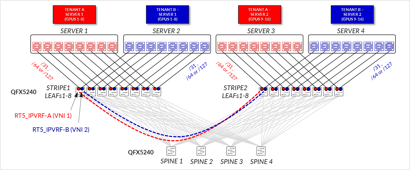
The fabric is configured as a pure EVPN/VXLAN Type 5 with no MAC-VRFs, IRBs, or anycast gateways involved.
BGP underlay sessions are established using IPv6 link-local addresses with automatic neighbor discovery, while overlay sessions are established between the IPv6 unicast addresses assigned to the loopback interfaces and advertised via the underlay. Congestion control is implemented using VXLAN-aware DCQCN, ensuring fairness and traffic stability.
If the overlay is using IPv4 addresses, the underlay needs to be configured using RFC 5549 to advertise IPv4 routes with IPv6 next-hops. See Appendix A – IPv4 Overlay Over IPv6 Underlay Fabric Implementation for more details.
Pure RT5 EVPN/VXLAN - GPU-Level Isolation (Per-GPU Multitenancy)
This model introduces finer-grained resource sharing by allowing GPUs within the same server to be allocated to different tenants. A tenant may receive one or more GPUs across one or multiple servers, but not all GPUs on any given server unless explicitly assigned. This GPU-level partitioning allows for more efficient use of server resources and is well-suited for environments with dynamic or fractional GPU demands. Despite the increased resource-sharing granularity, the server to leaf node connectivity remains the same.
Server-to-leaf links are still configured as L3 links, in access mode (no VLAN tagging), and are assigned unique IP addresses (/31 IPv4, /127 or /64 IPv6). The recommended solution in this document prescribes automatically assigning /64 IPv6 addresses using SLAAC (Stateless Address Autoconfiguration ). This approach allows servers to automatically configure their addresses, eliminating the need to manually edit each server’s netplan configuration. Configuration options for IPv4 are covered in the Appendix.
Each link in a server is mapped to a different Tenant’s RT5_IP-VRF routing instances across the leaf nodes within a stripe, according to Tenant’s assignments, as shown in Figure 36.
Figure 36: Pure RT5 EVPN/VXLAN – GPU Level Isolation (Per-GPU Multitenancy)
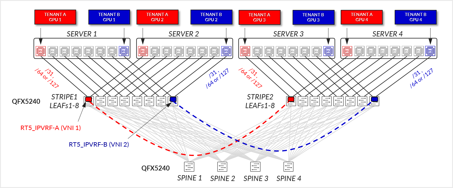
The fabric is still configured as a pure EVPN/VXLAN Type 5 with no MAC-VRFs, IRBs, or anycast gateways involved.
BGP underlay sessions are established using IPv6 link-local addresses with automatic neighbor discovery, while overlay sessions are established between the IPv6 unicast addresses assigned to the loopback interfaces and advertised via the underlay. Congestion control is implemented using VXLAN-aware DCQCN, ensuring fairness and traffic stability.
If the overlay is using IPv4 addresses, the underlay needs to be configured using RFC 5549 to advertise IPv4 routes with IPv6 next-hops. See Appendix A – IPv4 Overlay Over IPv6 Underlay Fabric Implementation for more details.
VLAN-Aware EVPN/VXLAN -Server-Level Isolation (Per-Server Multitenancy)
In this design model, each physical server is fully dedicated to a single tenant, meaning all GPUs (typically 8 per server) are assigned exclusively to that tenant. This approach simplifies resource allocation and ensures strong isolation, as there is no GPU resource sharing across tenants on the same server. A tenant may span multiple servers, each entirely allocated to that tenant.
Server-to-leaf links are configured as Layer 3 interfaces; each associated with a unique VLAN and VNI. The recommended solution in this document uses /64 IPv6 addresses automatically assigned via SLAAC (Stateless Address Autoconfiguration), eliminating the need for manual configuration of each server’s netplan file. IP addressing is allocated from larger pools (e.g., /24 for IPv4 and /64 for IPv6), with each link receiving its own anycast gateway (IRB) interface, resulting in 8 IRB interfaces per server. Each server-facing link is associated with the tenant’s MAC-VRF and IP-VRF routing instances across the leaf nodes within a stripe, according to the tenant’s assignment, as shown in Figure 37.
Figure 37: VLAN-aware EVPN/VXLAN – Server Level Isolation
(Per-Server Multitenancy) 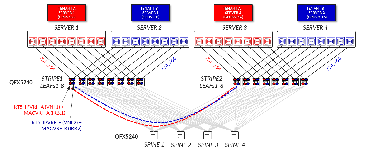
From a network design perspective, this use case relies on a VLAN-Aware EVPN/VXLAN service, with per-tenant separation using both MAC-VRFs and IP-VRFs. Each leaf switch hosting a tenant's servers maintains a pair of VRFs: a MAC-VRF for bridging and an RT5_IP-VRF for routing. The design follows a symmetric IRB model, supporting both EVPN Type 2 and Type 5 routes, and implements VXLAN-aware DCQCN for congestion management.
VLAN-Aware EVPN/VXLAN - GPU-Level Isolation (Per-GPU Multitenancy)
This design model enables finer-grained resource sharing by assigning individual GPUs within a server to different tenants. A single server can be shared across multiple tenants, each with access to a subset of GPUs rather than the entire server. This approach increases overall compute resource utilization while maintaining strong isolation between tenants.
Server-to-leaf links are configured as Layer 3 interfaces, each associated with a unique VLAN and VNI. IPv6 addresses are automatically assigned via SLAAC (/64 per interface), allowing the server to self-configure without requiring manual edits to its netplan file. IP addressing is allocated from larger pools (e.g., /24 for IPv4 and /64 for IPv6), with each GPU-facing link receiving its own anycast gateway (IRB) interface, resulting in 8 IRB interfaces per server. Each interface is associated with the tenant’s MAC-VRF and IP-VRF routing instances across the leaf nodes, according to the tenant’s assignment.
Figure 38: VLAN-aware EVPN/VXLAN - GPU-Level Isolation (Per-GPU
Multitenancy)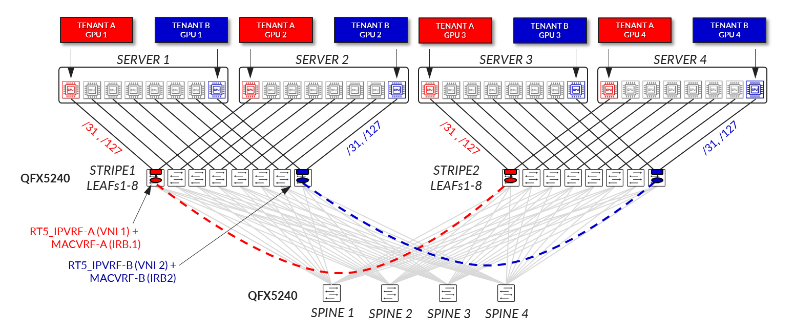
From a network design perspective, this use case also relies on a VLAN-Aware EVPN/VXLAN service, with per-tenant separation using both MAC-VRFs and IP-VRFs. Each leaf switch hosting the server’s GPU-assigned interfaces maintains a pair of VRFs: a MAC-VRF for bridging and an RT5_IP-VRF for routing. The design follows a symmetric IRB model, supports both EVPN Type 2 and Type 5 routes, and implements VXLAN-aware DCQCN to ensure fair and stable congestion control across the shared infrastructure.
Selecting the Best Approach
In the context of AI workloads such as training, inference, and GPU-as-a-Service (GPUaaS), the choice between a pure Type 5 and a VLAN-aware EVPN/VXLAN design can significantly impact operational efficiency. The pure Type 5 model is often better suited for large-scale AI training environments, where GPU resources are allocated in bulk, either per server or per tenant, and workloads are typically long running and tightly coupled. Its streamlined IP-based routing, stable addressing, and minimal control-plane overhead enable predictable performance and simplified automation across hundreds or thousands of servers. In contrast, the VLAN-aware model may be more appropriate for GPUaaS platforms, inference workloads, or multi-purpose environments where tenants run shorter, independent jobs and require granular isolation, dynamic L2 connectivity, or per-interface policy enforcement. The use of MAC-VRFs and anycast gateways provides flexibility for tenant-specific services, especially in use cases involving legacy applications, bare-metal workloads, or environments that need tenant-specific IP gateways. Ultimately, both models support GPU multitenancy, but the pure Type 5 design favors scale and simplicity, while the VLAN-aware design offers flexibility and fine-grained control.
This JVD focuses on the Pure RT5 EVPN/VXLAN implementation. Thus, the rest of the document will cover all the details for the Pure RT5 EVPN/VXLAN - Server-Level Isolation (Per-Server Multitenancy) and Pure RT5 EVPN/VXLAN - GPU-Level Isolation (Per-GPU Multitenancy) options.