Appendix D – How to Run NCCL Tests Using Autoconfigured IPv6 Address
To run a model or NCCL test using a global IPv6 addresses assigned either statically or automatically via SLAAC the value of the NCCL_IB_GID_INDEX variable must be adjusted.
Starting with NCCL 2.21, the GID index no longer needs to be specified manually. It is automatically handled based on the NCCL_SOCKET_FAMILY setting. If NCCL_SOCKET_FAMILY is set to AF_INET6 and IPv6 connectivity between hosts is in place, RoCEv2 traffic over IPv6 should work as expected.
The NCCL_IB_GID_INDEX variable defines the Global ID index used by RoCE (RDMA) communication. The default value is -1, which means that NCCL will automatically select the correct GID index based on the active link layer of the InfiniBand device. If the link layer is Ethernet (RoCE), NCCL will use the GID index that returns a GID with RoCE v2 support (usually GID index 3, depending on driver/firmware).
For more details you can review Nvidia’s Environment Variables documentation
To find the GID for the desired address, use the following command:
ibv_devinfo -vvv -d <mellanox-interface-name> | grep GID
To find the mellanox interface name you can use the following script:
jnpr@H100-01:~/scripts$ cat nvidia_map_iface_to_mlx.sh
# Script to map network interfaces to Mellanox interfaces

echo "Network Interface to Mellanox Interface Mapping:"

# Loop through each network interface in /sys/class/net/
for iface in $(ls /sys/class/net/); do
    if [ -d /sys/class/net/$iface/device/infiniband_verbs ]; then
        # Find the Mellanox interface by reading the ibdev file
        mlx_iface=$(cat /sys/class/net/$iface/device/infiniband_verbs/*/ibdev)
        echo "$iface => $mlx_iface"
    fi
done
Example:
jnpr@H100-01:/etc/netplan$ ibv_devinfo -vvv  -d mlx5_6 | grep GID
   GID[  0]:  fe80:0000:0000:0000:a288:c2ff:fe3b:506a, RoCE v1
   GID[  1]:  fe80::a288:c2ff:fe3b:506a, RoCE v2
   GID[  2]:  0000:0000:0000:0000:0000:ffff:0ac8:010a, RoCE v1
   GID[  3]:  ::ffff:10.200.1.10, RoCE v2
   GID[  4]:  FC00:200:0000:0002:a288:c2ff:fe3b:506a, RoCE v1
   GID[  5]:  FC00:200:0:2:a288:c2ff:fe3b:506a, RoCE v2

jnpr@H100-01:~/scripts$ ./nvidia_map_iface_to_mlx.sh | egrep "gpu|Map"
Network Interface to Mellanox Interface Mapping:
gpu0_eth => mlx5_11
gpu1_eth => mlx5_6
gpu2_eth => mlx5_10
gpu3_eth => mlx5_9
gpu4_eth => mlx5_4
gpu5_eth => mlx5_3
gpu6_eth => mlx5_5
gpu7_eth => mlx5_0
The easily find mapping information between the Mellanox interface names, the user assigned interface names (e.g. gpu0_eth), NICs, and the GPUs you can use the script find_pxb_gpu_nic_pairs.py which can be found under: https://github.com/Juniper/jvd/tree/main/Data%20Center/AIDC/backend/AI_ML_Multitenancy
Example:
jnpr@H100-01:~/SCRIPTS$ python3 find_pxb_gpu_nic_pairs.py
Running full GPU↔NIC mapping workflow...
Collecting GPU-NIC topology via nvidia-smi...
Converting raw_topo.txt → topo.csv ...
Parsing topo.csv and identifying PXB pairs...

Detected GPU ↔ NIC (PXB) Pairs:
  GPU0  ←→  NIC0
  GPU1  ←→  NIC3
  GPU2  ←→  NIC4
  GPU3  ←→  NIC5
  GPU4  ←→  NIC6
  GPU5  ←→  NIC9
  GPU6  ←→  NIC10
  GPU7  ←→  NIC11

Saved to pxb_gpu_nic_pairs.txt

Building mlx5_X → NIC# mapping via mst status...

mlx5_X ↔ NIC# Mapping:
  mlx5_0 ←→ NIC0
  mlx5_1 ←→ NIC1
  mlx5_2 ←→ NIC2
  mlx5_3 ←→ NIC3
  mlx5_4 ←→ NIC4
  mlx5_5 ←→ NIC5
  mlx5_6 ←→ NIC6
  mlx5_7 ←→ NIC7
  mlx5_8 ←→ NIC8
  mlx5_9 ←→ NIC9
Saved to mlx-to-nic-map.txt

Building gpuX_eth → NIC# mapping from PXB pairs...
gpu0_eth ←→ NIC0
gpu1_eth ←→ NIC3
gpu2_eth ←→ NIC4
gpu3_eth ←→ NIC5
gpu4_eth ←→ NIC6
gpu5_eth ←→ NIC9
gpu6_eth ←→ NIC10
gpu7_eth ←→ NIC11
Saved to gpu_eth-to-nic.txt
Once you have identified the GID you can run a NCCL test using:
TENANT=<TENANT#> GID=<GID> ./run-tenant.sh
which can also be found under: https://github.com/Juniper/jvd/tree/main/Data%20Center/AIDC/backend/AI_ML_Multitenancy
Example:
jnpr@headend-svr-1:/mnt/nfsshare/source/aicluster/new-nccl$ TENANT=1 GID=5 ./run-tenant.sh
The RAIL partition directory /mnt/nfsshare/logs/new-nccl/H100-RAILS-ALL/ already exists ...
Created SLURM logs directory /mnt/nfsshare/logs/new-nccl/H100-RAILS-ALL/10152025_19_16_31 ...
=== JOB SUMMARY =================================
TENANT            = 1
NODES             = 4
NODE_LIST         = H100-01,H100-02,H100-03,H100-04
PARTITION         = H100-RAILS-ALL
LOGDIR            = /mnt/nfsshare/logs/new-nccl/H100-RAILS-ALL/10152025_19_16_31
TEST              = all_reduce_perf  (bsize=16G, esize=16G, iters=10, agg_iters=1)
GID input         = 3(GID)  (GID_INDEX)
NCCL_IB_GID_INDEX = 3
UCX_IB_GID_INDEX  = 3
==================================================
Submitted batch job 29713

jnpr@headend-svr-1:/mnt/nfsshare/source/aicluster/new-nccl$ cat /mnt/nfsshare/logs/new-nccl/H100-RAILS-ALL/10152025_19_16_31/slurm-29713.out|grep Avg
[1,0]<stdout>: # Avg bus bandwidth    : 47.669
To check if the correct GPU is being used when running a NCCL test use the following:
jnpr@H100-01:~/scripts$ cat show-gpu-procs.sh
#!/bin/bash
# show-gpu-procs.sh — display only the "Processes" section of nvidia-smi

set -euo pipefail

echo "| Processes:                                                                            |"
echo "|  GPU   GI   CI        PID   Type   Process name                            GPU Memory |"
nvidia-smi | awk '/GPU   GI/{flag=1;next}/^$/{flag=0}flag'
Example:
jnpr@headend-svr-1:/mnt/nfsshare/source/aicluster/new-nccl$ TENANT=1 GID=5 ./run-tenant.sh
The RAIL partition directory /mnt/nfsshare/logs/new-nccl/H100-RAILS-ALL/ already exists ...
Created SLURM logs directory /mnt/nfsshare/logs/new-nccl/H100-RAILS-ALL/10162025_15_24_33 ...
=== JOB SUMMARY =================================
TENANT            = 1
NODES             = 4
NODE_LIST         = H100-01,H100-02,H100-03,H100-04
PARTITION         = H100-RAILS-ALL
LOGDIR            = /mnt/nfsshare/logs/new-nccl/H100-RAILS-ALL/10162025_15_24_33
TEST              = all_reduce_perf  (bsize=16G, esize=16G, iters=10, agg_iters=1)
GID input         = 5(GID)  (GID_INDEX)
NCCL_IB_GID_INDEX = 5
UCX_IB_GID_INDEX  = 5
==================================================
Submitted batch job 29814
 jnpr@headend-svr-1:/mnt/nfsshare/source/aicluster/new-nccl$ TENANT=2 GID=5 ./run-tenant.sh
The RAIL partition directory /mnt/nfsshare/logs/new-nccl/H100-RAILS-ALL/ already exists ...
Created SLURM logs directory /mnt/nfsshare/logs/new-nccl/H100-RAILS-ALL/10162025_15_24_36 ...
=== JOB SUMMARY =================================
TENANT            = 2
NODES             = 4
NODE_LIST         = H100-01,H100-02,H100-03,H100-04
PARTITION         = H100-RAILS-ALL
LOGDIR            = /mnt/nfsshare/logs/new-nccl/H100-RAILS-ALL/10162025_15_24_36
TEST              = all_reduce_perf  (bsize=16G, esize=16G, iters=10, agg_iters=1)
GID input         = 5(GID)  (GID_INDEX)
NCCL_IB_GID_INDEX = 5
UCX_IB_GID_INDEX  = 5
==================================================
Submitted batch job 29815

 jnpr@H100-01:~/scripts$ sudo ./show-gpu-procs.sh
| Processes:                                                                            |
|  GPU   GI   CI        PID   Type   Process name                            GPU Memory |
|        ID   ID                                                             Usage      |
|=======================================================================================|
|    4   N/A  N/A   4120128      C   nccl-tests/build/all_reduce_perf          51020MiB |
|    7   N/A  N/A   4119971      C   nccl-tests/build/all_reduce_perf          51020MiB |
+---------------------------------------------------------------------------------------+
GPU–NIC Mapping and Topology Awareness
Make sure that the correct GPU and NIC are mapped to each Tenant. Maintaining tight NUMA and PCIe alignment between the assigned GPU and NIC ensures the best performance. Each tenant’s GPU and NIC should be strategically co-located within the same NUMA region and PCIe hierarchy whenever possible.
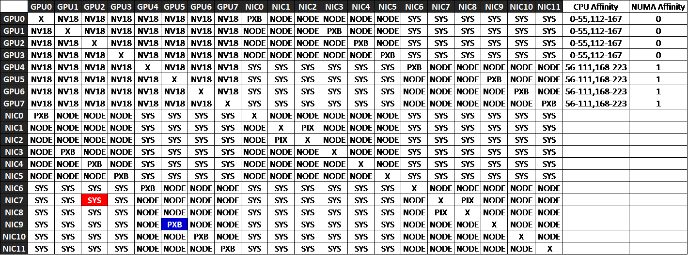
The nvidia-smi topo -m command displays the interconnect topology between GPUs, NICs, and CPUs in the system. The output is shown as a matrix where rows and columns represent devices, and each cell indicates the connection type (or “distance”) between them. These connection types reveal how traffic flows across PCIe switches, host bridges, and CPU sockets, helping identify which GPU–NIC pairings deliver the best performance.
| X | Same device (diagonal of the matrix) |
| PIX | Single PCIe switch or bridge. Shortest Path Fastest communication |
| PXB | Multiple PCIe bridges within the same root complex (NUMA node), but without traversing the PCIe Host Bridge. Slightly longer path and latency. |
| PHB | Crosses a PCIe Host Bridge (attached to CPU). May cross CPU boundaries. Lower performance. |
| SYS | Crosses multiple PCIe Host Bridges within the same NUMA node. More latency. |
| NODE | Crosses NUMA nodes, traversing QPI/UPI interconnects between CPU sockets. Slowest path — avoid for RDMA or latency-sensitive traffic. |
For RDMA traffic, choose PXB or PIX paths for GPU↔NIC pairs to keep communication within the same NUMA domain and PCIe Host Bridge. Avoid SYS or NODE paths whenever possible, as they add unnecessary latency and reduce bandwidth efficiency.
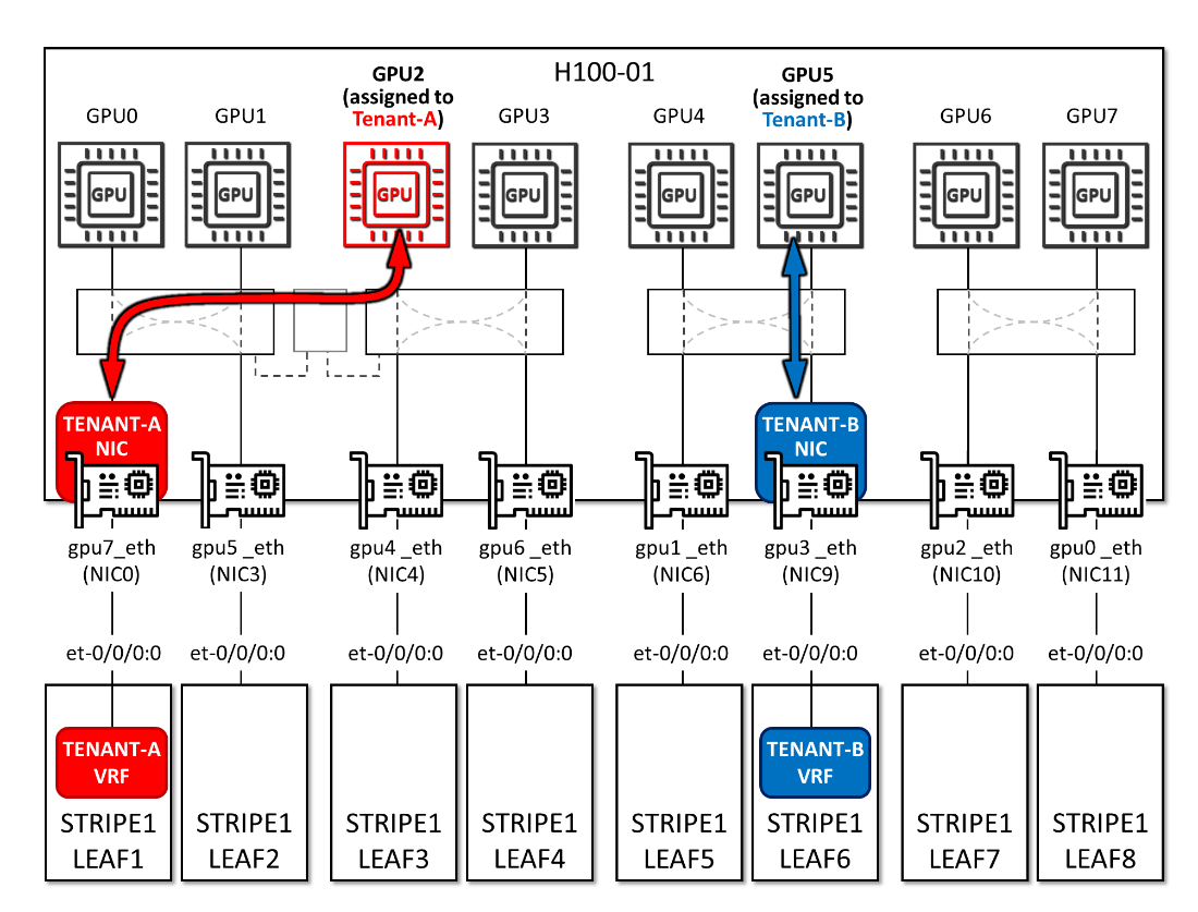
As an example, consider a case where GPU2 and NIC0 are assigned to Tenant‑A, and GPU5 and NIC9 are assigned to Tenant‑B, as shown in Figure below. The nvidia-smi topo -m output in Figure ## indicates that traffic from GPU2→NIC0 must traverse multiple PCIe host bridges and cross NUMA domains, resulting in degraded performance for Tenant‑A. In contrast, GPU5→NIC9 communicates through multiple PCIe bridges within the same root complex, avoiding CPU traversal and maintaining better performance for Tenant‑B.
Figure 61. Tenants GPU and NIC assignment example