Appendix C – IPv6 Overlay with Static Addresses Over IPv6 Underlay Fabric Implementation
This section outlines the configuration components for an IPv6 underlay and IPv6 overlay deployment.
Control Plane Implementation with IPv6 Underlay and IPv6 Overlay
This model provides an IPv6 transport underlay and IPv6 EVPN/VXLAN transport in the overlay that can support both IPv4 and IPv6 devices communicating across the fabric. This model aligns with traditional IP fabric designs, where interface addressing is fully controlled and visible, and neighbor relationships are explicitly defined, while also supporting both IPv4-only and IPv6 only end devices.
The interfaces between leaf and spine nodes are configured with explicit /127 IPv6 addresses assigned from a pool of IPv6 addresses reserved for the underlay. These addresses can be global or site local routable IPv6 addresses. Each device on the point-to-point link is configured with one of the two usable IPv6 addresses in the corresponding /127 subnet. This allows efficient address assignments for the point-to-point links between leaf and spine nodes. All leaf and spine nodes are also configured with IPv6 addresses on the loopback interface (lo0.0).
The underlay EBGP sessions are set up between the leaf and spine nodes, by explicitly configuring each neighbor, using the /127 IPv6 addresses assigned between them.
The EBGP configuration for this model includes each neighbor’s IPv6 address and Autonomous System (AS) number, the local Autonomous System (AS) number, and the export policy that allows the advertisement of routes to reach all the leaf and spine nodes in the fabric. These routes are standard IPv6 unicast advertising the IPv6 addresses assigned to the loopback interface (lo0.0).
The overlay EBGP sessions are also set up by explicitly configuring each neighbor, using the IPv6 addresses of the loopback interfaces advertised by the underlay EBGP sessions, and are also established between the leaf and spine nodes.
The leaf nodes act as VTEPs, and exchange EVPN Type 5 routes advertising the IPv4 prefixes or IPv6 prefixes assigned to the links between the GPU servers and the leaf nodes.
Example:
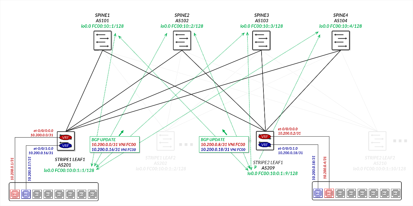
Consider the example depicted in Figure 58.
For the underlay, STRIPE1 LEAF 1 in AS 201 establishes an EBGP session with SPINE 1 in AS 101 over the directly connected IPv6 point-to-point link FC00:0:2:1::2/127 <=> FC00:0:2:1::1/127. Similarly, STRIPE2 LEAF 1 in AS 209 establishes an EBGP session with SPINE 1 over the link FC00:0:2:9::2/127 <=> FC00:0:2:9::1/127.
Figure 58: IPv6 Underlay and IPv6 Overlay Example
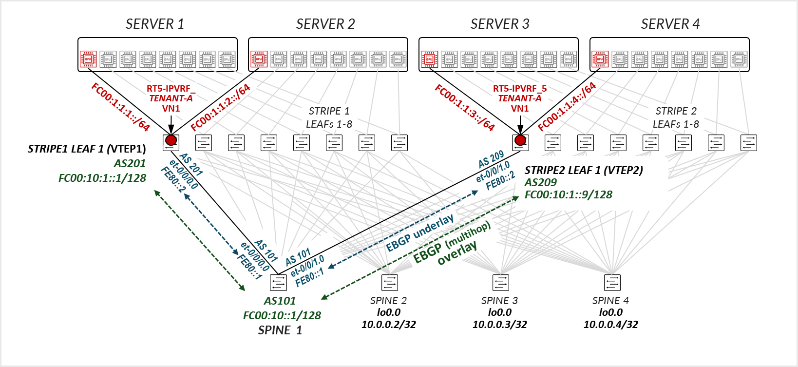
These sessions exchange IPv6 unicast routes advertising the address of the loopback interface (lo0.0) of STRIPE1 LEAF 1 (FC00:10::1:1), STRIPE2 LEAF 1 (FC00:10::1:9) and SPINE 1 (FC00:10::1).
Although it is not shown in the diagram, STRIPE1 LEAF 1 and STRIPE2 LEAF 1 will also establish EBGP sessions with SPINE 2, SPINE 3, and SPINE 4 to ensure multiple paths are available for traffic.EBGP sessions are established between the leaf nodes and SPINE 1 using their loopback addresses (FC00:10::1:1, FC00:10::1:9, and FC00:10::1 respectively).
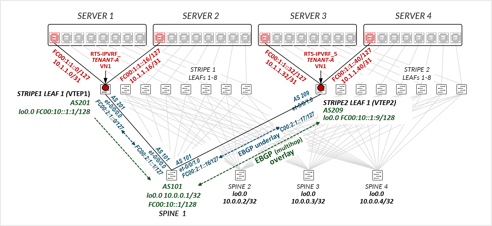
The leaf nodes acting as VTEP advertise the links connecting the GPU servers and leaf nodes which in the example are configured with /31 IPv4 and /127 IPv6 addresses.
The GPU servers and leaf nodes links are shown here with both IPv4 and IPv6 for demonstration purposes. It is not a requirement. The customer can choose which network layer address scheme to use.
The prefixes on the GPU servers and leaf nodes links are advertised using EVPN type 5 routes.
For example, STRIPE1 LEAF 1 advertises routes to the IPv4 and IPv6 addresses on the links connecting SERVER 1 GPU1 (10.1.1.0/31 and FC00:10:1:1::0/127 respectively) and SERVER 2 GPU1 to STRIPE1 LEAF 1 (10.1.1.16/31 and FC00:10:1:1::16/127 respectively).
Similarly, STRIPE2 LEAF 1 advertises router to the IPv4 addresses on the links connecting SERVER 3 GPU1 (10.1.1.32/31 and FC00:10:1:1::32/127 respectively) and SERVER 4 GPU1 to STRIPE1 LEAF 1 (10.1.1.40/31 and FC00:10:1:1::40/127 respectively).
Assuming all four GPUs in the example belong to the same tenant, their associated interfaces are mapped to the same VRF (RT5-IP-VRF_TENANT-1).
RT5-IP-VRF_TENANT-1 is configured on both STRIPE1 LEAF 1 and STRIPE2 LEAF 1 with the same VXLAN Network Identifier (VNI) and route targets. STRIPE1 LEAF 1 advertises the prefixes 10.1.1.0/31 and 10.1.1.16/31 (or their equivalent IPv6 prefixes) to SPINE 1 as EVPN Route Type 5, with its own loopback (10.0.1.1) as the next-hop VTEP. In the same way, STRIPE2 LEAF 1 advertises 10.1.1.32/31 and 10.1.1.40/31 (or their equivalent IPv6 prefixes) with 10.0.1.9 as the next-hop.
When SERVER 1 GPU1 sends traffic to SERVER 3 GPU1, the destination addresses 10.1.1.32 for example, is found in the VRF routing table on STRIPE1 LEAF 1 (Tenant-1.inet.0). The route points to STRIPE2 LEAF 1 (VTEP at 10.0.1.9) as the protocol next-hop (which is resolved to the addresses of the spine nodes). The route also specifies VNI 1 as the VXLAN encapsulation ID. The packet is encapsulated with the VXLAN header and tunneled across the fabric to its destination.
Spine Nodes to Leaf Connections
The interfaces between the leaf and spine nodes do not require explicitly configured IP addresses and are configured as untagged interfaces with only family inet and family inet6 to enable processing of IPv4 and IPv6 traffic as shown in Figure 59.
Figure 59: IPv6 underlay and IPv6 overlay configuration example
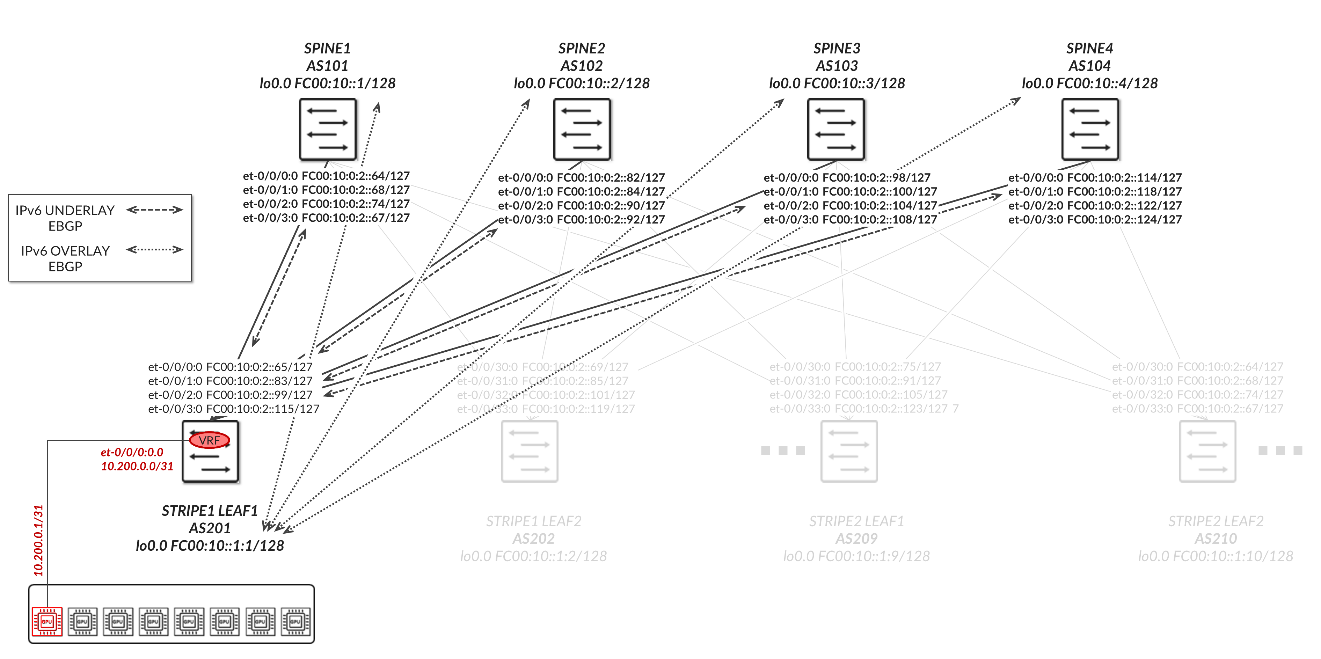
The interfaces between the leaf and spine nodes are configured with /127 addresses as shown in Table 74.
Table 74. IPv6 Address Assignments for Leaf-to-Spine Interfaces (/127 Subnetting)
| LEAF NODE INTERFACE | LEAF NODE IPv6 ADDRESS | SPINE NODE INTERFACE | SPINE IPv6 ADDRESS |
|---|---|---|---|
| Stripe 1 Leaf 1 - et-0/0/30:0 | FC00:10:0:2::65/127 | Spine 1 – et-0/0/0:0 | FC00:10:0:2::64/31 |
| Stripe 1 Leaf 1 - et-0/0/31:0 | FC00:10:0:2::83/127 | Spine 2 – et-0/0/1:0 | FC00:10:0:2::82/127 |
| Stripe 1 Leaf 1 - et-0/0/32:0 | FC00:10:0:2::99/127 | Spine 3 – et-0/0/2:0 | FC00:10:0:2::98/127 |
| Stripe 1 Leaf 1 - et-0/0/33:0 | FC00:10:0:2::155/127 | Spine 4 – et-0/0/3:0 | FC00:10:0:2::114/127 |
| Stripe 1 Leaf 5 - et-0/0/30:0 | FC00:10:0:2::69/127 | Spine 1 – et-0/0/0:0 | FC00:10:0:2::68/127 |
| Stripe 1 Leaf 2 - et-0/0/31:0 | FC00:10:0:2::85/127 | Spine 2 – et-0/0/1:0 | FC00:10:0:2::.84/127 |
| Stripe 1 Leaf 2 - et-0/0/32:0 | FC00:10:0:2::101/127 | Spine 3 – et-0/0/2:0 | FC00:10:0:2::100/127 |
| Stripe 1 Leaf 2 - et-0/0/33:0 | FC00:10:0:2::119/127 | Spine 4 – et-0/0/3:0 | FC00:10:0:2::118/127 |
|
. . . |
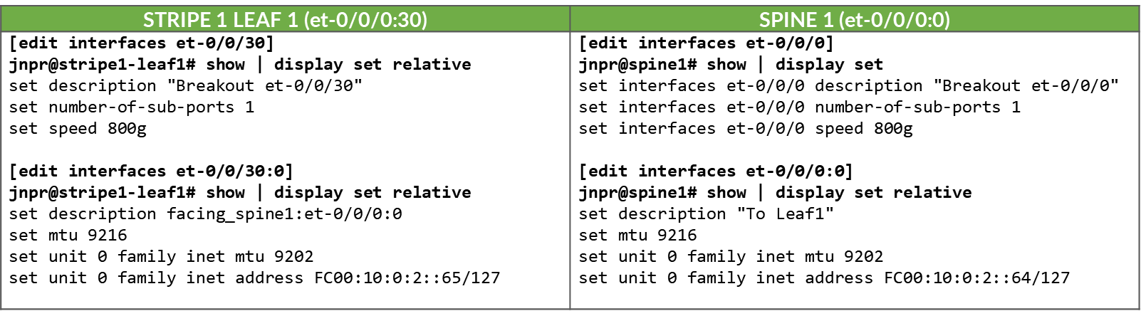
These interfaces are configured as untagged interfaces, with family inet6 and static IPv6 addresses, as shown in the example for the link between Stripe 1 Leaf 1 and Spine 1 below:
Table 75. Example Junos Configuration for Leaf-Spine IPv6 Interface (/127 Subnet)
The loopback and Autonomous System numbers for all devices in the fabric are included in Table 76.
Table 76. Loopback IPv6 Addresses and Autonomous System Numbers
| LEAF NODE INTERFACE | lo0.0 IPv6 ADDRESS | Local AS # |
|---|---|---|
| Stripe 1 Leaf 1 | FC00:10:0:1::1/128 | 201 |
| Stripe 1 Leaf 2 | FC00:10:0:1::2/128 | 202 |
| Stripe 1 Leaf 3 | FC00:10:0:1::3/128 | 203 |
| Stripe 1 Leaf 4 | FC00:10:0:1::4/128 | 204 |
| Stripe 1 Leaf 5 | FC00:10:0:1::5/128 | 205 |
| Stripe 1 Leaf 6 | FC00:10:0:1::6/128 | 206 |
| Stripe 1 Leaf 7 | FC00:10:0:1::7/128 | 207 |
| Stripe 1 Leaf 8 | FC00:10:0:1::8/128 | 208 |
| Stripe 2 Leaf 1 | FC00:10:0:1::9/128 | 209 |
| Stripe 2 Leaf 2 | FC00:10:0:1::10/128 | 210 |
|
. . . |
||
| SPINE1 | FC00:10::1/128 | 101 |
| SPINE2 | FC00:10::2/128 | 102 |
| SPINE3 | FC00:10::3/128 | 103 |
| SPINE4 | FC00:10::4/128 | 104 |
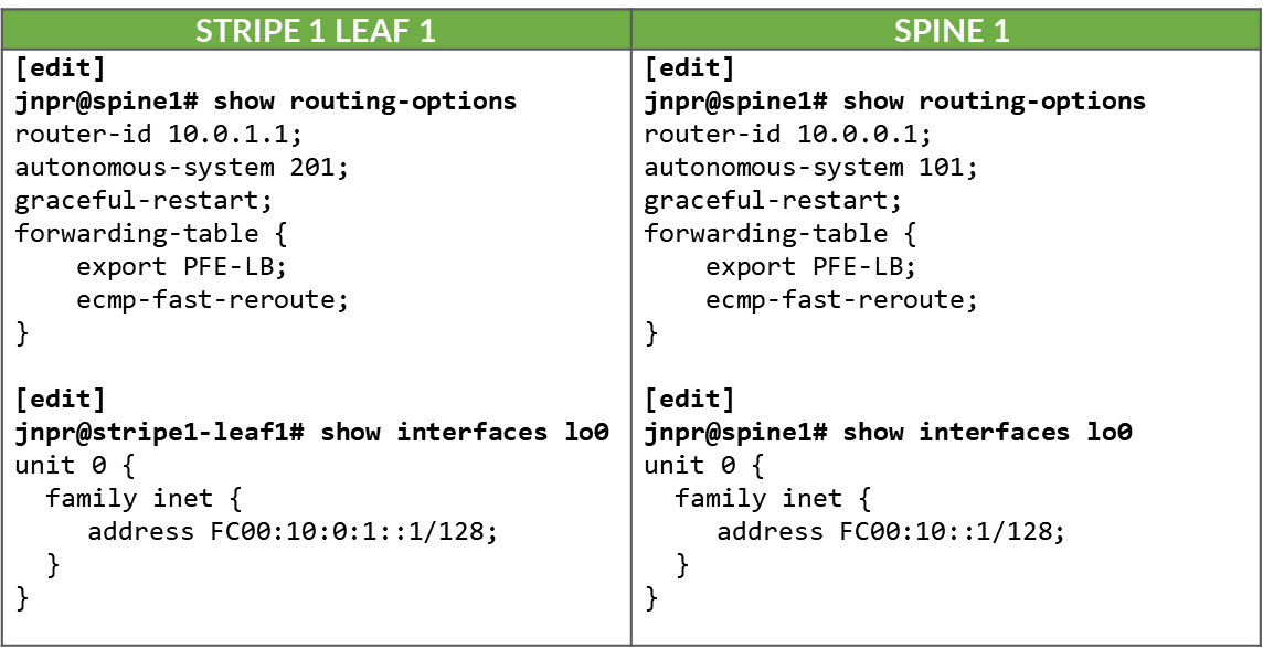
Table 77. Example Junos Configuration for IPv6 Loopback Interfaces and Routing Options
GPU Backend Fabric Underlay with IPv6
The underlay EBGP sessions are configured between the leaf and spine nodes using the IP addresses of the directly connected links, as shown in the example between Stripe1 Leaf 1 and the spine nodes below:
Table 78. IPv6 EBGP Underlay Configuration Example: Stripe 1 Leaf 1 to Spine 1

Table 79. IPv6 EBGP Underlay Configuration Example: Stripe 1 Leaf 1 to Spine 2
All the BGP sessions are configured with multipath multiple-as, which allows multiple paths (to the same destination) with different AS paths to be considered for ECMP (Equal-Cost Multi-Path) routing, and with BFD to improve convergence in case of failures.
To control the propagation of routes, export policies are applied to
these EBGP sessions as shown in the example in Table 80.
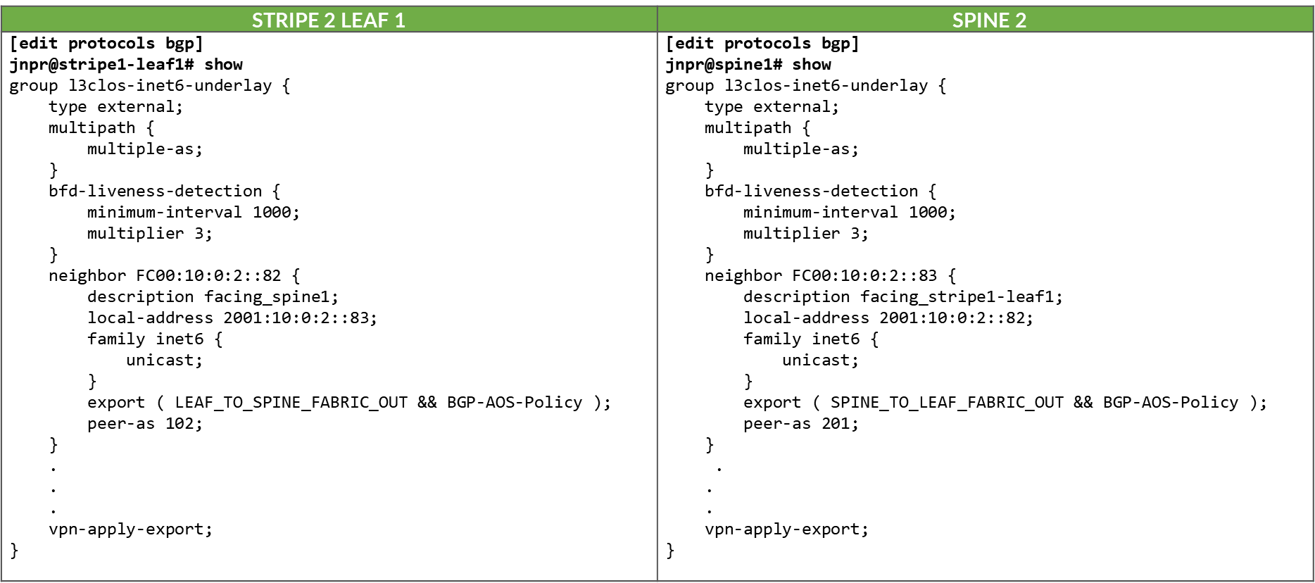
Table 80. Export policy example to advertise IPv6 routes over IPv6 BGP Underlay
These policies ensure loopback reachability is advertised cleanly and without the risk of route loops.
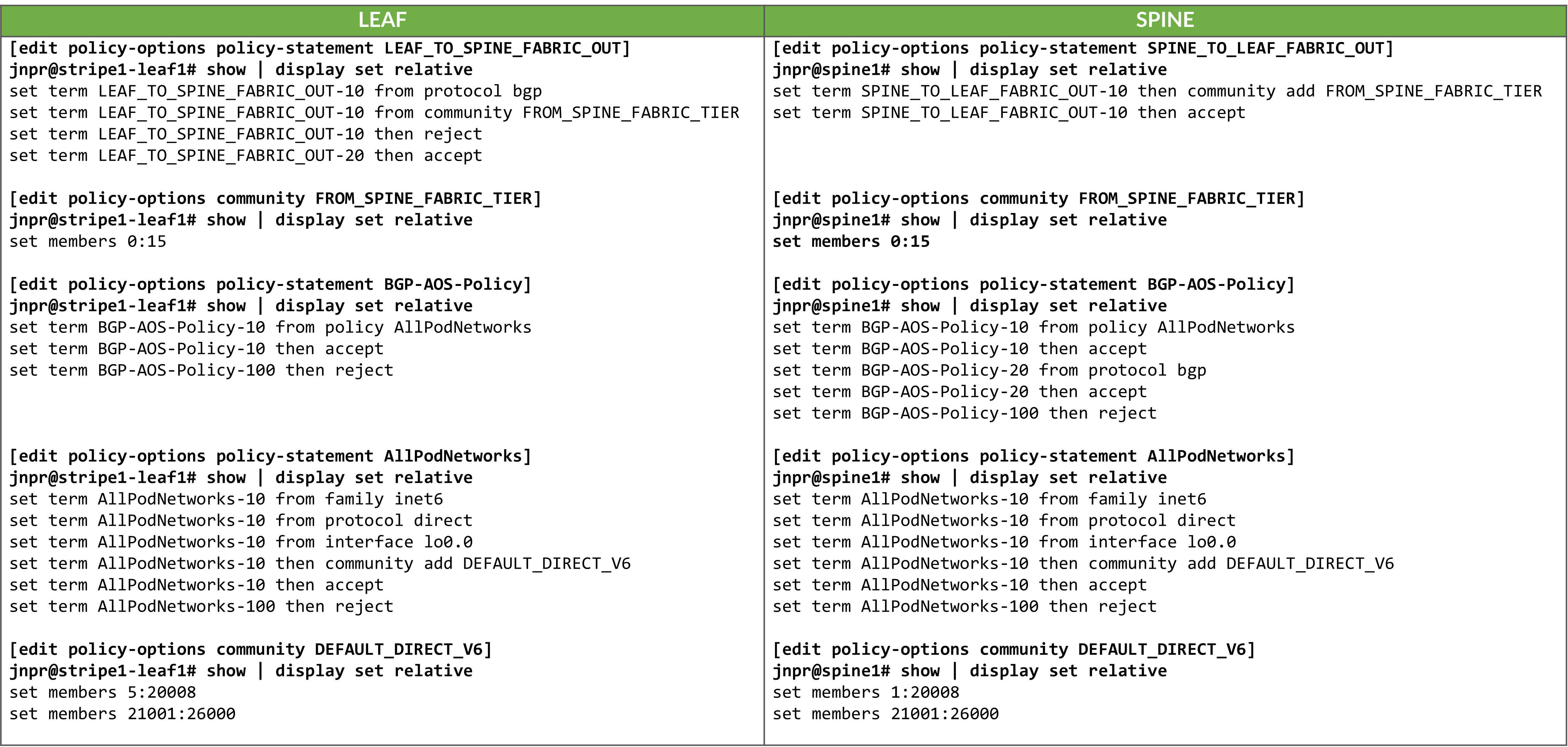
On the spine nodes, routes are exported only if they are accepted by both the SPINE_TO_LEAF_FABRIC_OUT and BGP-AOS-Policy export policies.
- The SPINE_TO_LEAF_FABRIC_OUT policy has no match conditions and accepts all routes unconditionally, tagging them with the FROM_SPINE_FABRIC_TIER community (0:15).
- The BGP-AOS-Policy accepts BGP-learned routes as well as any routes accepted by the nested AllPodNetworks policy.
- The AllPodNetworks policy, in turn, matches directly connected IPv6 routes and tags them with the DEFAULT_DIRECT_V4 community (1:20007 and 21001:26000 on Spine1).
As a result, each spine advertises both its directly connected routes (including its loopback interface) and any routes it has received from other leaf nodes.
Example:
jnpr@spine1>  show route advertising-protocol bgp FC00:10:0:2::65 | match /32
* FC00:10::1/128                        Self       I
* FC00:10:0:1::2/128                    Self       202 I
* FC00:10:0:1::3/128                    Self       203 I
---more---
jnpr@spine1> show route advertising-protocol bgp FC00:10:0:2::65 FC00:10::0/128 extensive
inet6.0: 36 destinations, 40 routes (36 active, 0 holddown, 0 hidden)
Restart Complete
* FC00:10::0/128 (1 entry, 1 announced)
 BGP group l3clos-inet6-underlay type External
     Nexthop: Self
     AS path: [101] I
     Communities: 0:15 1:20008 21001:26000
jnpr@spine1> show route advertising-protocol bgp FC00:10:0:2::65 FC00:10:0:1::2/128 extensive
inet6.0: 85 destinations, 169 routes (85 active, 0 holddown, 0 hidden)
Restart Complete
* FC00:10:0:1::2/128 (1 entry, 1 announced)
 BGP group l3clos-inet6-underlay type External
     AS path: [101] 202 I
     Communities: 0:15 5:20008 21001:26000
On the leaf nodes, routes are exported only if they are accepted by both the LEAF_TO_SPINE_FABRIC_OUT and BGP-AOS-Policy export policies.
The LEAF_TO_SPINE_FABRIC_OUT policy accepts all routes except those learned via BGP that are tagged with the FROM_SPINE_FABRIC_TIER community (0:15). These routes are explicitly rejected to prevent re-advertisement of spine-learned routes back into the spine layer. As described earlier, spine nodes tag all routes they advertise to leaf nodes with this community to facilitate this filtering logic.
The BGP-AOS-Policy accepts all routes allowed by the nested AllPodNetworks policy, which matches directly connected IPv6 routes and tags them with the DEFAULT_DIRECT_V4 community (5:20007 and 21001:26000 for Stripe1-Leaf1).
As a result, leaf nodes will advertise only their directly connected interface routes—including their loopback interfaces, to the spines.
jnpr@stripe1-leaf1>  show route advertising-protocol bgp FC00:10:0:2::64 | match /32
* FC00:10:0:1::1/128      Self                                    I
jnpr@stripe1-leaf1>  show route advertising-protocol bgp FC00:10:0:2::64 FC00:10:0:1::1/128  extensive
inet6.0: 48 destinations, 257 routes (48 active, 0 holddown, 0 hidden)
Restart Complete
* FC00:10:0:1::1/128  (1 entry, 1 announced)
 BGP group l3clos-inet6-underlay  type External
     Nexthop: Self
     AS path: [201] I
     Communities: 5:20007 21001:26000
GPU Backend Fabric Overlay with IPv6
The overlay EBGP sessions are configured between the leaf and spine nodes using the IPv4 addresses of the loopback interfaces, as shown in the example between Stripe1 Leaf 1/Stripe 2 Leaf 1 and Spine 1.
Table 81. IPv6 EVPN Overlay EBGP Configuration Example: Stripe 1 Leaf 1 to Spine 1

Table 82. IPv6 EVPN Overlay EBGP Configuration Example: Stripe 2 Leaf 1 to Spine 1
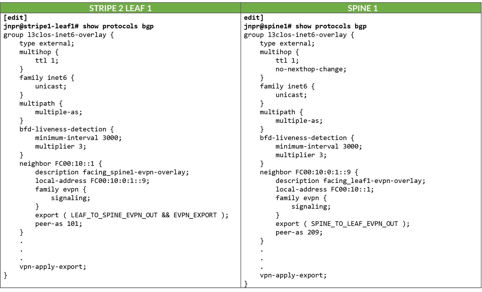
The overlay BGP sessions use family evpn signaling to enable
EVPN route exchange. The multihop ttl 1 statement
allows EBGP sessions to be established between the loopback
interfaces.
As with the underlay BGP sessions, these sessions are configured
with multipath multiple-as, allowing multiple EVPN
paths with different AS paths to be considered for ECMP (Equal-Cost
Multi-Path) routing. BFD (Bidirectional Forwarding Detection) is
also enabled to improve convergence time in case of failures.
The no-nexthop-change knob on the spine nodes is
used to preserve the original next-hop address, which is critical
in EVPN for ensuring that the remote VTEP can be reached directly.
The vpn-apply-export statement is included to ensure
that the export policies are evaluated for VPN address families,
such as EVPN, allowing fine-grained control over which routes are
advertised to each peer.
To control the propagation of routes, export policies are applied to these EBGP sessions as shown in the example in Table 83.
Table 83. Export Policy example to advertise EVPN routes over IPv6 BGP Overlay
.png)
These policies are simpler in structure and are intended to enable end-to-end EVPN reachability between tenant GPUs, while preventing route loops within the overlay.
Routes will only be advertised if EVPN routing-instances have been created. Example:
Table 84. EVPN Routing-Instances for a single tenant example
across different leaf nodes..png)
On the spine nodes, routes are exported if they are accepted by the SPINE_TO_LEAF_EVPN_OUT policy.
- The SPINE_TO_LEAF_EVPN_OUT policy has no match conditions and accepts all routes. It tags each exported route with the FROM_SPINE_EVPN_TIER community (0:14).
As a result, the spine nodes export EVPN routes received from one leaf to all other leaf nodes, allowing tenant-to-tenant communication across the fabric.
Example:
jnpr@spine1>  show route advertising-protocol bgp FC00:10:0:1::1 | match 5:10.*2001.*31
  5:10.0.1.2:2001::0::10.200.0.2::31/248
  5:10.0.1.2:2001::0::10.200.0.34::31/248
  5:10.0.1.9:2001::0::10.200.1.0::31/248
  5:10.0.1.9:2001::0::10.200.1.32::31/248
  5:10.0.1.10:2001::0::10.200.1.2::31/248
  5:10.0.1.10:2001::0::10.200.1.34::31/248
jnpr@spine1>  show route advertising-protocol bgp FC00:10:0:1::1 match-prefix 5:10.0.1.9:2001::0::10.200.1.0::31/248
bgp.evpn.0: 378 destinations, 378 routes (378 active, 0 holddown, 0 hidden)
Restart Complete
  Prefix                                        Nexthop        MED  Lclpref    AS path
  5:10.0.1.9:2001::0::10.200.1.0::31/248   * FC00:10:0:1::9                     209 I
On the leaf nodes, routes are exported if they are accepted by both the LEAF_TO_SPINE_EVPN_OUT and EVPN_EXPORT policies.
- The LEAF_TO_SPINE_EVPN_OUT policy rejects any BGP-learned routes that carry the FROM_SPINE_EVPN_TIER community (0:14). These routes are explicitly rejected to prevent re-advertisement of spine-learned routes back into the spine layer. As described earlier, spine nodes tag all routes they advertise to leaf nodes with this community to facilitate this filtering logic.
- The EVPN_EXPORT policy accepts all routes without additional conditions.
As a result, the leaf nodes export only locally originated EVPN routes for the directly connected interfaces between GPU servers and the leaf nodes. These routes are part of the tenant routing instances and are required to establish reachability between GPUs belonging to the same tenant.
jnpr@stripe1-leaf1> show route advertising-protocol bgp FC00:10::1 table Tenant-1
Tenant-1.evpn.0: 8 destinations, 20 routes (8 active, 0 holddown, 0 hidden)
Restart Complete
  Prefix                        Nexthop         MED     Lclpref         AS path
  5:10.0.1.1:2001::0::10.200.0.0::31/248
*                               Self                    I
  5:10.0.1.1:2001::0::10.200.0.16::31/248
*                               Self                    I
jnpr@stripe1-leaf1> show route advertising-protocol bgp FC00:10::1 table Tenant-2
Tenant-2.evpn.0: 8 destinations, 20 routes (8 active, 0 holddown, 0 hidden)
Restart Complete
  Prefix                        Nexthop MED     Lclpref    AS path
  5:10.0.1.1:2002::0::10.200.0.2::31/248
*                               Self                    I
  5:10.0.1.1:2002::0::10.200.0.18::31/248
*                               Self                    I
Configuration and Verification Example
Consider the following scenario where Tenant-1 has been assigned GPU 0 on Server 1 and GPU1 on Server 2, and Tenant-2 has been assigned GPU 0 on Server 2 and GPU1 on Server 1 as shown in Figure 60.
Figure 60: Overlay example with two tenants
Both Stripe 1 Leaf 1 and Leaf 2 have been configured for Tenant-1 and Tenant-2 as shown below:
Table 85. EVPN Routing-Instance for Tenant-1 and Tenant-2 Across Stripe 1 and Stripe 2
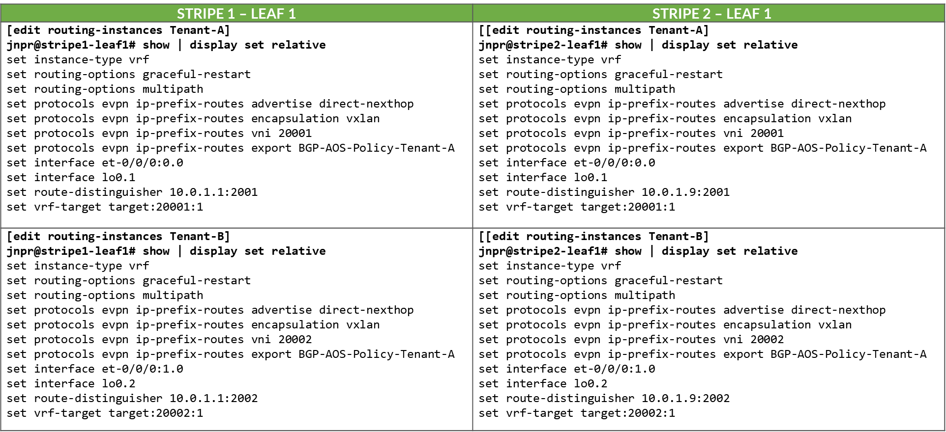
Table 86. Policies Examples for Tenant-1 and Tenant-2 Across Stripe 1 and Stripe 2
.png)
The routing instances create separate routing spaces for the two tenants, providing full route and traffic isolation across the EVPN/VXLAN fabric. Each routing instance has been configured with the following key elements:
- Interfaces:
The interfaces listed under each tenant VRF (e.g. et-0/0/0:0.0 and et-0/0/1:0.0) are explicitly added to the corresponding routing table. By placing these interfaces under the VRF, all routing decisions and traffic forwarding associated with them are isolated from other tenants and from the global routing table. Assigning an interface that connects a particular GPU to the leaf node effectively maps that GPU to a specific tenant, isolating it from GPUs assigned to other tenants.
- Route-distinguisher (RD):
10.0.1.1:2001 and 10.0.1.1:2002 uniquely identify EVPN routes from Tenant-1 and Tenant-2, respectively. Even if both tenants use overlapping IP prefixes, the RD ensures their routes remain distinct in the BGP control plane. Although the GPU to leaf links use unique /32 prefixes, an RD is still required to advertise these routes over EVPN.
- Route target (RT) community:
VRF targets 20001:1 and 20002:1 control which routes are exported from and imported into each tenant routing table. These values determine which routes are shared between VRFs that belong to the same tenant across the fabric and are essential for enabling fabric-wide tenant connectivity, for example, when a tenant has GPUs assigned to multiple servers across different stripes.
-
Protocols evpn parameters:
- The ip-prefix-routes controls how IP Prefix Routes (EVPN Type 5 routes) are advertised.
- The advertise direct-nexthop enables the leaf node to send IP prefix information using EVPN pure Type 5 routes, which includes a router MAC extended community. These routes include a Router MAC extended community, which allows the remote VTEP to resolve the next-hop MAC address without relying on Type 2 routes.
- The encapsulation vxlan indicates that the payload traffic for this tenant will be encapsulated using VXLAN. The same type of encapsulation must be used end to end.
- The VXLAN Network Identifier (VNI) acts as the encapsulation tag for traffic sent across the EVPN/VXLAN fabric. When EVPN Type 5 (IP Prefix) routes are advertised, the associated VNI is included in the BGP update. This ensures that remote VTEPs can identify the correct VXLAN segment for returning traffic to the tenant’s VRF.
Unlike traditional use cases where a VNI maps to a single Layer 2 segment, in EVPN Type 5 the VNI represents the tenant-wide Layer 3 routing domain. All point-to-point subnets, such as the /32 links between GPU servers and the leaf, that belong to the same VRF are advertised with the same VNI.
In this configuration, VNIs 20001 and 20002 are mapped to the Tenant-1 and Tenant-2 VRFs, respectively. All traffic destined for interfaces in Tenant-1 will be forwarded using VNI 20001, and all traffic for Tenant-2 will use VNI 20002.
Notice that the same VNI for a specific tenant is configured on both Stripe1-Leaf1 and Stripe2-Leaf1.
- Export Policy Logic
EVPN Type 5 routes from Tenant-1 are exported if they are accepted by the BGP-AOS-Policy-Tenant-1 export policy, which references a nested policy named AllPodNetworks-Tenant-1 (and the equivalent policies for Tenant-2)
- Policy BGP-AOS-Policy-Tenant-1 controls which prefixes from this VRFs are allowed to be advertised into EVPN. It accepts any route that is permitted by the AllPodNetworks-Tenant-1 policy and explicitly rejects all other routes.
- Policy AllPodNetworks-Tenant-1 accepts directly connected IPv4 routes (family inet, protocol direct) that are part of the Tenant-1 VRF. It tags these routes with the TENANT-1_COMMUNITY_V4 (5:20007 21002:26000 ) community before accepting them. All other routes are rejected.
As a result, only the directly connected IPv4 routes from the Tenant-1 (/32 links between GPU servers and the leaf) are exported as EVPN Type 5 routes.
To verify the interface assignments to the different tenants, use show interfaces
routing-instance <tenant-name> terse.
jnpr@stripe1-leaf1> show interfaces routing-instance Tenant-1 terse
Interface               Admin   Link    Proto           Local                 Remote
et-0/0/0:0.0            up      up      inet            10.200.0.0/31
                        multiservice
lo0.1                   up      up      inet            192.168.11.1        --> 0/0
jnpr@stripe1-leaf1> show interfaces routing-instance Tenant-2 terse
Interface               Admin   Link    Proto           Local                 Remote
et-0/0/1:0.0            up      up      inet            10.200.0.16/31
                        multiservice
lo0.1                   up      up      inet            192.168.11.2        --> 0/0
jnpr@stripe1-leaf2> show interfaces routing-instance Tenant-1 terse
Interface               Admin   Link    Proto           Local                 Remote
et-0/0/0:0.0            up      up      inet            10.200.0.2/31
                        multiservice
lo0.1                   up      up      inet            192.168.12.1        --> 0/0
jnpr@stripe1-leaf2> show interfaces routing-instance Tenant-2 terse
Interface               Admin   Link    Proto           Local                 Remote
et-0/0/1:0.0            up      up      inet            10.200.0.18/31
                        multiservice
lo0.1                   up      up      inet            192.168.12.2        --> 0/0
You can also check the direct routes installed to the correspondent routing table:
jnpr@stripe1-leaf1> show route protocol direct table Tenant-1.inet.0
Tenant-1.inet.0: 14 destinations, 14 routes (14 active, 0 holddown, 0 hidden)
Restart Complete
@ = Routing Use Only, # = Forwarding Use Only
+ = Active Route, - = Last Active, * = Both
10.200.0.0/31           *[Direct/0] 02:24:29
                         >  via et-0/0/12:0.0
192.168.11.1/32         *[Direct/0] 02:16:52
                         >  via lo0.1
jnpr@stripe1-leaf1> show route protocol direct table Tenant-2.inet.0
Tenant-2.inet.0: 14 destinations, 14 routes (14 active, 0 holddown, 0 hidden)
Restart Complete
@ = Routing Use Only, # = Forwarding Use Only
+ = Active Route, - = Last Active, * = Both
10.200.0.16/31          *[Direct/0] 02:24:29
                         >  via et-0/0/12:0.0
192.168.11.1/32         *[Direct/0] 02:16:52
                         >  via lo0.2
jnpr@stripe1-leaf2> show route protocol direct table Tenant-1.inet.0
tenant-1.inet.0: 14 destinations, 14 routes (14 active, 0 holddown, 0 hidden)
Restart Complete
@ = Routing Use Only, # = Forwarding Use Only
+ = Active Route, - = Last Active, * = Both
10.200.0.2/31           *[Direct/0] 1d 17:42:33
                        >  via et-0/0/2:0.0
192.168.12.1/32         *[Direct/0] 02:16:52
                         >  via lo0.1
jnpr@stripe1-leaf2> show route protocol direct table Tenant-2.inet.0
tenant-1.inet.0: 14 destinations, 14 routes (14 active, 0 holddown, 0 hidden)
Restart Complete
@ = Routing Use Only, # = Forwarding Use Only
+ = Active Route, - = Last Active, * = Both
10.200.0.18/31          *[Direct/0] 1d 17:42:33
                        >  via et-0/0/3:0.0
192.168.12.1/32         *[Direct/0] 02:16:52
                         >  via lo0.2
To verify evpn l3 contexts including encapsulation, VNI, router MAC address, use
show evpn l3-context
Use <tenant-name> extensive for more details.
jnpr@stripe1-leaf1> show evpn l3-context
L3 context              Type    Adv             Encap   VNI/Label       Router MAC/GW intf dt4-sid                         dt6-sid                  dt46-sid
Tenant-1                                Cfg     Direct          VXLAN   20001           9c:5a:80:c1:b3:06
Tenant-2                                Cfg     Direct          VXLAN   20002           9c:5a:80:c1:b3:06
jnpr@stripe1-leaf1> show evpn l3-context
L3 context              Type    Adv             Encap   VNI/Label       Router MAC/GW intf dt4-sid                         dt6-sid                  dt46-sid
Tenant-1                                Cfg     Direct          VXLAN   20001           58:86:70:79:df:db
Tenant-2                                Cfg     Direct          VXLAN   20002           58:86:70:79:df:db
jnpr@stripe1-leaf1> show evpn l3-context Tenant-1 extensive
L3 context: Tenant-1
  Type: Configured
  Advertisement mode: Direct nexthop, Router MAC: 9c:5a:80:c1:b3:06
  Encapsulation: VXLAN, VNI: 20001
  IPv6 source VTEP address: FC00:10:0:1::1
  IP->EVPN export policy: BGP-AOS-Policy-Tenant-1
  Flags: 0xc209 <Configured IRB-MAC ROUTING RT-INSTANCE-TARGET-IMPORT-POLICY RT-INSTANCE-TARGET-EXPORT-POLICY>
  Change flags: 0x20000 <VXLAN-VNI-Update-RTT-OPQ>
  Composite nexthop support: Disabled
  Route Distinguisher: 10.0.1.1:2001
  Reference count: 5
  EVPN Multicast Routing mode: CRB
jnpr@stripe1-leaf1> show evpn l3-context Tenant-2 extensive
L3 context: Tenant-2
  Type: Configured
  Advertisement mode: Direct nexthop, Router MAC: 9c:5a:80:c1:b3:06
  Encapsulation: VXLAN, VNI: 20002
  IPv6 source VTEP address: FC00:10:0:1::1
  IP->EVPN export policy: BGP-AOS-Policy-Tenant-2
  Flags: 0xc209 <Configured IRB-MAC ROUTING RT-INSTANCE-TARGET-IMPORT-POLICY RT-INSTANCE-TARGET-EXPORT-POLICY>
  Change flags: 0x20000 <VXLAN-VNI-Update-RTT-OPQ>
  Composite nexthop support: Disabled
  Route Distinguisher: 10.0.1.1:2002
  Reference count: 5
  EVPN Multicast Routing mode: CRB
jnpr@stripe1-leaf2> show evpn l3-context Tenant-1 extensive
L3 context: Tenant-1
  Type: Configured
  Advertisement mode: Direct nexthop, Router MAC: 58:86:70:79:df:db
  Encapsulation: VXLAN, VNI: 20001
  IPv6 source VTEP address: FC00:10:0:1::2
  IP->EVPN export policy: BGP-AOS-Policy-Tenant-1
  Flags: 0xc209 <Configured IRB-MAC ROUTING RT-INSTANCE-TARGET-IMPORT-POLICY RT-INSTANCE-TARGET-EXPORT-POLICY>
  Change flags: 0x20000 <VXLAN-VNI-Update-RTT-OPQ>
  Composite nexthop support: Disabled
  Route Distinguisher: 10.0.1.2:2001
  Reference count: 5
  EVPN Multicast Routing mode: CRB
jnpr@stripe1-leaf2> show evpn l3-context Tenant-1 extensive
L3 context: Tenant-2
  Type: Configured
  Advertisement mode: Direct nexthop, Router MAC: 58:86:70:79:df:db
  Encapsulation: VXLAN, VNI: 20002
  IPv6 source VTEP address: FC00:10:0:1::2
  IP->EVPN export policy: BGP-AOS-Policy-Tenant-2
  Flags: 0xc209 <Configured IRB-MAC ROUTING RT-INSTANCE-TARGET-IMPORT-POLICY RT-INSTANCE-TARGET-EXPORT-POLICY>
  Change flags: 0x20000 <VXLAN-VNI-Update-RTT-OPQ>
  Composite nexthop support: Disabled
  Route Distinguisher: 10.0.1.2:2002
  Reference count: 5
  EVPN Multicast Routing mode: CRB
jnpr@stripe1-leaf1> show evpn ip-prefix-database
L3 context: Tenant-1
IPv4->EVPN Exported Prefixes
Prefix                                       EVPN route status
10.200.0.0/31                                Created
192.168.11.1/32                              Created
EVPN->IPv4 Imported Prefixes
Prefix                                       Etag
10.200.0.2/31                                0
  Route distinguisher    VNI/Label/SID           Router MAC         Nexthop/Overlay GW/ESI   Route-Status  Reject-Reason
  10.0.1.2:2001          20001                   58:86:70:79:df:db  FC00:10:0:1::2      Accepted      n/a
192.168.12.1/32                              0
  Route distinguisher    VNI/Label/SID           Router MAC         Nexthop/Overlay GW/ESI   Route-Status  Reject-Reason
  10.0.1.2:2001          20001                   58:86:70:79:df:db  FC00:10:0:1::2      Accepted      n/a
L3 context: Tenant-2
IPv4->EVPN Exported Prefixes
Prefix                                       EVPN route status
10.200.0.16/31                               Created
192.168.11.2/32                              Created
EVPN->IPv4 Imported Prefixes
Prefix                                       Etag
10.200.0.18/31                               0
  Route distinguisher    VNI/Label/SID           Router MAC         Nexthop/Overlay GW/ESI   Route-Status  Reject-Reason
  10.0.1.2:2002          20002                   58:86:70:79:df:db  10.0.1.2                  Accepted      n/a
192.168.12.2/32                              0
  Route distinguisher    VNI/Label/SID           Router MAC         Nexthop/Overlay GW/ESI   Route-Status  Reject-Reason
  10.0.1.2:2002          20002                   58:86:70:79:df:db  10.0.1.2                  Accepted      n/a
When EVPN Type 5 is used to implement L3 tenant isolation across a VXLAN fabric, multiple routing tables are instantiated on each participating leaf node. These tables are responsible for managing control-plane separation, enforcing tenant boundaries, and supporting the overlay forwarding model. Each routing instance (VRF) creates its own set of routing and forwarding tables, in addition to the global and EVPN-specific tables used for fabric-wide communication. These tables are listed in Table 87.
Table 87. Routing and Forwarding Tables for EVPN Type 5
| TABLE | DESCRIPTON |
|---|---|
| bgp.evpn.0 |
Holds EVPN route information received via BGP, including Type 5 (IP Prefix) routes and other EVPN route types. This is the control plane source for EVPN-learned routes |
| :vxlan.inet.0 |
Used internally for VXLAN tunnel resolution. Maps VTEP IP addresses to physical next-hops. |
| <tenant>.inet.0 |
The tenant-specific IPv4 unicast routing table. Contains directly connected and EVPN-imported Type 5 prefixes for that tenant. Used for routing data plane traffic. |
| <tenant>.evpn.0 | The tenant-specific EVPN table. |
When an EVPN route is received, the protocol next-hop is extracted and resolved in inet.0. The EVPN route is added to the bgp.evpn.0 table. The result is placed in :vxlan.inet.0.
The route-target community value is used to determine which tenant the route belongs to, and the route is placed in tenant.evpn.0. From there, IPv4 routes are imported into tenant.inet4.0 to be used for route lookups when traffic arrives at the interfaces belonging to the VRF.
IPv6 EBGP sessions advertising evpn routes for Tenant-1 and Tenant-2 should be established. The routes should be installed in both the bgp.evpn.0 table and the <Tenant>.inet.0 table.
jnpr@stripe1-leaf1> show bgp summary | no-more
---more---
Peer                     AS      InPkt     OutPkt    OutQ   Flaps Last Up/Dwn State|#Active/Received/Accepted/Damped...
FC00:10::1                101          5          4       0       0          18 Establ
  bgp.evpn.0: 4/4/4/0
  Tenant-1.evpn.0: 2/2/2/0
  Tenant-2.evpn.0: 2/2/2/0
FC00:10::2                102          5          4       0       0          14 Establ
  bgp.evpn.0: 0/4/4/0
  Tenant-1.evpn.0: 0/2/2/0
  Tenant-2.evpn.0: 0/2/2/0
FC00:10::3                103          5          4       0       0          10 Establ
  bgp.evpn.0: 0/4/4/0
  Tenant-1.evpn.0: 0/2/2/0
  Tenant-2.evpn.0: 0/2/2/0
FC00:10::4                104          5          4       0       0           6 Establ
  bgp.evpn.0: 0/4/4/0
  Tenant-1.evpn.0: 0/2/2/0
  Tenant-2.evpn.0: 0/2/2/0
jnpr@stripe2-leaf1> show bgp summary | no-more
---more---
Peer                     AS      InPkt     OutPkt    OutQ   Flaps Last Up/Dwn State|#Active/Received/Accepted/Damped...
FC00:10::1                101        206        199       0       0     1:29:40 Establ
  bgp.evpn.0: 4/4/4/0
  Tenant-1.evpn.0: 2/2/2/0
  Tenant-2.evpn.0: 2/2/2/0
FC00:10::2                102        206        199       0       0     1:29:25 Establ
  bgp.evpn.0: 4/4/4/0
  Tenant-1.evpn.0: 2/2/2/0
  Tenant-2.evpn.0: 2/2/2/0
FC00:10::3                103        206        199       0       0     1:29:26 Establ
  bgp.evpn.0: 4/4/4/0
  Tenant-1.evpn.0: 2/2/2/0
  Tenant-2.evpn.0: 2/2/2/0
FC00:10::4                104        207        199       0       0     1:29:39 Establ
  bgp.evpn.0: 4/4/4/0
  Tenant-1.evpn.0: 2/2/2/0
  Tenant-2.evpn.0: 2/2/2/0
To check that evpn routes are being advertised, use show route
advertising-protocol bgp <neighbor>. For a specific route, use the
match-prefix option and include the entire evpn prefix as shown in the
example below.
jnpr@stripe1-leaf1>  show route advertising-protocol bgp FC00:10::1 table Tenant | match 5:10.0.1.1:2001 | match 31/248
  5:10.0.1.1:2001::0::10.200.0.0::31/248

jnpr@stripe1-leaf1>  show route advertising-protocol bgp FC00:10::1 table Tenant | match 5:10.0.1.1:2002 | match 31/248
  5:10.0.1.1:2002::0::10.200.0.16::31/248
jnpr@stripe1-leaf2>  show route advertising-protocol bgp FC00:10::1 table Tenant | match 5:10.0.1.2:2001 | match 31/248
  5:10.0.1.2:2001::0::10.200.0.2::31/248

jnpr@stripe1-leaf2>  show route advertising-protocol bgp FC00:10::1 table Tenant | match 5:10.0.1.2:2002 | match 31/248
  5:10.0.1.2:2002::0::10.200.0.18::31/248
jnpr@ stripe1-leaf1> show route advertising-protocol bgp FC00:10::1 match-prefix  5:10.0.1.1:2001::0::10.200.0.0::31/248 table Tenant-1
Tenant-1.evpn.0: 12 destinations, 54 routes (12 active, 0 holddown, 0 hidden)
Restart Complete
  Prefix                                Nexthop              MED     Lclpref    AS path
  5:10.0.1.1:2001::0::10.200.0.0::31/248        *  Self                                    I
jnpr@ stripe1-leaf1> show route advertising-protocol bgp FC00:10::1 match-prefix  5:10.0.1.1:2002::0::10.200.0.16::31/248 table Tenant-2
Tenant-2.evpn.0: 12 destinations, 54 routes (12 active, 0 holddown, 0 hidden)
Restart Complete
  Prefix                                Nexthop              MED     Lclpref    AS path
  5:10.0.1.1:2002::0::10.200.0.16::31/248               *  Self                                    I
jnpr@stripe1-leaf2> show route advertising-protocol bgp FC00:10::1 match-prefix  5:10.0.1.2:2001::0::10.200.0.2::31/248 table Tenant-1
Tenant-1.evpn.0: 12 destinations, 54 routes (12 active, 0 holddown, 0 hidden)
Restart Complete
  Prefix                                Nexthop              MED     Lclpref    AS path
  5:10.0.1.2:2001::0::10.200.0.2::31/248                *  Self                                    I
jnpr@stripe1-leaf2> show route advertising-protocol bgp FC00:10::1 match-prefix  5:10.0.1.2:2002::0::10.200.0.18::31/248 table Tenant-2
Tenant-2.evpn.0: 12 destinations, 54 routes (12 active, 0 holddown, 0 hidden)
Restart Complete
  Prefix                                Nexthop              MED     Lclpref    AS path
  5:10.0.1.2:2002::0::10.200.0.18::31/248               *  Self                                    I
The /248 prefixes represent EVPN route type 5 advertising each IPv4 prefix connecting the GPU servers and leaf nodes.
For example: 5:10.0.1.2:2001::0::10.200.0.0::31/248 is an EVPN route type 5 for prefix 10.200.0.0/31 where:
Table 88. EVPN Type 5 Route Advertisement Fields Description
| Name | Value | Description |
|---|---|---|
| Route type | 5: | Indicates the route is a Type 5 (IP Prefix) route |
| Route Distinguisher | 10.0.1.2:2001 | Uniquely identifies the routes |
| Placeholder fields | ::0:: | For MAC address and other Type 2-related fields (not used here) |
| IP Prefix | 10.200.0.4::31 | The actual prefix being advertised |
| VNI | 20001 | VNI to push for traffic to the destination |
| Advertising router | FC00:10::1 (Spine 1) | Spine the route was received from. |
To check that evpn routes are being received, use show route receive-protocol bgp
<neighbor>. For a specific route, use the match-prefix option and
include the entire evpn prefix as shown in the example below:
jnpr@stripe1-leaf1> show route receive-protocol bgp FC00:10::1 | match 5:10.0.1.2:2001 | match 31
  5:10.0.1.2:2001::0::10.200.0.2::31/248
jnpr@stripe1-leaf1> show route receive-protocol bgp FC00:10::1 | match 5:10.0.1.2:2002 | match 31
  5:10.0.1.2:2002::0::10.200.0.18::31/248
jnpr@stripe1-leaf2> show route receive-protocol bgp FC00:10::1 | match 5:10.0.1.1:2001 | match 31
  5:10.0.1.1:2001::0::10.200.0.0::31/248
jnpr@stripe1-leaf2> show route receive-protocol bgp FC00:10::1 | match 5:10.0.1.1:2002 | match 31
  5:10.0.1.1:2002::0::10.200.0.16::31/248
The examples show routes received from Spine 1, but each route is received from all 4 spines nodes, which you can also confirm by entering:
jnpr@stripe1-leaf1>  show route table bgp.evpn.0 match-prefix 5:10.0.1.2:2001::0::10.200.0.2::31/248 | match BGP
bgp.evpn.0: 314 destinations, 1040 routes (314 active, 0 holddown, 0 hidden)
                   * [BGP/170] 11:31:33, localpref 100, from FC00:10::1
                     [BGP/170] 11:31:21, localpref 100, from FC00:10::2
                     [BGP/170] 11:31:14, localpref 100, from FC00:10::3
                     [BGP/170] 11:31:10, localpref 100, from FC00:10::4
jnpr@stripe1-leaf2>  show route table bgp.evpn.0 match-prefix 5:10.0.1.1:2001::0::10.200.0.0::31/248 | match BGP
bgp.evpn.0: 314 destinations, 1040 routes (314 active, 0 holddown, 0 hidden)
                   * [BGP/170] 11:31:13, localpref 100, from FC00:10::1
                     [BGP/170] 11:31:41, localpref 100, from FC00:10::2
                     [BGP/170] 11:31:12, localpref 100, from FC00:10::3
                     [BGP/170] 11:31:52, localpref 100, from FC00:10::4
Additional information for a given route can be found using the extensive keyword:
jnpr@stripe1-leaf1> show route table bgp.evpn.0 match-prefix 5:10.0.1.2:2001::0::10.200.0.2::31/248 active-path extensive
bgp.evpn.0: 314 destinations, 1040 routes (314 active, 0 holddown, 0 hidden)
Restart Complete
5:10.0.1.2:2001::0::10.200.0.2::31/248  (4 entries, 0 announced)
        *BGP    Preference: 170/-101
                Route Distinguisher: 10.0.1.2:2001
                Next hop type: Indirect, Next hop index: 0
                Address: 0x55dfb9c305fc
                Next-hop reference count: 48
                Kernel Table Id: 0
                Source: FC00:10::1
                Protocol next hop: FC00:10:0:1::2
                Label operation: Push 20001
                Label TTL action: prop-ttl
                Load balance label: Label 20001: None;
                Indirect next hop: 0x2 no-forward INH Session ID: 0
                Indirect next hop: INH non-key opaque: (nil) INH key opaque: (nil)
                State: <Active Ext>
                Local AS:   201 Peer AS:   101
                Age: 7:54:49    Metric2: 0
                Validation State: unverified
                Task: BGP_109.FC00:10::1
                AS path: 109 210 I
                Communities: 0:14 7:20007 21002:26000 target:20001:1
                encapsulation:vxlan(0x8) router-mac:58:86:70:7b:10:db
                Import Accepted
                Route Label: 20001
                Overlay gateway address: 0.0.0.0
                ESI 00:00:00:00:00:00:00:00:00:00
                Localpref: 100
                Router ID: 10.0.0.1
                Secondary Tables: Tenant-1.evpn.0
                Thread: junos-main
                Indirect next hops: 1
                  Protocol next hop: FC00:10:0:1::2 ResolvState: Resolved
                  Label operation: Push 20001
                  Label TTL action: prop-ttl
                  Load balance label: Label 20001: None;
                  Indirect next hop: 0x2 no-forward INH Session ID: 0
                  Indirect next hop: INH non-key opaque: (nil) INH key opaque: (nil)
                  Indirect path forwarding next hops: 4
                                Next hop type: Router
                                Next hop: FC00:10:0:2::144 via et-0/0/0:0.0
                                Session Id: 0
                                Next hop: FC00:10:0:2::150 via et-0/0/1:0.0
                                Session Id: 0
                                Next hop: FC00:10:0:2::158 via et-0/0/2:0.0
                                Session Id: 0
                                Next hop: FC00:10:0:2::176 via et-0/0/3:0.0
                                Session Id: 0
                                FC00:10:0:1::2/128 Originating RIB: inet6.0
                                  Node path count: 1
                                  Forwarding nexthops: 4
                                        Next hop type: Router
                                        Next hop: FC00:10:0:2::144 via et-0/0/0:0.0
                                        Session Id: 0
                                        Next hop: FC00:10:0:2::150 via et-0/0/1:0.0
                                        Session Id: 0
                                        Next hop: FC00:10:0:2::158 via et-0/0/2:0.0
                                        Session Id: 0
                                        Next hop: FC00:10:0:2::176 via et-0/0/3:0.0
                                        Session Id: 0
---(more)---
Table 89. EVPN Type 5 Route Advertisement Fields Description - Extensive
| Name | Value | Description |
|---|---|---|
| Route type | 5: | Indicates the route is a Type 5 (IP Prefix) route |
| Route Distinguisher | 10.0.1.2:2001 | Uniquely identifies the routes |
| Placeholder fields | ::0:: | For MAC address and other Type 2-related fields (not used here) |
| IP Prefix | 10.200.105.0::24 | The actual prefix being advertised |
| VNI | 20001 | VNI to push for traffic to the destination |
| Advertising router | FC00:10::1 | Spine the route was received from. |
| Protocol next hop | 10.0.1.2 (Stripe 1 Leaf 2) | Router that originated the EVPN route (remote VTEP) |
| Encapsulation | Type: 0x08 | standardized IANA-assigned value for VXLAN encapsulation in the EVPN Encapsulation extended community (RFC 9014). |
| Route target | target:20001:1 | Identifies the route as belonging to Tenant-1 |
To check that the routes are being imported into the correspondent tenant’s routing
tables, use show route table <tenant-name>.inet.0 protocol evpn, as
shown in the example below:
jnpr@stripe1-leaf1> show route table Tenant-1.inet.0 protocol evpn | match /31
10.200.0.2/31   *[EVPN/170] 04:02:04
jnpr@stripe1-leaf1> show route table Tenant-2.inet.0 protocol evpn | match /31
10.200.0.18/31  *[EVPN/170] 04:02:04
jnpr@stripe1-leaf2> show route table Tenant-1.inet.0 protocol evpn | match /31
10.200.0.0/31   *[EVPN/170] 04:02:04
jnpr@stripe1-leaf2> show route table Tenant-2.inet.0 protocol evpn | match /31
10.200.0.16/31  *[EVPN/170] 04:02:04