Rail Optimized Fabric
The GPUs on each server are numbered 1-8, where the number represents the GPU’s position in the server, as shown in Figure 11.
Figure 11: Rail Optimized Connections Between GPUs and Leaf Nodes
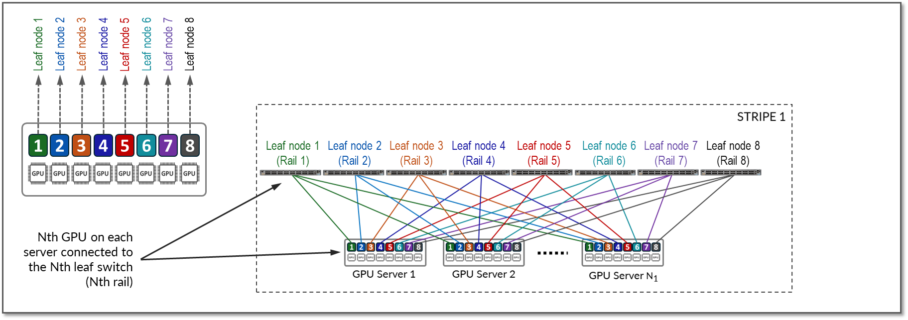
Communication between GPUs in the same server happens internally via high throughput NV-Links (Nvidia links) channels attached to internal NV-Switches, while communication between GPUs in different servers happens across the QFX fabric, which provides 400Gbps GPU-to-GPU bandwidth. Communication across the fabric occurs between GPUs on the same rail, which is the basis of the Rail-optimized architecture: Rails connect GPUs of the same order across one of the leaf nodes; that is, rail N connects GPUs in position N in all the servers across leaf switch N.
Figure 12 represents a topology with one stripe and 8 rails connecting GPUs 1-8 across leaf switches 1-8 respectively.
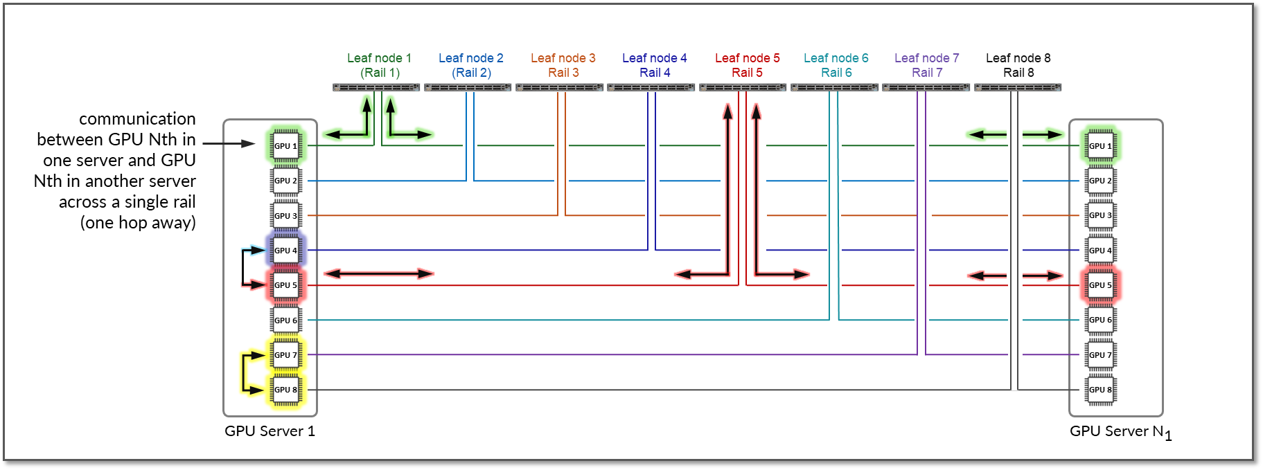
The example shows that communication between GPU 7 and GPU 8 in Server 1 happens internally across Nvidia’s NVlinks/NV-switch (not shown), while communication between GPU 1 in Server 1 and GPU 1 in Server N1 happens across Leaf switch 1 (within the same rail).
Notice that if any communication between GPUs in different stripes and different servers is required (e.g. GPU 4 in server 1 communicating with GPU 5 in Server N1), data is first moved to a GPU interface in the same rail as the destination GPU, thus sending data to the destination GPU without crossing rails.
Following this design, data between GPUs on different servers (but in the same stripe) is always moved on the same rail and across one single switch, which guarantees GPUs are 1 hop away from each other and creates separate independent high-bandwidth channels, which minimize contention and maximize performance.
Notice that this example is presuming Nvidia’s PXN feature is enabled. PXN can be easily enabled/disabled before a training or inference job in initiated.
Figure 12: GPU to GPU Communication Between Two Servers with PXN Enabled
For reference, Figure 13 shows an example with PXN disabled.
Figure 13: GPU to GPU Communication Between Two Servers Without PXN Enabled
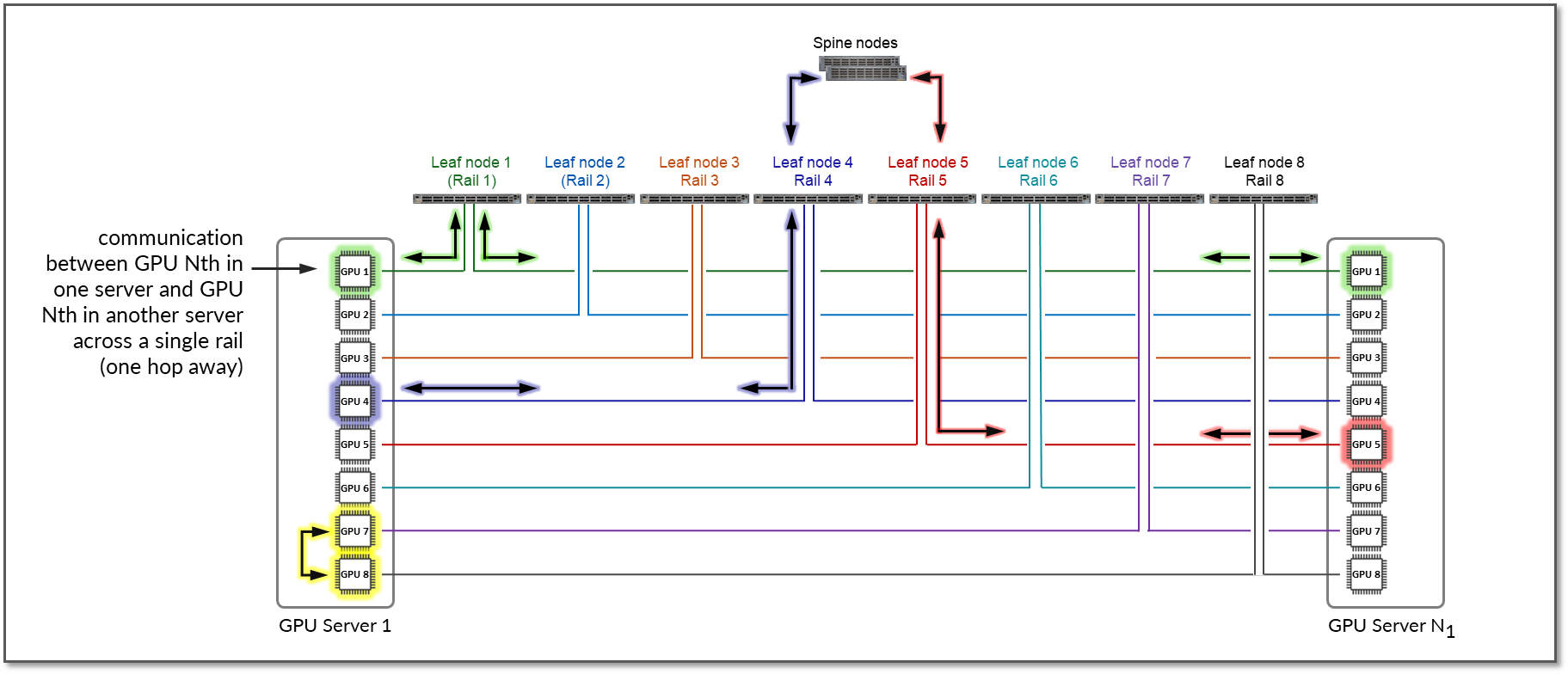
The example shows that communication between GPU 4 in Server 1 and GPU 5 in Server N1 goes across Leaf switch 1, the Spine nodes, and Leaf switch 5 (between two different rails).