Network Connectivity: Reference Examples
For those who want more details, this section provides insight into the setup of each fabric and the expected values for the reference examples.
The section describes the IP connectivity across the common Frontend, and Storage Backend fabrics, and the GPU Backend fabric in Cluster 1, Stripe 1. The GPU Backend fabrics for cluster 1, stripe 2, and cluster 2 follow the same model.
Regardless of whether you are using Apstra with or without Terraform automation with Apstra, the IP addressing Pools, ASN Pools, and interface addresses are largely automatically assigned and configured with little interaction from the administrator unless desired.
Notice that all the addresses shown in this section represent the IP addressing schema used in the Juniper lab to validate the design.
Frontend Network Connectivity
The Frontend fabric is designed as a Layer 3 IP Fabric, where the links between the leaf and spine nodes are configured with /31 IP addresses, as shown in Table 26. The fabric consists of 2 spine nodes and 2 leaf nodes, where 1 leaf node is used to connect to the storage servers (named frontend-weka-leaf 1) and 1 is used to connect to the GPU servers (named frontend-ai-leaf1). Additionally, the Headend Servers that execute the workload manager (Slurm) for AI Training and Inference models reside in this fabric.
There are two 400GE links between each frontend-weka-leaf 1 node and the spine nodes and two 400GE links between each frontend-ai-leaf1 node and the spine nodes as shown in Figure 71.
Figure 71: Frontend Spine to Leaf Nodes Connectivity
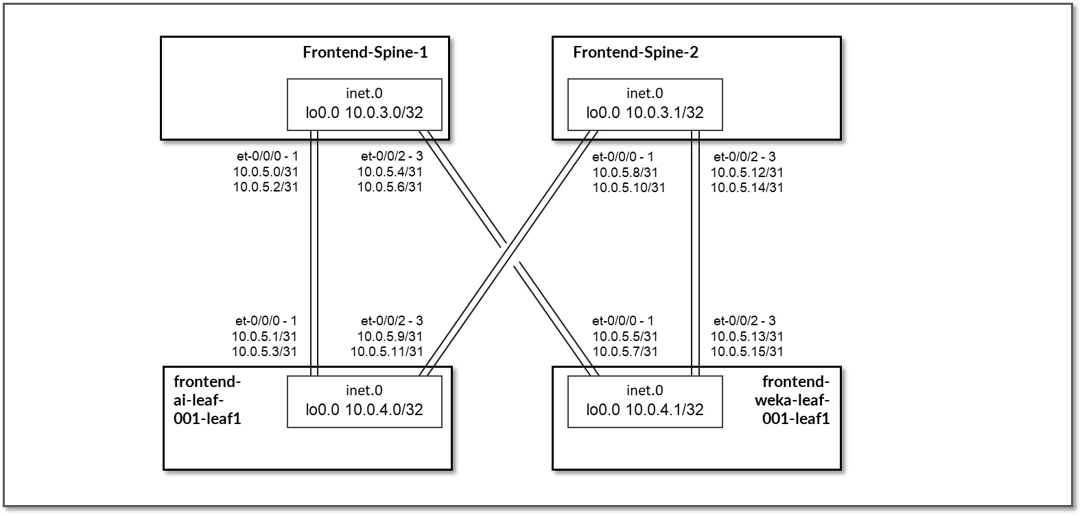
Table 26: Frontend Interface Addresses
| Spine node | Leaf node | Spine IP address | Leaf IP address |
|---|---|---|---|
| frontend-spine1 | frontend-ai-leaf1 |
10.0.5.0/31 10.0.5.2/31 |
10.0.5.1/31 10.0.5.3/31 |
| frontend-spine1 | frontend-weka-leaf1 |
10.0.5.4/31 10.0.5.6/31 |
10.0.5.5/31 10.0.5.7/31 |
| frontend-spine2 | frontend-ai-leaf1 |
10.0.5.8/31 10.0.5.10/31 |
10.0.5.9/31 10.0.5.11/31 |
| frontend-spine2 | frontend-weka-leaf1 |
10.0.5.12/31 10.0.5.14/31 |
10.0.5.13/31 10.0.5.15/31 |
The loopback interfaces also have addresses automatically assigned by Apstra from a predefined pool.
Table 27: Frontend Loopback Addresses
| Device | Loopback interface address |
|---|---|
| frontend-spine1 | 10.0.3.0/32 |
| frontend-spine2 | 10.0.3.1/32 |
| frontend-ai-leaf1 | 10.0.1.0/32 |
| frontend-weka-leaf1 | 10.0.1.1/32 |
The H100 GPU Servers and A100 GPU Servers are all connected to the frontend-ai-leaf1 node.
The links between the GPU servers and the leaf node Leaf 1 are assigned /31 subnets out of 10.0.5.0/24, shown in Figure 72 and Table 28.
Figure 72: Frontend Leaf Nodes to GPU Servers Connectivity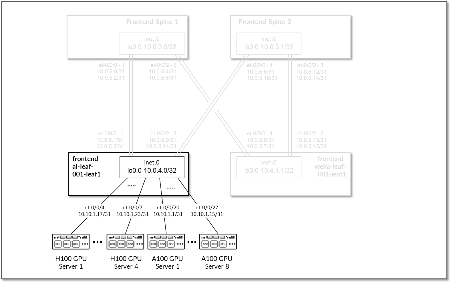
Table 28: Frontend Leaf Nodes to GPU Servers Interfaces Addresses
| GPU Server | Leaf node | GPU Server IP address | Leaf IP address |
|---|---|---|---|
| H100 GPU Server 1 | frontend-ai-leaf1 | 10.10.1.17/31 | 10.100.1.9/31 |
| H100 GPU Server 2 | 10.10.1.19/31 | 10.100.1.11/31 | |
| H100 GPU Server 3 | 10.10.1.21/31 | 10.100.1.1/31 | |
| H100 GPU Server 4 | 10.10.1.23/31 | 10.100.1.3/31 | |
| A100 GPU Server 1 | 10.10.1.1/31 | 10.100.1.5/31 | |
| A100 GPU Server 2 | 10.10.1.3/31 | 10.100.1.7/31 | |
| A100 GPU Server 3 | 10.10.1.5/31 | 10.100.2.9/31 | |
| A100 GPU Server 4 | 10.10.1.7/31 | 10.100.2.11/31 | |
| A100 GPU Server 5 | 10.10.1.9/31 | 10.100.2.1/31 | |
| A100 GPU Server 6 | 10.10.1.11/31 | 10.100.2.3/31 | |
| A100 GPU Server 7 | 10.10.1.13/31 | 10.100.2.5/31 | |
| A100 GPU Server 8 | 10.10.1.15/31 | 10.100.2.7/31 |
The WEKA storage servers are all connected to the frontend-weka-leaf 1 node.
The links to these servers do not have IP addresses assigned on the leaf node. Layer 3 connectivity is provided via an irb interface with an address out of subnet 10.10.2.1/24. The WEKA servers are assigned addresses out of 10.10.2.0/24, as shown Figure 73 and Table 29.
Figure 73: Frontend Leaf Nodes to WEKA Storage Connectivity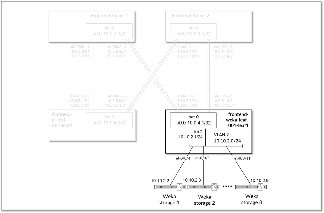
Table 29: Frontend Leaf Nodes to WEKA Storage Interface Addresses
| GPU Server | Leaf node | WEKA Server IP Address | Leaf IP Address |
|---|---|---|---|
| WEKA Storage Server 1 | frontend-weka-leaf1 | 10.10.2.2/24 | 10.10.2.1/24 (irb.2) |
| WEKA Storage Server 2 | 10.10.2.3/24 | ||
| WEKA Storage Server 3 | 10.10.2.4/24 | ||
| WEKA Storage Server 4 | 10.10.2.5/24 | ||
| WEKA Storage Server 5 | 10.10.2.6/24 | ||
| WEKA Storage Server 6 | 10.10.2.7/24 | ||
| WEKA Storage Server 7 | 10.10.2.8/24 | ||
| WEKA Storage Server 8 | 10.10.2.9/24 |
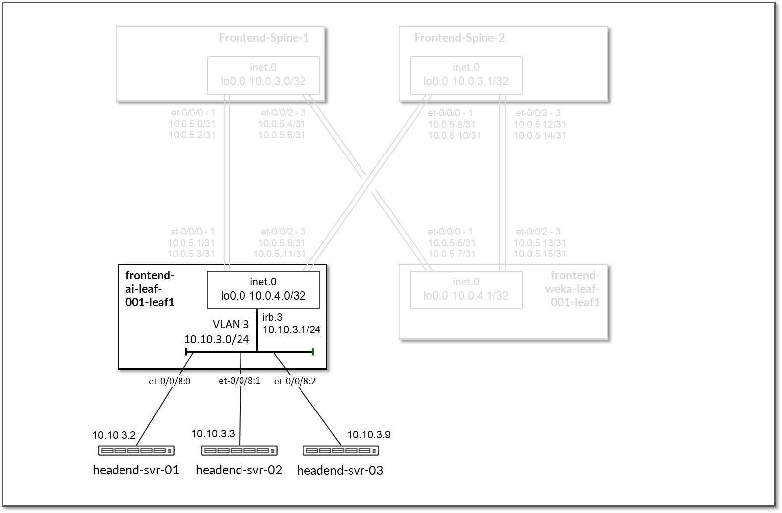
The Headend servers executing the workload manager are all connected to the frontend-ai-leaf1 node.
The links to these servers do not have IP addresses assigned on the leaf node. Layer 3 connectivity is provided via an irb interface with the address 10.10.3.1/24. The headend servers assigned addresses out of 10.10.3.0/24, as shown in Figure 74 and table below.
Figure 74: Frontend Leaf Nodes to Headend Servers Connectivity
EBGP is configured between the IP addresses assigned to the spine-leaf nodes links. There will be 2 EBGP sessions between the frontend-ai-leaf# node and each spine node, and 2 EBGP sessions between each frontend-weka-leaf # node and each of the spine nodes, as shown in Figure 75.
Figure 75: Frontend EBGP
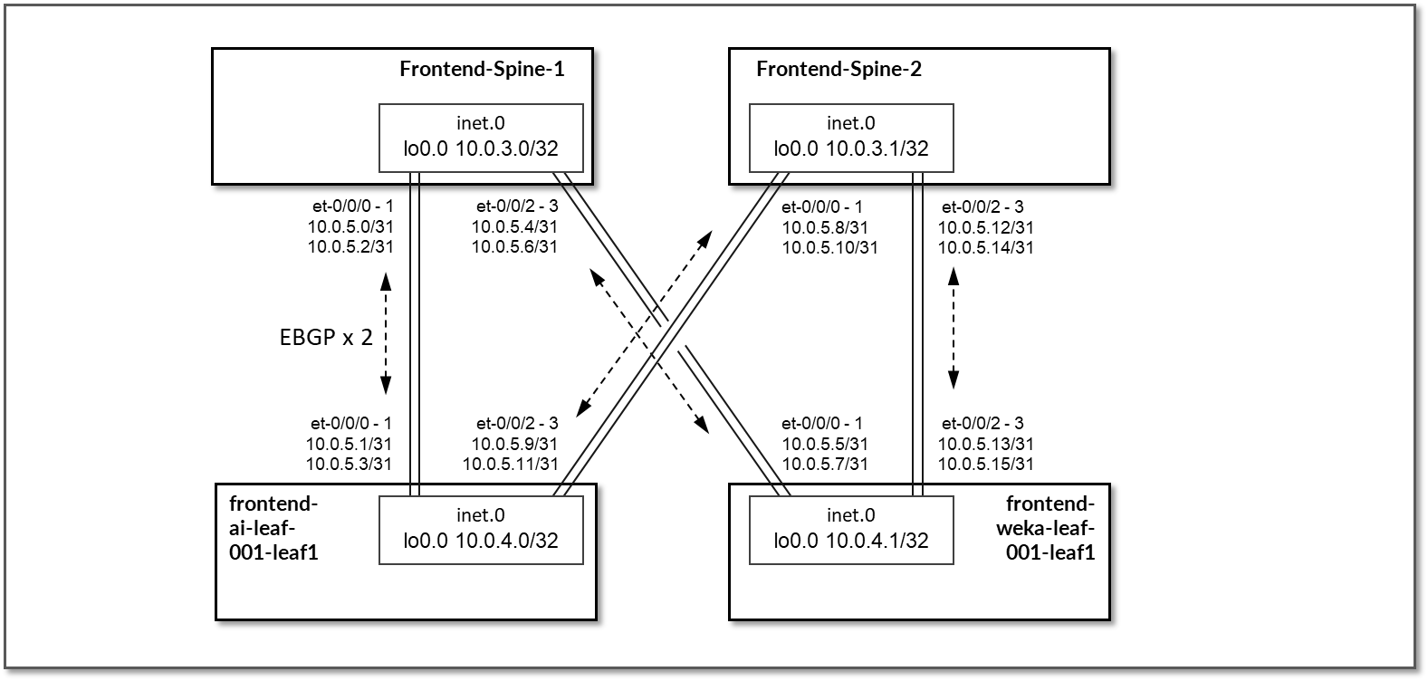
Table 30: Frontend Sessions
| Spine node | Leaf node | Spine | Leaf ASN | Spine IP address | Leaf IP address |
|---|---|---|---|---|---|
| frontend-spine1 | frontend-ai-leaf1 | 4201032300 | 4201032400 |
10.0.5.0/31 10.0.5.2/31 |
10.0.5.1/31 10.0.5.3/31 |
| frontend-spine1 | frontend-weka-leaf 1 | 4201032401 |
10.0.5.4/31 10.0.5.6/31 |
10.0.5.4/31 10.0.5.7/31 |
|
| frontend-spine2 | frontend-ai-leaf1 | 4201032301 | 4201032400 |
10.0.5.8/31 10.0.5.10/31 |
10.0.5.9/31 10.0.5.11/31 |
| frontend-spine2 | frontend-weka-leaf 1 | 4201032401 |
10.0.5.12/31 10.0.5.14/31 |
10.0.5.13/31 10.0.5.15/31 |
On the frontend-ai-leaf1 nodes BGP policies are configured by Apstra to advertise the following routes to the spine nodes:
- frontend-ai-leaf1 node own loopback interface address,
- frontend-ai-leaf1 node to spines interfaces subnets and
- GPU servers to frontend-ai-leaf1 node link subnets.
- WEKA server’s management subnet
Figure 76: Frontend Leaf to GPU Servers BGP
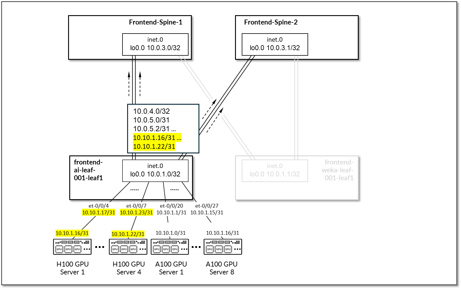
Figure 77: Frontend Leaf to Headend Server BGP
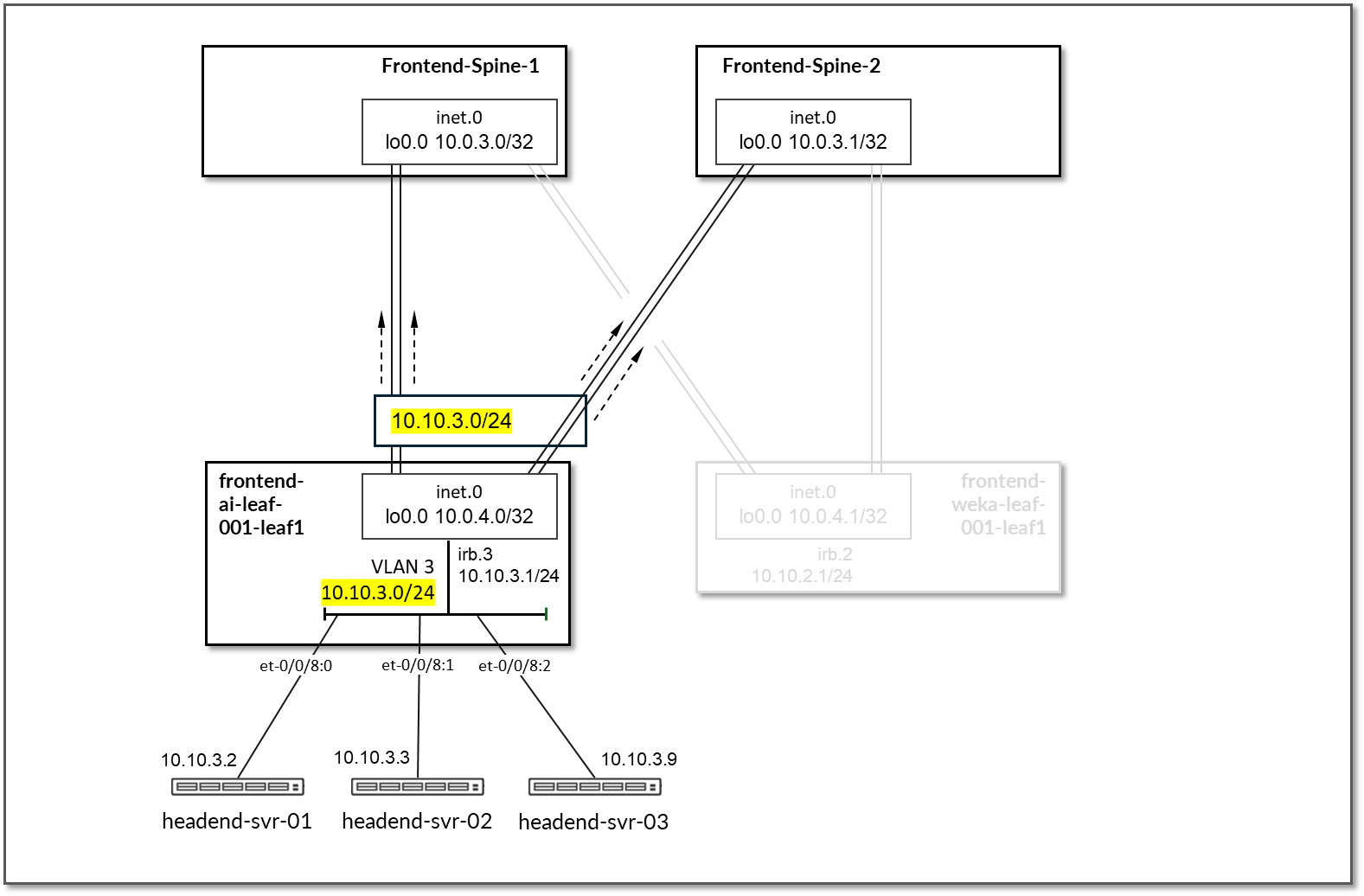
Table 31: Frontend Leaf to GPU/Headend Servers Advertised Routes
| Leaf Node | Peer(s) | Advertised Routes | BGP Communities | |
|---|---|---|---|---|
| frontend-ai-leaf1 | frontend-spine1 & frontend-spine2 |
Loopback: 10.0.4.0/32 Leaf-spines links: 10.0.5.0/31 10.0.5.2/31 10.0.5.8/31 10.0.5.10/31 |
GPU servers <=> frontend spine links: 10.10.1.16/31 10.10.1.18/31 10.10.1.20/31 10.10.1.22/31 10.10.1.0/31 10.10.1.2/31 10.10.1.4/31 10.10.1.6/31 10.10.1.8/31 10.10.1.10/31 10.10.1.12/31 10.10.1.14/31 WEKA Management server’s subnet: 10.10.3.0/24 |
3:20007 21001:26000 |
On the frontend-weka-leaf 1 node BGP policies are configured by Apstra to advertise the following routes to the spine nodes:
- frontend-weka-leaf 1 node own loopback interface address,
- frontend-weka-leaf 1 node to spines interfaces subnets and
- WEKA storage server’s subnet
Figure 78: Frontend Leaf to WEKA Storage BGP
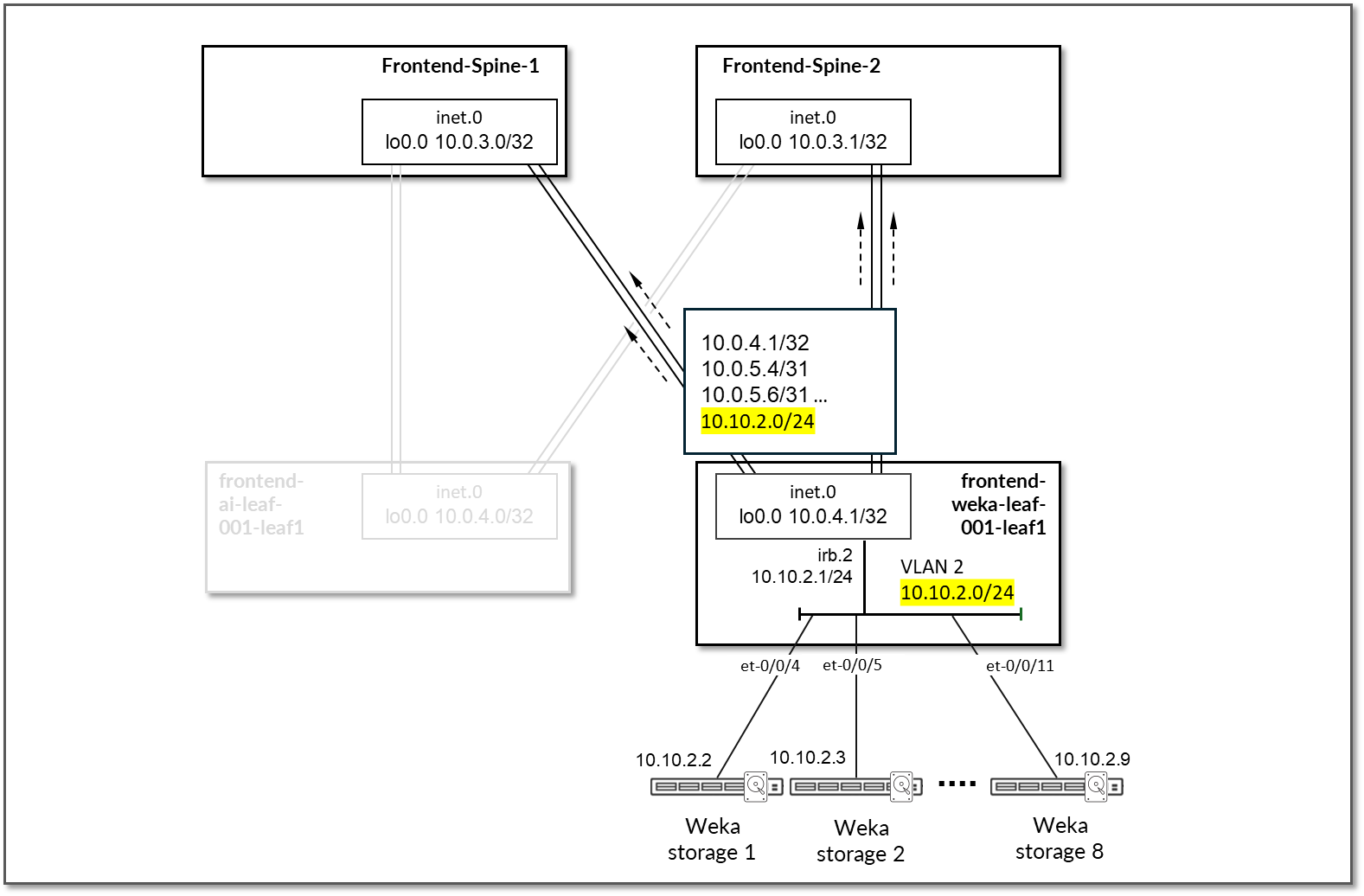
Table 32: Frontend Leaf to Weka Storage Advertised Routes
| Leaf Node | Peer(s) | Advertised Routes | BGP Communities | |
|---|---|---|---|---|
| frontend-weka-leaf 1 |
frontend-spine1 & frontend-spine2 |
Loopback: 10.0.4.1/32 Leaf-spines links: 10.0.5.4/31 10.0.5.6/31 10.0.5.12/31 10.0.5.14/31 |
GPU servers <=> frontend spine links: 10.10.2.0/24 |
4:20007 21001:26000 |
On the Spine nodes, BGP policies are configured by Apstra to advertise the following routes to the frontend-ai-leaf node:
- frontend-spine node own loopback interface address
- frontend-weka-leaf 1 loopback interface address
- frontend-spine to frontend-weka-leaf 1 nodes interfaces subnets
- WEKA storage server’s subnet (learned from frontend-weka-leaf 1)
Figure 79: Frontend Spine to Frontend Leaf for GPU/Headed
Servers BGP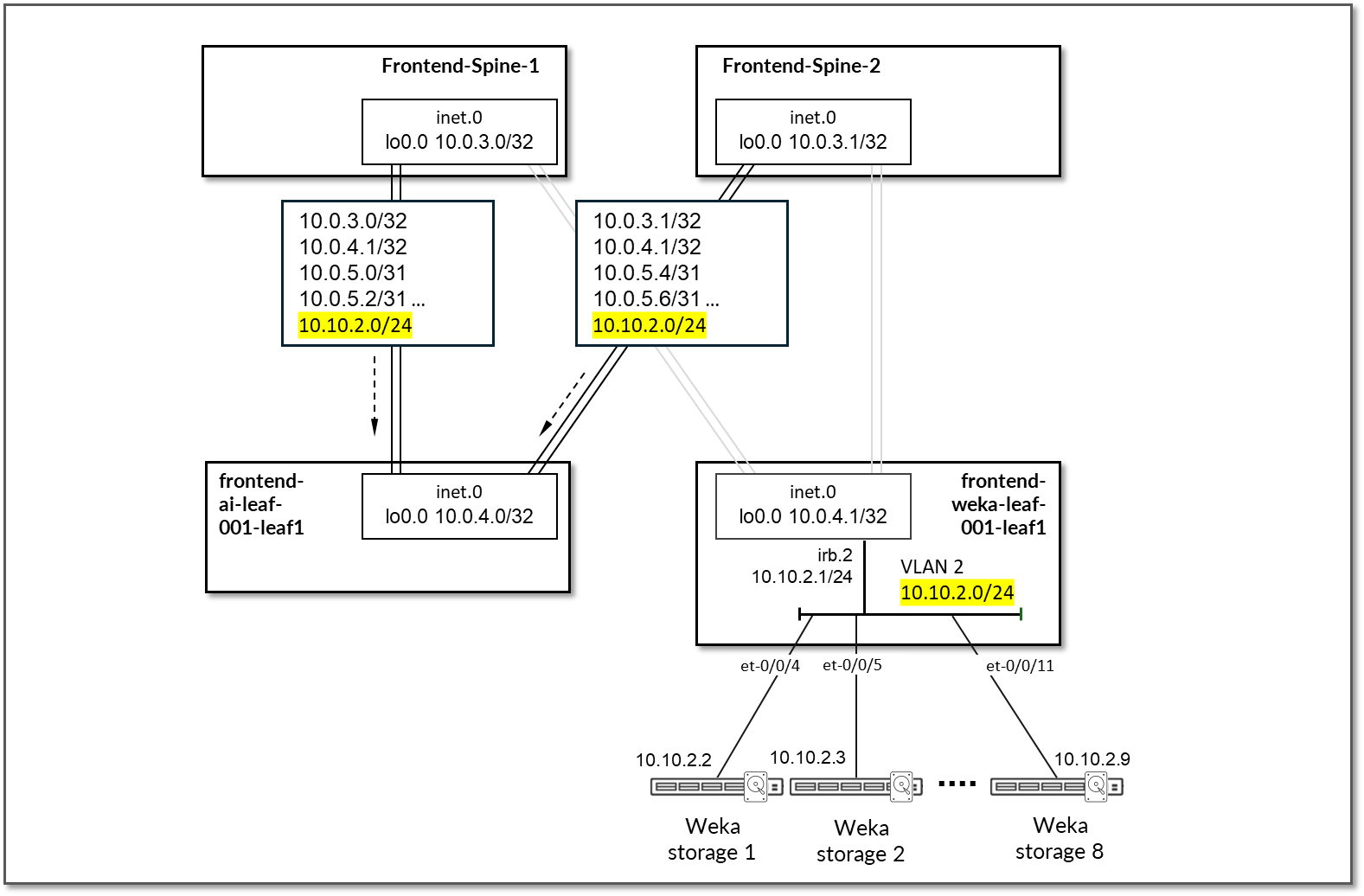
Table 33: Frontend Spine to Frontend Leaf for GPU/Headed Servers Advertised Routes
| Leaf Node | Peer(s) | Advertised Routes | BGP Communities | |
|---|---|---|---|---|
| frontend-spine1 | frontend-ai-leaf |
Loopback: 10.0.3.0/32 10.0.4.0/32 Leaf-spines links: 10.0.5.0/31 10.0.5.2/31 10.0.5.4/31 10.0.5.6/31 10.0.5.12/31 10.0.5.14/31 |
WEKA Servers subnet: 10.10.2.0/24 |
0:15 1:20007 21001:26000 Except for 10.0.4.0/32 (0:15 3:20007 21001:26000) |
| frontend-spine2 | frontend-ai-leaf |
Loopbacks: 10.0.3.1/32 10.0.4.0/32 Leaf-spines links: 10.0.5.4/31 10.0.5.6/31 10.0.5.8/31 10.0.5.10/31 10.0.5.12/31 10.0.5.14/31 |
WEKA Servers subnet: 10.10.2.0/24 |
0:15 2:20007 21001:26000 Except for 10.0.4.0/32 (0:15 3:20007 21001:26000) |
On the Spine nodes, BGP policies are configured by Apstra to advertise the following routes to the frontend-weka-leaf 1 leaf node:
- spine node own loopback interface address
- frontend-ai-leaf1 loopback interface address
- spine to frontend-ai-leaf1 nodes interfaces subnets
- GPU servers to frontend-ai-leaf1 node link subnets
Figure 80: Frontend Spine to Frontend Leaf for WEKA Storage Headend Server BGP
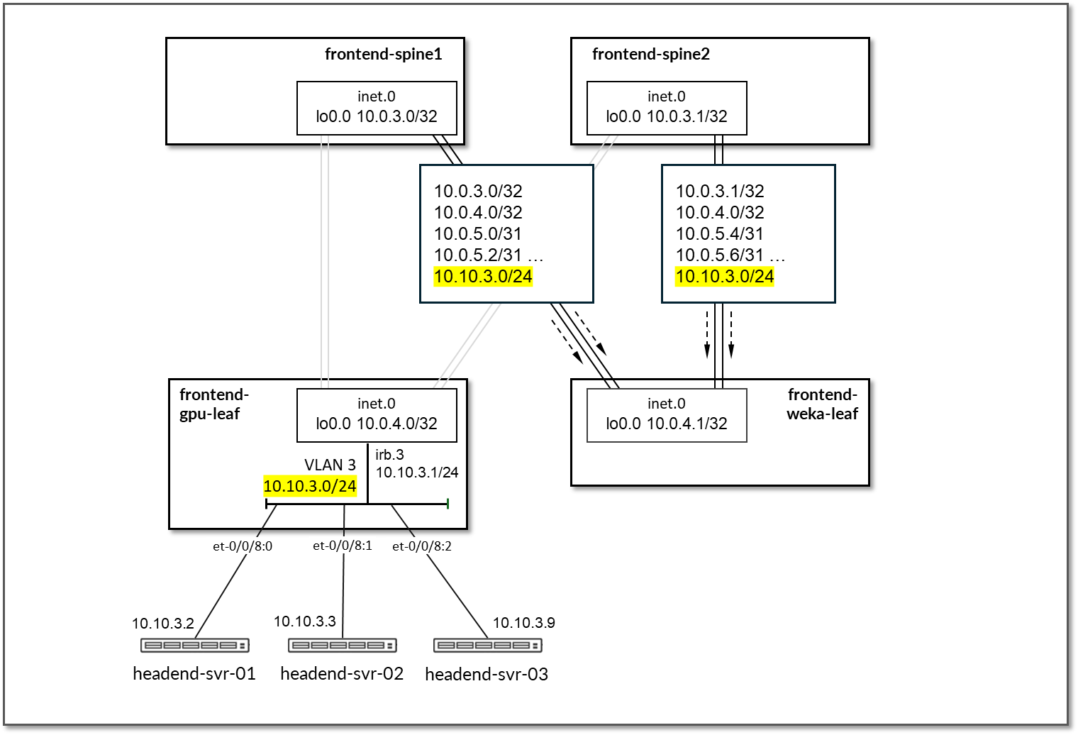
Figure 81: Frontend Spine to Frontend Leaf for WEKA Storage GPU Server BGP
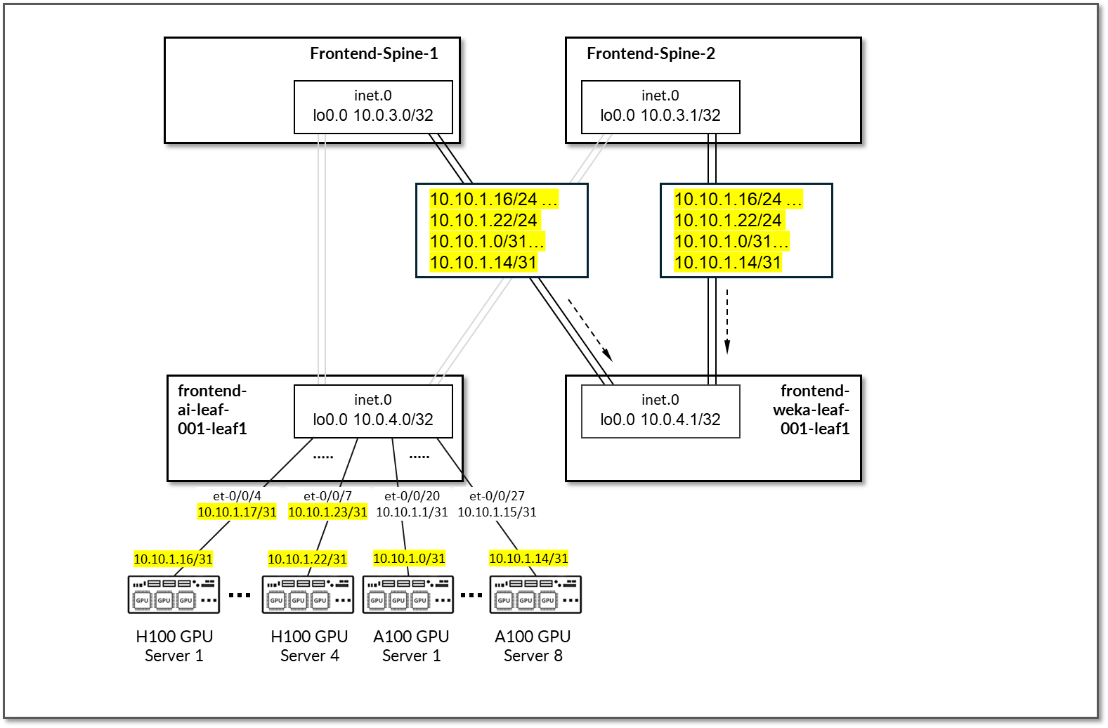
Table 34 Frontend Spine to Frontend Leaf for WEKA Storage Advertised Routes
| Leaf Node | Peer(s) | Advertised Routes | BGP Communities | |
|---|---|---|---|---|
| frontend-spine1 | frontend-ai-leaf |
Loopback: 10.0.3.0/32 10.0.4.1/32 Leaf-spines links: 10.0.5.0/31 10.0.5.2/31 10.0.5.4/31 10.0.5.6/31 10.0.5.8/31 10.0.5.10/31 |
GPU server <=> frontend spine links: 10.10.1.16/31 10.10.1.18/31 10.10.1.20/31 10.10.1.22/31 10.10.1.0/31 10.10.1.2/31 10.10.1.4/31 10.10.1.6/31 10.10.1.8/31 10.10.1.10/31 10.10.1.12/31 10.10.1.14/31 WEKA Server’s Management subnet: 10.10.3.0/24 |
0:15 1:20007 21001:26000 Except for 10.0.4.1/32 (0:15 4:20007 21001:26000) |
| frontend-spine2 | frontend-ai-leaf |
Loopbacks: 10.0.3.1/32 10.0.4.1/32 Leaf-spines links: 10.0.5.0/31 10.0.5.2/31 10.0.5.8/31 10.0.5.10/31 10.0.5.12/31 10.0.5.14/31 |
GPU servers <=> frontend spine links: 10.10.1.16/31 10.10.1.18/31 10.10.1.20/31 10.10.1.22/31 10.10.1.0/31 10.10.1.2/31 10.10.1.4/31 10.10.1.6/31 10.10.1.8/31 10.10.1.10/31 10.10.1.12/31 10.10.1.14/31 WEKA Management server’s subnet: 10.10.3.0/24 |
0:15 2:20007 21001:26000 Except for 10.0.4.1/32 (0:15 4:20007 21001:26000) |
By advertising the subnet assigned to the links between the leaf nodes and the GPU/storage servers, communication between GPUs and the WEKA storage and WEKA management servers is possible across the fabric.
Figure 82: GPU Server to WEKA storage and WEKA Management
Servers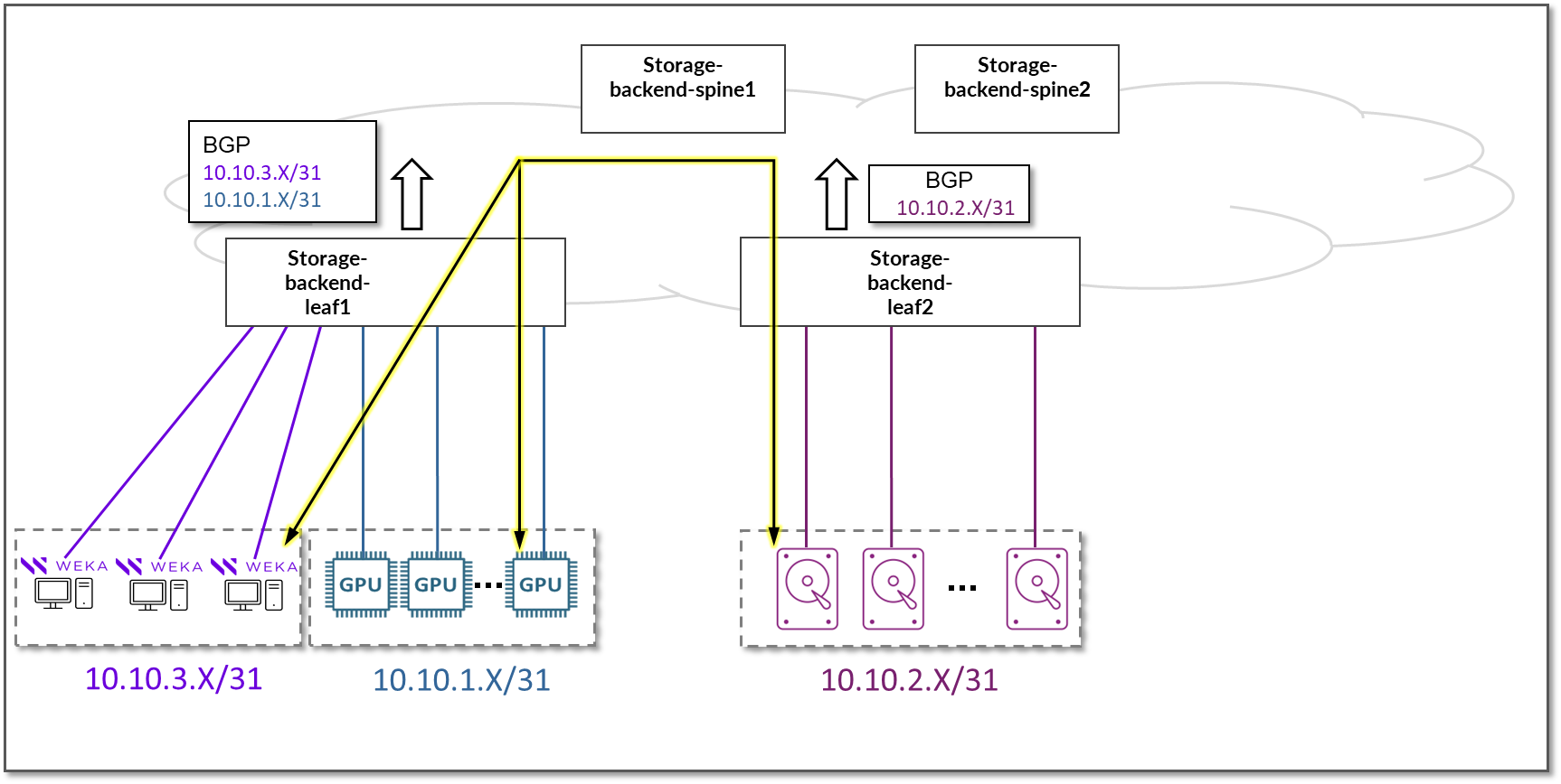
GPU Backend Network Connectivity
The GPU Backend fabric is designed as a Layer 3 IP Fabric, where the links between the leaf and spine nodes are configured with /31 IP addresses and are running EBGP. The fabric consists of 2 spine nodes, and 8 spine nodes (per stripe).
There is a single 400GE link between each leaf node and the spine nodes.
Figure 83: GPU Backend Spine to GPU Backend Leaf Nodes
Connectivity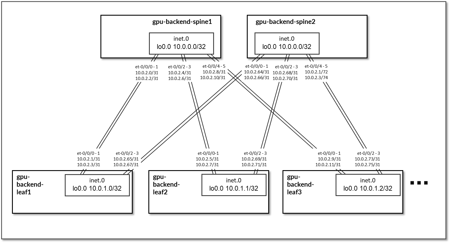
Table 35: GPU Backend Interface Addresses
| Stripe # | Spine node | Leaf node | Spine IP address | Leaf IP address |
|---|---|---|---|---|
| 1 | gpu-backend-spine 1 | gpu-backend-leaf1 |
10.0.2.0/31 10.0.2.2/31 |
10.0.2.1/31 10.0.2.3/31 |
| 1 | gpu-backend-spine 1 | gpu-backend-leaf2 |
10.0.2.4/31 10.0.2.6/31 |
10.0.2.5/31 10.0.2.7/31 |
| 1 | gpu-backend-spine 1 | gpu-backend-leaf3 |
10.0.2.8/31 10.0.2.10/31 |
10.0.2.9/31 10.0.2.11/31 |
|
. . . |
||||
| 1 | gpu-backend-spine 2 | gpu-backend-leaf1 |
10.0.2.64/31 10.0.2.66/31 |
10.0.2.65/31 10.0.2.67/31 |
| 1 | gpu-backend-spine 2 | gpu-backend-leaf2 |
10.0.2.68/31 10.0.2.70/31 |
10.0.2.69/31 10.0.2.71/31 |
| 1 | gpu-backend-spine 2 | gpu-backend-leaf3 |
10.0.2.72/31 10.0.2.74/31 |
10.0.2.73/31 10.0.2.75/31 |
The loopback interfaces also have addresses automatically assigned by Apstra from a predefined pool.
Table 36: GPU Backend Loopback Addresses
| Stripe # | Device | Loopback Interface Address |
|---|---|---|
| 1 | gpu-backend-spine1 | 10.0.0.0/32 |
| 1 | gpu-backend-spine2 | 10.0.0.1/32 |
| 1 | gpu-backend-leaf1 | 10.0.1.0/32 |
| 1 | gpu-backend-leaf2 | 10.0.1.1/32 |
| 1 | gpu-backend-leaf3 | 10.0.1.2/32 |
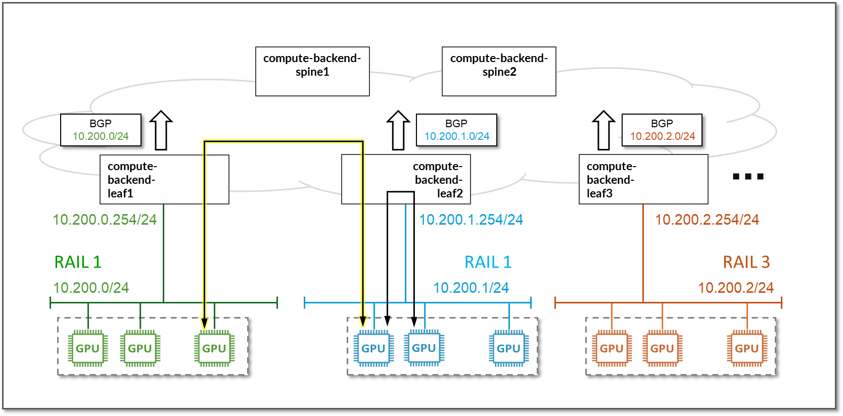
Each leaf node is assigned a /24 subnet out of 10.200/16 and a unique VLAN ID to provide connectivity to the GPU servers. Layer 3 connectivity is provided via an irb interface with an address out of the specific IP subnet, as shown in the table below.
Because each leaf node represents a rail, where all the GPUs with a given number connect, each rail in the cluster is mapped to a different /24 IP subnet.
Figure 84: GPU Backend Servers to Leaf Nodes Connectivity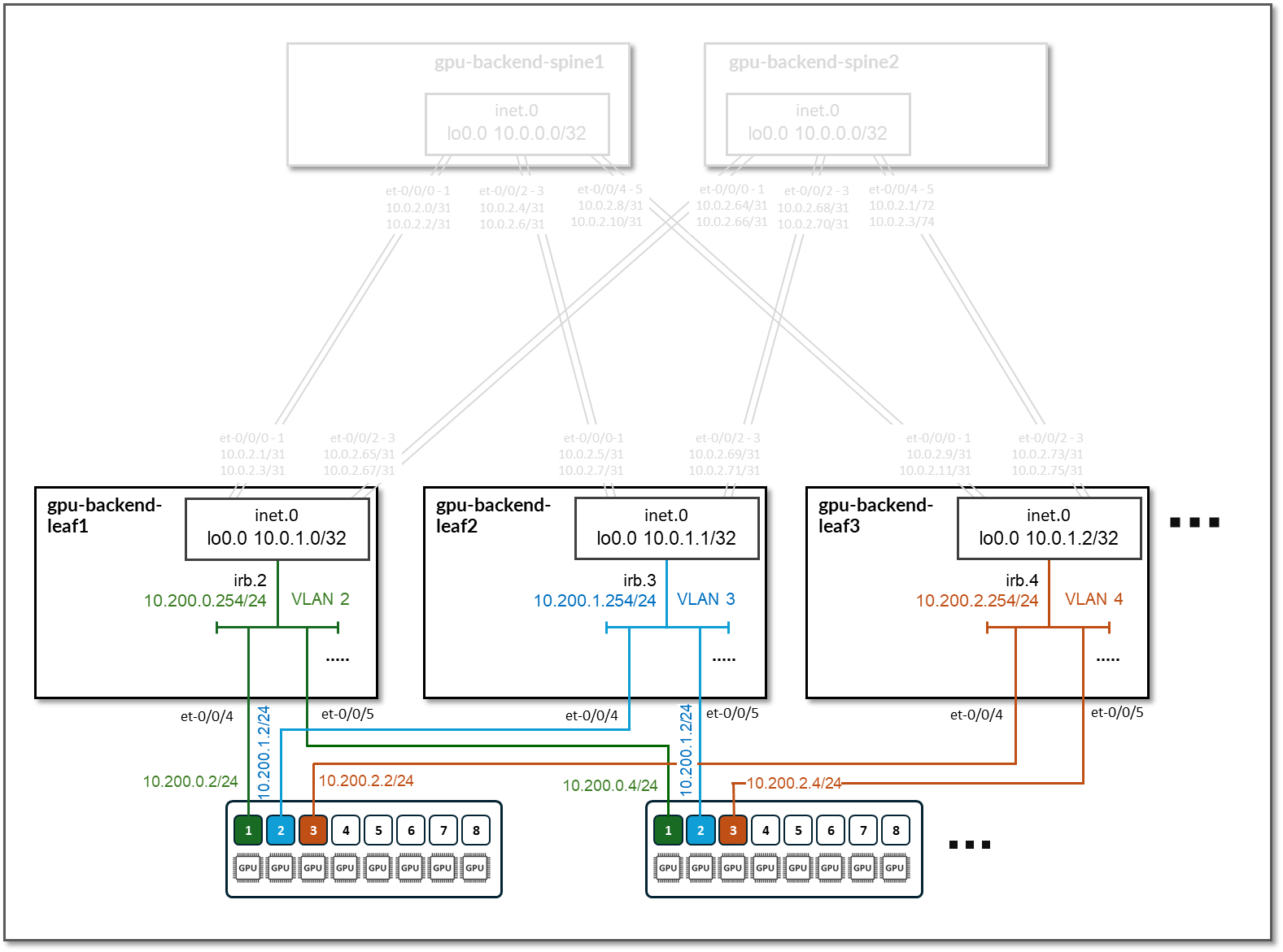
Table 37: GPU Backend Servers to Leaf Nodes Connectivity
| Stripe # | Device | Rail # | VLAN # | Subnet | IRB on leaf | Connected device(s) |
|---|---|---|---|---|---|---|
| 1 | gpu-backend-leaf 1 | 1 | 2 | 10.200.0.0/24 | 10.200.0.254 | GPU 1 from all 8 GPU servers |
| 1 | gpu-backend-leaf 2 | 2 | 3 | 10.200.1.0/24 | 10.200.1.254 | GPU 2 from all 8 GPU servers |
| 1 | gpu-backend-leaf 3 | 3 | 4 | 10.200.2.0/24 | 10.200.2.254 | GPU 3 from all 8 GPU servers |
|
. . . |
||||||
EBGP is configured between the IP addresses assigned to the spine-leaf nodes links, as shown in Figure 81. There will be 2 EBGP sessions between each gpu-backend-leaf # node and each gpu-backend-spine #.
Figure 85: GPU Backend BGP Sessions
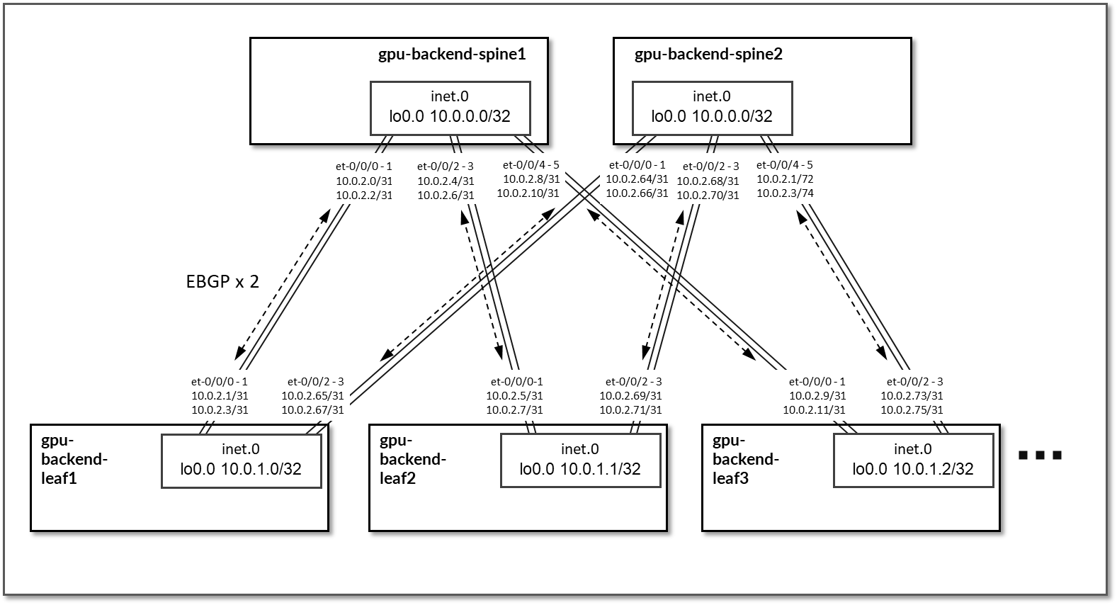
Table 38: GPU Backend Sessions
| Stripe # | Spine Node | Leaf Node | Spine ASN | Leaf ASN | Spine IP Address | Leaf IP Address |
|---|---|---|---|---|---|---|
| 1 | gpu-backend-spine1 | gpu-backend-leaf1 | 4201032100 | 4201032200 |
10.0.2.0/31 10.0.2.2/31 |
10.0.2.1/31 10.0.2.3/31 |
| 1 | gpu-backend-spine1 | gpu-backend-leaf2 | 4201032201 |
10.0.2.4/31 10.0.2.6/31 |
10.0.2.5/31 10.0.2.7/31 |
|
| 1 | gpu-backend-spine1 | gpu-backend-leaf3 | 4201032202 |
10.0.2.8/31 10.0.2.10/31 |
10.0.2.9/31 10.0.2.11/31 |
|
|
. . . |
||||||
| 1 | gpu-backend-spine2 | gpu-backend-leaf1 | 4201032101 | 4201032200 |
10.0.2.64/31 10.0.2.66/31 |
10.0.2.65/31 10.0.2.67/31 |
| 1 | gpu-backend-spine2 | gpu-backend-leaf2 | 4201032201 |
10.0.2.68/31 10.0.2.70/31 |
10.0.2.69/31 10.0.2.71/31 |
|
| 1 | gpu-backend-spine2 | gpu-backend-leaf3 | 4201032202 |
10.0.2.72/31 10.0.2.74/31 |
10.0.2.73/31 10.0.2.75/31 |
|
| . . . |
On the Leaf nodes, BGP policies are configured by Apstra to advertise the following routes to the spine nodes:
- Leaf node own loopback interface address
- leaf to spine interfaces subnets and
- irb interface subnet
Figure 86: GPU Backend Leaf Node BGP
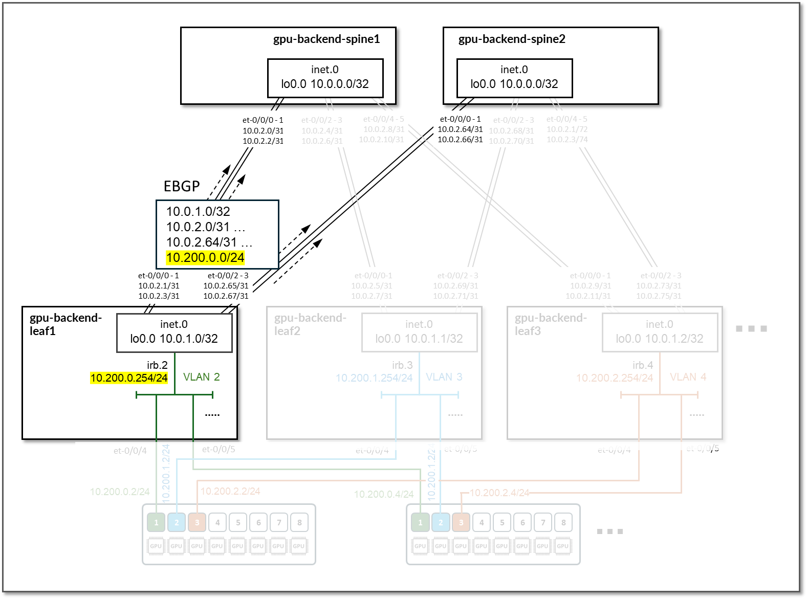
Table 39: GPU Backend Leaf Node Advertised Routes
| Stripe # | Device | Advertised routes | BGP community |
|---|---|---|---|
| 1 | gpu-backend-leaf 1 |
10.0.1.0/32 10.0.2.0/31 10.0.2.64/31 10.200.0.0/24 |
3:20007 21001:26000 |
| 1 | gpu-backend-leaf 2 |
10.0.1.1/32 10.0.2.4/31 10.0.2.68/31 10.200.1.0/24 |
4:20007 21001:26000 |
| 1 | gpu-backend-leaf 3 |
10.0.1.2/32 10.0.2.8/31 10.0.2.72/31 10.200.2.0/24 |
5:20007 21001:26000 |
On the Spine nodes, BGP policies are configured by Apstra to advertise the following routes to the leaf nodes:
- spine node own loopback interface address
- leaf nodes’ loopback interface address
- spine to leaf interfaces subnets
- irb interface subnet, as shown below:
Figure 87: GPU Backend Spine Node BGP
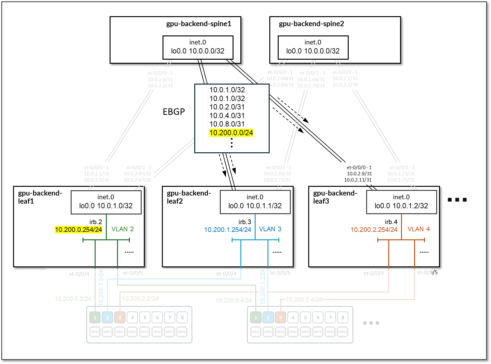
Table 40: GPU Backend Spine Node Advertised Routes
| Stripe # | Spine Node | Advertised Routes | BGP Community |
|---|---|---|---|
| 1 | gpu-backend-spine 1 |
10.0.0.0/32 10.0.2.0/31 10.0.2.4/31 … 10.200.1.0/24 … |
0:15 X:20007 21001:26000 |
| 1 | gpu-backend-spine 2 |
10.0.0.1/32 10.0.2.64/31 10.0.2.68/31 … 10.200.1.0/24 … |
0:15 X:20007 21001:26000 |
By advertising the irb interfaces subnet, communication between GPUs in different rails is possible across the fabric.
Figure 88: Communication Across Rails
Storage Backend Network Connectivity
The Storage Backend fabric is designed as a Layer 3 IP Fabric, where the links between the leaf and spine nodes are configured with /31 IP addresses as shown in the table below. The fabric consists of 2 spine nodes and 4 leaf nodes, where 2 leaf nodes are used to connect the storage servers (named storage-backend-weka-leaf #) and 2 are used to connect to the GPU servers (named storage-backend-gpu-leaf #).
There are three 400GE links between each storage-backend-weka-leaf # node and the spine nodes and two 400GE links between each storage-backend-gpu-leaf # node and the spine nodes as shown in Figure 89.
Figure 89: Storage Backend Spine to Storage Backend GPU Leaf Nodes Connectivity
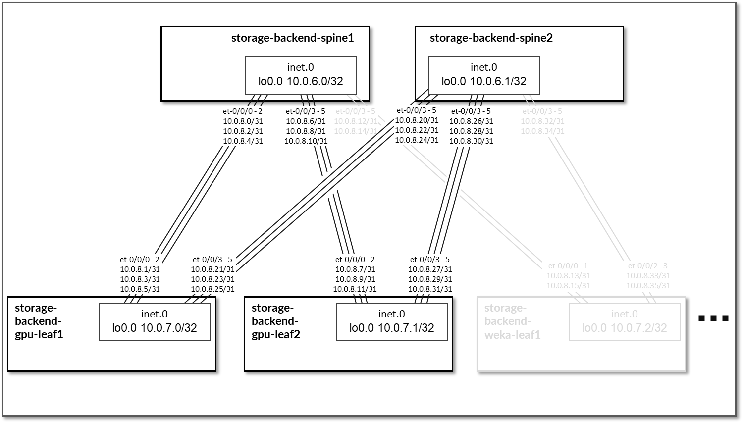
Figure 90: Storage Backend Spine to Storage Backend WEKA Storage Leaf Nodes Connectivity
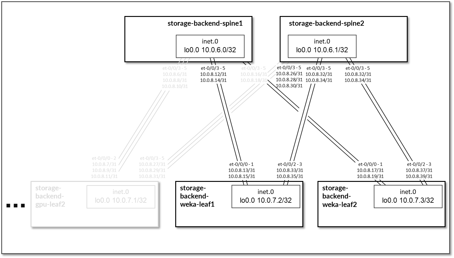
Table 41: Storage Backend Interface Addresses
| Spine node | Leaf node | Spine IP Address | Leaf IP Address |
|---|---|---|---|
| storage-backend-spine 1 | storage-backend-gpu-leaf 1 |
10.0.8.0/31 10.0.8.2/31 10.0.8.4/31 |
10.0.8.1/31 10.0.8.3/31 10.0.8.5/31 |
| storage-backend-spine1 | storage-backend-gpu-leaf2 |
10.0.8.6/31 10.0.8.8/31 10.0.8.10/31 |
10.0.8.7/31 10.0.8.9/31 10.0.8.11/31 |
| storage-backend-spine1 | storage-backend-weka-leaf1 |
10.0.8.12/31 10.0.8.14/31 |
10.0.8.13/31 10.0.8.15/31 |
| storage-backend-spine1 | storage-backend-weka-leaf2 |
10.0.8.16/31 10.0.8.18/31 |
10.0.8.17/31 10.0.8.19/31 |
| storage-backend-spine2 | storage-backend-gpu-leaf1 |
10.0.8.20/31 10.0.8.22/31 10.0.8.24/31 |
10.0.8.21/31 10.0.8.23/31 10.0.8.25/31 |
| storage-backend-spine2 | storage-backend-gpu-leaf2 |
10.0.8.26/31 10.0.8.28/31 10.0.8.30/31 |
10.0.8.27/31 10.0.8.29/31 10.0.8.31/31 |
| storage-backend-spine2 | storage-backend-weka-leaf1 |
10.0.8.32/31 10.0.8.34/31 |
10.0.8.33/31 10.0.8.35/31 |
| storage-backend-spine2 | storage-backend-weka-leaf2 |
10.0.8.36/31 10.0.8.38/31 |
10.0.8.37/31 10.0.8.39/31 |
The loopback interfaces also have addresses automatically assigned by Apstra from a predefined pool.
Table 42: Storage Backend Loopback Interfaces
| Device | Loopback Interface Address |
|---|---|
| storage-backend-spine1 | 10.0.6.0/32 |
| storage-backend-spine2 | 10.0.6.1/32 |
| storage-backend-gpu-leaf1 | 10.0.7.0/32 |
| storage-backend-gpu-leaf2 | 10.0.7.1/32 |
| storage-backend-weka-leaf1 | 10.0.7.2/32 |
| storage-backend-weka-leaf2 | 10.0.7.3/32 |
The H100 GPU Servers and A100 GPU Servers are connected to the storage backend leaf switches as summarized in the following table.
Table 43: Storage GPU Backend Servers to Leaf Nodes Connectivity
| GPU servers | Leaf Node |
|---|---|
| H100-1 | storage-backend-gpu-leaf1 |
| H100-2 | |
| A100-1 | |
| A100-2 | |
| A100-3 | |
| A100-4 | |
| H100-3 | storage-backend-gpu-leaf2 |
| H100-4 | |
| A100-5 | |
| A100-6 | |
| A100-7 | |
| A100-8 |
The links between the GPU servers and storage-backend-gpu-leaf 1 are assigned /31 subnets out of 10.100.1/24, while the links between the GPU servers and storage-backend-gpu-leaf 2 are assigned /31 subnets out of 10.100.2/24, as shown in Figure 91.
Figure 91: GPU Servers to Storage Backend GPU Leaf nodes Connectivity
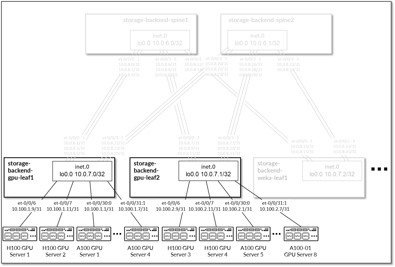
Table 44: GPU Servers to Storage GPU Backend Interface Addresses
| GPU Server | Leaf Node | GPU Server IP Address | Leaf IP Address |
|---|---|---|---|
| H100 GPU Server 1 | storage-backend-gpu-leaf 1 | 10.100.1.8/31 | 10.100.1.9/31 |
| H100 GPU Server 2 | storage-backend-gpu-leaf 1 | 10.100.1.10/31 | 10.100.1.11/31 |
| A100 GPU Server 1 | storage-backend-gpu-leaf 1 | 10.100.1.0/31 | 10.100.1.1/31 |
| A100 GPU Server 2 | storage-backend-gpu-leaf 1 | 10.100.1.2/31 | 10.100.1.3/31 |
| A100 GPU Server 3 | storage-backend-gpu-leaf 1 | 10.100.1.4/31 | 10.100.1.5/31 |
| A100 GPU Server 4 | storage-backend-gpu-leaf 1 | 10.100.1.6/31 | 10.100.1.7/31 |
| H100 GPU Server 3 | storage-backend-gpu-leaf 2 | 10.100.2.8/31 | 10.100.2.9/31 |
| H100 GPU Server 4 | storage-backend-gpu-leaf 2 | 10.100.2.10/31 | 10.100.2.11/31 |
| A100 GPU Server 5 | storage-backend-gpu-leaf 2 | 10.100.2.0/31 | 10.100.2.1/31 |
| A100 GPU Server 6 | storage-backend-gpu-leaf 2 | 10.100.2.2/31 | 10.100.2.3/31 |
| A100 GPU Server 7 | storage-backend-gpu-leaf 2 | 10.100.2.4/31 | 10.100.2.5/31 |
| A100 GPU Server 8 | storage-backend-gpu-leaf 2 | 10.100.2.6/31 | 10.100.2.7/31 |
Like the GPU servers, the WEKA storage servers are connected to the two storage-backend-weka-leaf # nodes as shown Figure 92.
Figure 92: WEKA Storage servers to Leaf Nodes Connectivity
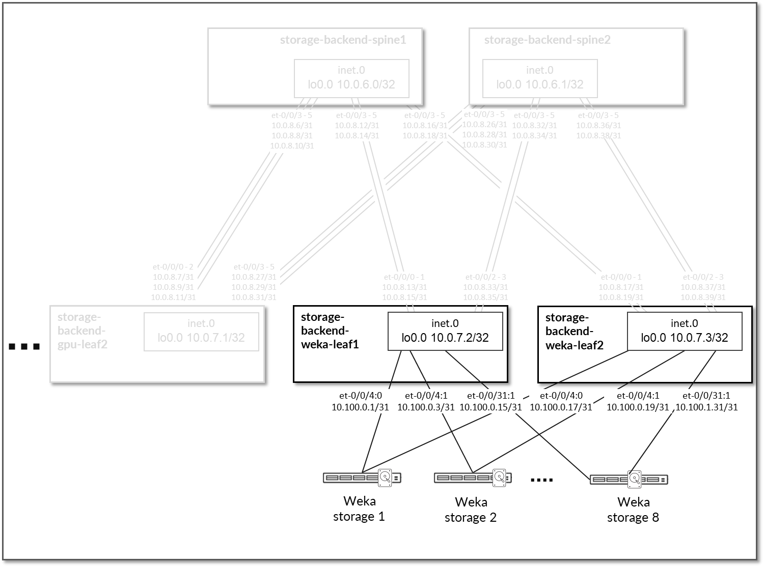
Each GPU server to leaf node connection is assigned a /31 subnet out of 10.100.0.0/24, as shown in the following table.
Table 45: WEKA Storage Servers to Leaf Nodes Interface Addresses
| WEKA Server | Leaf Node | WEKA Server IP Address | Leaf IP Address |
|---|---|---|---|
| WEKA storage Server 1 | storage-backend-weka-leaf 1 | 10.100.0.0/31 | 10.100.0.1/31 |
| WEKA storage Server 2 | storage-backend-weka-leaf 1 | 10.100.0.2/31 | 10.100.0.3/31 |
| WEKA storage Server 3 | storage-backend-weka-leaf 1 | 10.100.0.4/31 | 10.100.0.5/31 |
| WEKA storage Server 4 | storage-backend-weka-leaf 1 | 10.100.0.5/31 | 10.100.0.7/31 |
| WEKA storage Server 5 | storage-backend-weka-leaf 1 | 10.100.0.8/31 | 10.100.0.9/31 |
| WEKA storage Server 6 | storage-backend-weka-leaf 1 | 10.100.0.10/31 | 10.100.0.11/31 |
| WEKA storage Server 7 | storage-backend-weka-leaf 1 | 10.100.0.12/31 | 10.100.0.13/31 |
| WEKA storage Server 8 | storage-backend-weka-leaf 1 | 10.100.0.14/31 | 10.100.0.15/31 |
| WEKA storage Server 1 | storage-backend-weka-leaf 1 | 10.100.0.16/31 | 10.100.0.17/31 |
| WEKA storage Server 2 | storage-backend-weka-leaf 1 | 10.100.0.18/31 | 10.100.0.19/31 |
| WEKA storage Server 3 | storage-backend-weka-leaf 1 | 10.100.0.20/31 | 10.100.0.21/31 |
| WEKA storage Server 4 | storage-backend-weka-leaf 1 | 10.100.0.22/31 | 10.100.0.23/31 |
| WEKA storage Server 5 | storage-backend-weka-leaf 1 | 10.100.0.24/31 | 10.100.0.25/31 |
| WEKA storage Server 6 | storage-backend-weka-leaf 1 | 10.100.0.26/31 | 10.100.0.27/31 |
| WEKA storage Server 7 | storage-backend-weka-leaf 1 | 10.100.0.28/31 | 10.100.0.29/31 |
| WEKA storage Server 8 | storage-backend-weka-leaf 1 | 10.100.0.30/31 | 10.100.0.31/31 |
Notice that the leaf nodes in this case are using physical interfaces to connect to the storage servers. Thus, no irb interface or vlan id are used for this connectivity.
EBGP is configured between the IP addresses assigned to the links between the spine and the leaf nodes as shown in Figure 93.
There will be 3 EBGP sessions between each storage-backend-weka-leaf # node and the spine nodes. Similarly, there will be 2 EBGP sessions between each storage-backend-gpu-leaf # node.
Figure 93: Storage Backend Spine to Storage Backend Leave for GPU Servers EBGP
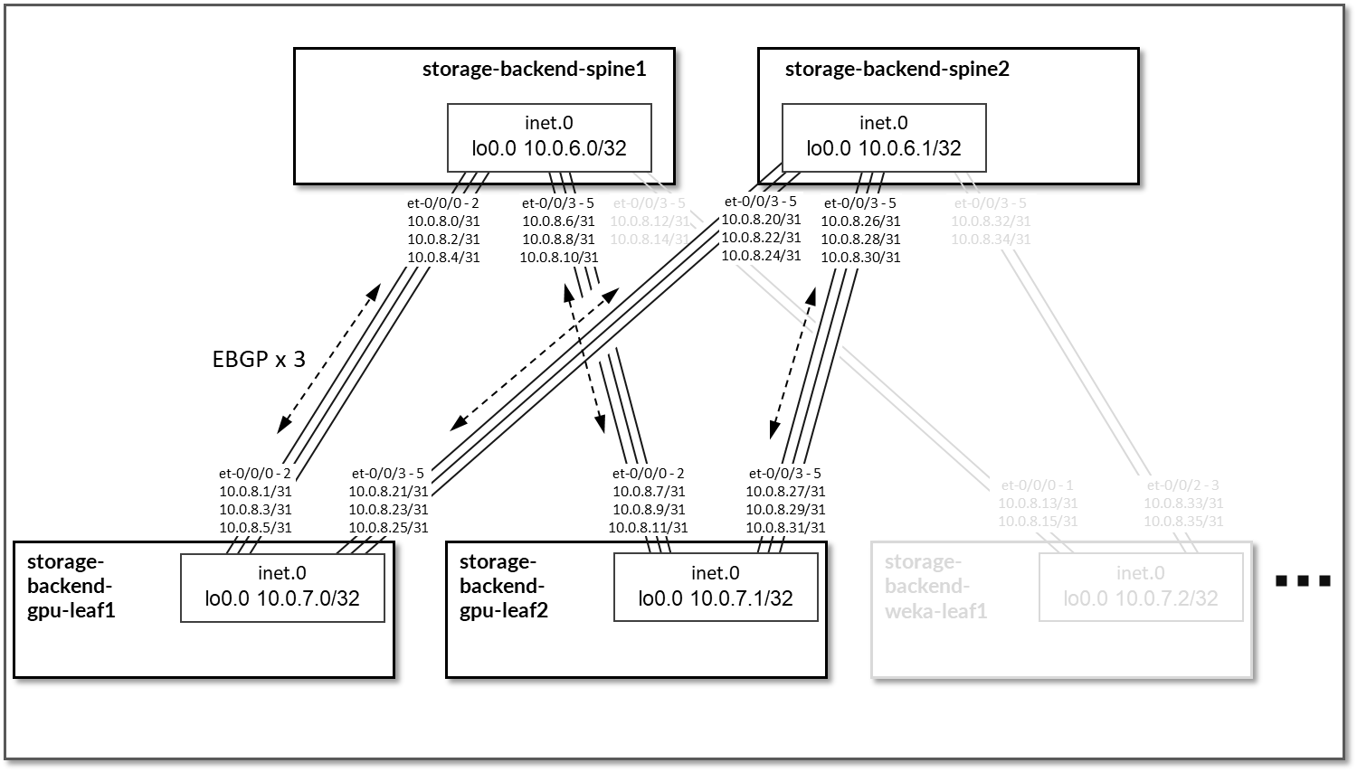
Figure 94: Storage Backend Spine to Storage Backend Leave for
WEKA Servers EBGP 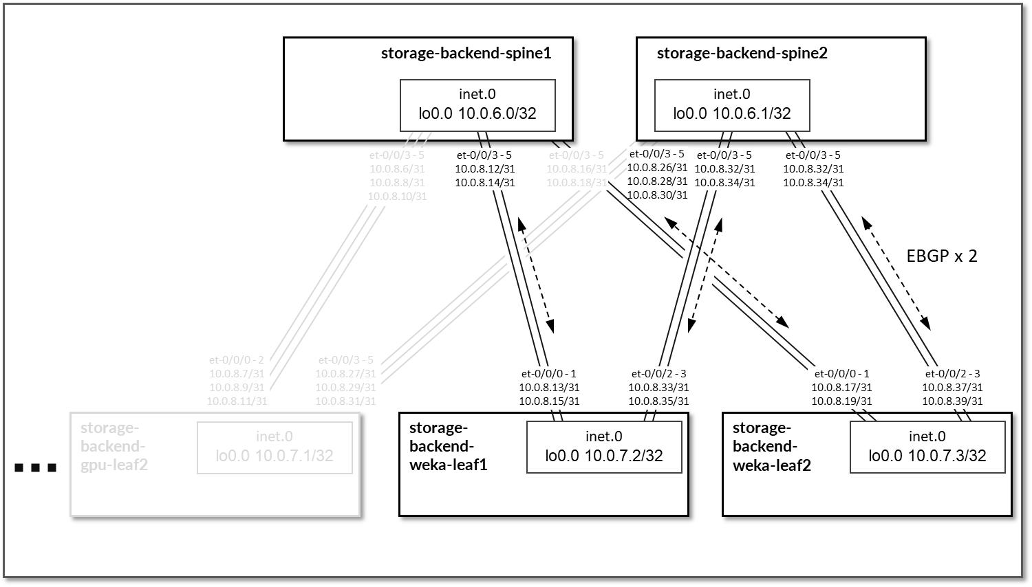
Table 46: Storage Backend Sessions
| Spine Node | Leaf Node | Spine ASN | Leaf ASN | Spine IP Address | Leaf IP Address |
|---|---|---|---|---|---|
| storage-backend-spine1 | storage-backend-gpu-leaf1 | 4201032500 | 4201032600 |
10.0.8.0/31 10.0.8.2/31 10.0.8.4/31 |
10.0.8.1/31 10.0.8.3/31 10.0.8.5/31 |
| storage-backend-spine1 | storage-backend-gpu-leaf2 | 4201032601 |
10.0.8.6/31 10.0.8.8/31 10.0.8.10/31 |
10.0.8.7/31 10.0.8.9/31 10.0.8.11/31 |
|
| storage-backend-spine1 | storage-backend-weka-leaf1 | 4201032602 |
10.0.8.12/31 10.0.8.14/31 |
10.0.8.13/31 10.0.8.15/31 |
|
| storage-backend-spine1 | storage-backend-weka-leaf2 | 4201032603 |
10.0.8.16/31 10.0.8.18/31 |
10.0.8.17/31 10.0.8.19/31 |
|
| storage-backend-spine2 | storage-backend-gpu-leaf1 | 4201032501 | 4201032600 |
10.0.8.20/31 10.0.8.22/31 10.0.8.24/31 |
10.0.8.21/31 10.0.8.23/31 10.0.8.25/31 |
| storage-backend-spine2 | storage-backend-gpu-leaf2 | 4201032601 |
10.0.8.26/31 10.0.8.28/31 10.0.8.30/31 |
10.0.8.27/31 10.0.8.29/31 10.0.8.31/31 |
|
| storage-backend-spine2 | storage-backend-weka-leaf1 | 4201032602 |
10.0.8.32/31 10.0.8.34/31 |
10.0.8.33/31 10.0.8.35/31 |
|
| storage-backend-spine2 | storage-backend-weka-leaf2 | 4201032603 |
10.0.8.36/31 10.0.8.38/31 |
10.0.8.37/31 10.0.8.39/31 |
On the Leaf nodes BGP policies are configured by Apstra to advertise the following routes to the spine nodes:
- Leaf node own loopback interface address,
- leaf to spine interfaces subnets and
- GPU/WEKA storage server to leaf node link subnets.
Figure 95: Storage Backend Leaf BGP
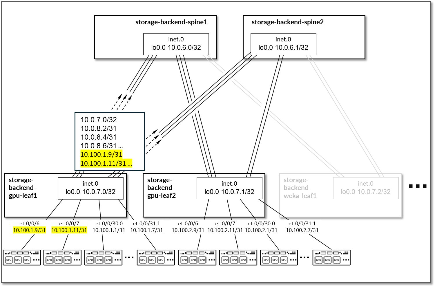
Table 47: Storage Backend Leaf Node Advertised Routes
| Leaf Node | Peer | Advertised Routes | BGP Communities | |
|---|---|---|---|---|
| storage-backend-gpu-leaf1 |
storage-backend-spine1 & storage-backend-spine2 |
10.0.7.0/32 10.0.8.0/31 10.0.8.2/31 10.0.8.4/31 10.0.8.20/31 … |
10.100.1.0/31 10.100.1.2/31 … |
3:20007 21001:26000 |
| storage-backend-gpu-leaf2 |
storage-backend-spine1 & storage-backend-spine2 |
10.0.7.1/32 10.0.8.6/31 10.0.8.8/31 10.0.8.10/31 10.0.8.26/31 … |
10.100.2.0/31 10.100.2.2/31 … |
4:20007 21001:26000 |
| storage-backend-weka-leaf1 |
storage-backend-spine1 & storage-backend-spine2 |
10.0.7.2/32 10.0.8.12/31 10.0.8.14/31 10.0.8.32/31 … |
10.100.0.16/31 10.100.0.18/31 … |
5:20007 21001:26000 |
| storage-backend-weka-leaf2 |
storage-backend-spine1 & storage-backend-spine2 |
10.0.7.3/32 10.0.8.16/31 10.0.8.17/31 10.0.8.36/31 … |
10.100.0.16/31 10.100.0.18/31 … |
6:20007 21001:26000 |
On the Spine nodes, BGP policies are configured by Apstra to advertise the following routes to the leaf nodes:
- spine node own loopback interface address
- leaf nodes’ loopback interface address
- spine to leaf interfaces subnets
- GPU/WEKA storage server to leaf node link subnets.
Figure 96: Storage Backend Spine BGP
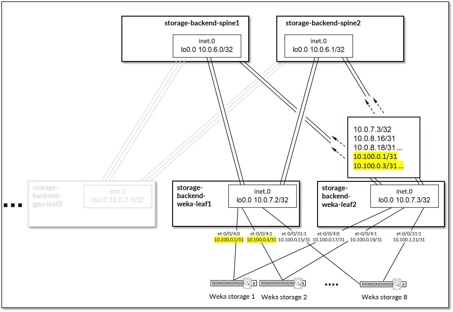
Table 48: Storage Backend Spine Node Advertised Routes
| Spine Node | Peer | Advertised Routes | BGP Communities | ||
|---|---|---|---|---|---|
| storage-backend-spine1 | storage-backend-gpu-leaf1 |
10.0.6.0/32 10.0.7.1/32 10.0.7.2/32 10.0.7.3/32 |
10.0.8.6/31 10.0.8.8/31 10.0.8.10/31 10.0.8.12/31 10.0.8.14/31 … |
10.100.0.0/31 10.100.0.2/31 … 10.100.2.0/31 10.100.2.2/31 … |
3:20007 21001:26000 |
| storage-backend-gpu-leaf2 |
10.0.6.0/32 10.0.7.0/32 10.0.7.2/32 10.0.7.3/32 |
10.0.8.0/31 10.0.8.2/31 10.0.8.4/31 10.0.8.12/31 10.0.8.14/31 … |
10.100.0.0/31 10.100.0.2/31 … 10.100.1.0/31 10.100.1.2/31 … |
||
| storage-backend-weka-leaf 1 |
10.0.6.0/32 10.0.7.0/32 10.0.7.1/32 10.0.7.3/32 |
10.0.8.0/31 10.0.8.2/31 10.0.8.4/31 … |
10.100.0.0/31 10.100.0.2/31 … 10.100.1.0/31 10.100.1.2/31 … 10.100.2.0/31 10.100.2.2/31 … |
||
| storage-backend-weka-leaf 2 |
10.0.6.0/32 10.0.7.0/32 10.0.7.1/32 10.0.7.2/32 |
10.0.8.0/31 10.0.8.2/31 10.0.8.4/31 10.0.8.20/31 … |
10.100.0.0/31 10.100.0.2/31 … 10.100.1.0/31 10.100.1.2/31 … 10.100.2.0/31 10.100.2.2/31 … |
||
| storage-backend-spine2 | storage-backend-gpu-leaf1 |
10.0.6.1/32 10.0.7.1/32 10.0.7.2/32 10.0.7.3/32 |
10.0.8.6/31 10.0.8.8/31 10.0.8.10/31 10.0.8.12/31 10.0.8.14/31 … |
10.100.0.0/31 10.100.0.2/31 … 10.100.2.0/31 10.100.2.2/31 … |
4:20007 21001:26000 |
| storage-backend-gpu-leaf2 |
10.0.6.1/32 10.0.7.0/32 10.0.7.2/32 10.0.7.3/32 |
10.0.8.0/31 10.0.8.2/31 10.0.8.4/31 10.0.8.12/31 10.0.8.14/31 … |
10.100.0.0/31 10.100.0.2/31 … 10.100.2.0/31 10.100.2.2/31 … |
||
| storage-backend-weka-leaf 1 |
10.0.6.1/32 10.0.7.0/32 10.0.7.1/32 10.0.7.3/32 |
10.0.8.0/31 10.0.8.2/31 10.0.8.4/31 … |
10.100.0.0/31 10.100.0.2/31 … 10.100.1.0/31 10.100.1.2/31 … 10.100.2.0/31 10.100.2.2/31 … |
||
| storage-backend-weka-leaf 2 |
10.0.6.0/32 10.0.7.1/32 10.0.7.2/32 10.0.7.3/32 |
10.0.8.6/31 10.0.8.8/31 10.0.8.10/31 10.0.8.12/31 10.0.8.14/31 … |
10.100.0.0/31 10.100.0.2/31 … 10.100.2.0/31 10.100.2.2/31 … |
||
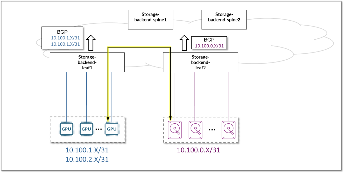
By advertising the subnet assigned to the links between the leaf nodes and the GPU/storage servers, communication between GPUs and the storage servers is possible across the fabric.
Figure 97: Storage Subnet Advertisement